ISSN:2443-1168
An Implementation of Error Minimization Data Transmission
in OFDM using Modified Convolutional Code
Hendy Briantoro, I Gede Puja Astawa, Amang Sudarsono
Politeknik Elektronika Negeri Surabaya
Jl. Raya ITS - Kampus ITS Sukolilo, Surabaya 60111, INDONESIA Telp : 62 31 594 7280, Fax : 62 31 594 6114
E-mail: [email protected], [email protected], [email protected]
Abstract
This paper presents about error minimization in OFDM system. In conventional system, usually using channel coding such as BCH Code or Convolutional Code. But, performance BCH Code or Convolutional Code is not good in implementation of OFDM System. Error bits of OFDM system without channel coding is 5.77%. Then, we used convolutional code with code rate 1/2, it can reduce error bitsonly up to 3.85%. So, we proposed OFDM system with Modified Convolutional Code. In this implementation, we used Software Define Radio (SDR), namely Universal Software Radio Peripheral (USRP) NI 2920 as the transmitter and receiver. The result of OFDM system using Modified Convolutional Code with code rate is able recover all character received so can decrease until 0% error bit. Increasing performance of Modified Convolutional Code is about 1 dB in BER of 10-4 from BCH Code and Convolutional Code. So,
performance of Modified Convolutional better than BCH Code or Convolutional Code.
Keywords: OFDM, BCH Code, Convolutional Code, Modified Convolutional Code, SDR, USRP
1. INTRODUCTION
research only used Xilinx System Generator in MATLAB with one FPGA. The data transmission was not done in the real condition from one device to another device but only in one device.
OFDMsystem has data rate faster than single carrier systems because the OFDM signal is split into multiple subcarriers. In addition, there was a researchby Ahmad Zainudin et al [3]. The reasearch was about data transmision use DPSK, DQPSK and GMSK modulation which is implemented usingUniversal Software Radio Peripheral (USRP).Unfortunately, the implementation presented and measured whether data is received succesfully or not, and was not able to recover received data [3].
In order data can be received well, it needsone or more additional techniques to increase data robustness. One of the techniques used is channel coding. There are some types of channel coding such as block code, LDPC code, BCH code and Convolutional code. A research related to channel coding has been already done by Henry Hendrix [4]. His research implemented Convolutional code and Viterbi Decode using DSK TMS320C55x Board. The drawback of the implementation is that data transmission was not done from one device to another device but only in one device. Only in one DSK TMS320C55x Board.
6, we discuss about experimental result. Finally, our conclusion is created in Section 7.
2. RELATED WORKS
In Universidade de Aveiro Portugal, there was a research by Tiago Pereiraet al [2]. It was about OFDM which implemented in FPGA. FPGA used was Virtex-6 processor. The receiver used was Maximum Likelihood (ML) and Carrier Frequency Offset (CFO) Estimator to reduce the excessive information in Cyclic Prefix (CP). The channel equalization used Zero Forcing and channel estimation used Least Square. However, the implementation of this research only used Xilinx System Generator in MATLAB with one FPGA. The data transmission was not done in the real condition from one device to another device but only in one device[2].
In addition, there was aresearch by Abirami et al[6] on analyzing the performance of OFDM using Software Define Radio (SDR) and Universal Software Radio Peripheral (USRP) in real time. Here, they use two methods, OFDM simulation in GNU Radio and OFDM in real time.The implementation of OFDM systems uses SISO(Single Input Single Output) [6]. Next, there was a researchby Ahmad Zainudin et al [3]. The reasearch was about data transmision use DPSK, DQPSK and GMSK modulation which is implemented using USRP. The implementation presented and measured whether data is received succesfully or not, and was not able to recover received data [3].
On the other hand, there was a research done by Henry Hendrix [4]. His research is about implementation Convolutional code and Viterbi Decode using DSK TMS320C55x [4]. The drawback of the implementation is that data transmission was not done from one device to another device but only in one device. Only in one DSK TMS320C55x Board.
Then, there was a research done by Irfan Y. Khan et al [7]. They improved performance of OFDM system using Convolutional Code and BCH Code. Their research using adaptive modulation and compare the performance between Convolutional Code and BCH Code. And there was a research done by Anjali Kafaltiya et al [8]. They improved performance of MIMO OFDM using combination BCH Coding and Interleaving.
3. ORIGINALITY
In this paper, we proposed channel coding Modified Convolutional code in OFDM system to achieve error minimization data transmision. Modified Convolutional Code is modification from Convolutional Code. Before data is encoded use Convolution Code, data is added with some bits which is generated by BCH Code with code rate 1/2 algorithm. This research is implemented in real condition using USRP on 910MHz carrier frequency.
4. SYSTEM DESIGN
4.1. Orthogonal Frequency Division Multiplexing (OFDM)
OFDM is a wireless technology that uses a dividing technique to divide carrier into several subcarriers which are orthogonal one another. Multiple orthogonal sub-carrier signals overlapping the spectrum can be generated by generalizing the single carrier Nyquist criterion into a multi-carrier criterion [9]. Practically, the process of the Discrete Fourier Transform (DFT) and inverse DFT (IDFT) is useful for the implementation of orthogonal signals. DFT and IDFT are efficient when the Fast Fourier Transform (FFT) and Inverse FFT (IFFT) are used. With the overlapping frequency therefore OFDM scheme can save the use of frequency. In OFDM scheme, there is a guard interval in the time domain which is called cyclic prefix (CP). This CP can reduce the inter-symbol interferences (ISI) between OFDM symbols [9]. Figure1 shows a block diagram of the transmitter and receiver in an OFDM system.
Figure 1. Block diagram of transmitter and receiver OFDM system [9]
IFFT and FFT are the main processes in OFDM system. IFFT is a modulator and FFT is the demodulator. Equation (1) and(2) show the formula of FFT and IFFT, respectively.
FFT:
(1)
IFFT :
(2)
Where x(n) is the coeffcients of the sines and cosines of frequency 2πk/N where k is the index of the frequencies over the N frequencies, and n is the time index, x(k) is the value of the spectrum for the kth frequency and x(n) is
Data transmission in OFDM system is deliveredin parallel. Then, the modulation is performed on each sub-carrier. This modulation can be BPSK, QPSK, QAM or other modulation techniques. Furthermore, the modulated signal has been applied to the Inverse Discrete Fourier Transform (IDFT) such that OFDM symbols can be generated. This allows the use of IDFT frequency allocation mutually perpendicular (orthogonal). After the OFDM symbols are converted into serial, and then the signal is sent [9].
OFDM signal x(t) in interval can be presented by
equation (3).
(3)
With x is modulate subcarrier k with frequency and is
the modulation symbol applied to subcarrier (k) during the interval to the OFDM. Modulation symbols can be BPSK, QPSK, 16QAM or 64QAM [11]. Two
orthogonal subcarriers OFDM and are presented in equation(4).
for (4)
4.3. Convolutional Code
Convolutional code is one of channel coding type. Convolutional code uses shift register and XOR gate. There are 2 parameters in convolutional code, they are rate convolutional code (R) and length of memory (K). Rate convolutional code (R) is ratio between bit input and bit output. Rate convolutional code shows in the following equation (5).
(5)
Where:
R = Rate convolutional code K = Sum of Bit input
n = Sum of Bit output
Length of memory (K) is memory with current bit input convolutional code. Length of memory can be defined with the following equation (6).
K = M +1 (6)
Where:
K = Length of Memory m = Memory
Generator polynomial is impulse respons to register memory of encoder [16]. Block diagram of Convolutional Code with rate ½ and K = 3 is
shown in figure 2 where the generator polynomial is [111 101]2, R = ½ and
Figure 2. Block diagram of Convolutional Code (rate ½, K = 3) [17]
Viterbi algorithm which implemented is algorithm Maximum Likelihood (ML) and Hard decision showed in Figure 3. Convolutional encoder will code data input, e.g input (11010100). With ½code rate the codeword is (11,01,01,00,10,00,10,11). This codeword transmit to receiver. Codeword mix with noise, the codeword received is (10,01,01,01,10,00,10,11), so it different with transmit codeword.
Figure 3. Trellis Diagram of Hard Decision Decoding [4]
The trace back process starts from the concept that each branch (branch) associated with a particular input bits in coding. For example, branching from the state S2 at t=7 to the state S0 at t=8 input bits associated with '0' on the coding [4].
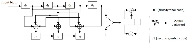
4.4. Proposed Modified Convolutional Code
As explained in Section 2, channel coding is implemented in both research [7] and [8], BCH Code and Convolutional Code are implemented alternately. The function of channel coding is to reduce error in channel so transmitted symbols is more resistant from impairment or delay in channel. Consequently, we make a new idea so that the error in channel can be solved
+
+ Input bit m
u1 (first symbol code)
better than previous by combine BCH Code and Convolutional Code and we named it is Modified Convolutional Code. We make a scenario so that signal input is encoded using Modified Convolutional Code. After that the signal is processed by modulator. Block diagram of Modified Convolutional Code is shown in figure 4.
Modified Convolutional Code is proposed channel coding which is implemented in OFDM system. Here is the algorithm of Modified Convolutional code. There are 2 big steps. First, input bit is encoded by proposed algorithm to be first codeword. Then first codeword is encoded by convolutional code algorithm to be final codeword. First codeword length is n=2m −1, for m ∈ N and distance is d ∈ N and d≤(n−1)/2. First, determine the minimum polynomial for αi, denoted mi(x), where α is a primitive root of the
unit and i=1, 2, ..., 2r. And then polynomial generator g(x),
. Form polinomial u(x) = xn−km(x) mod
g(x), where is a polynomial corresponding
to the message m=(a1,a2,...,ak), ai ∈ Z2. Thus obtained codeword c which
corresponds to a polynomial. c(x)=xn−km(x)+u(x) [10][11]. Then, first
codeword is encoded using default Convolutional Code algorithm. So, the final codeword is generated.
Figure 4. Block diagram of Modified Convolutional Code
5.System Implementation
This research implements OFDM system with channel coding Modified Convolutional Code. The system uses NI-USRP N2920 [5] from National Instrument (NI) and employs labView Software [10] to support it. The range of the frequency of NI-USRP 2920 [10] is 50 MHz up to 2,2 GHz. Universal Software Peripheral Radio (USRP) is hardware to support Software Define Radio (SDR) [12][13] in real-time condition. USRP consists of Field Programmable Gate Array (FPGA), Digital to Analog Converter (DAC) and port I/O [14].This research using NI USRP 2920 because it is affordable teaching and research solution. We can develop many algorithms but only use one device. It has bandwidth streaming at 25 MS/s for host-based processing with NI LabView [5].
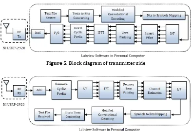
Figure 5. Block diagram of transmitter side
Figure 6. Block diagram of receiver side
On transmitter side, the first process is determining USRP’s IP address and opening the session of USRP hardware. Then, we set the IQ rate and carrier frequency. The next process is reading text file (data) and converting the string data in text file to bits of data. The size of text file is 17 Bytes which is converted into 136 bits of data. Furthermore, bits of data are encoded using Modified Convolutional Code. Encoded bits of data are mapped into symbols. Mapping symbol is determined by the type of modulation technique. There are 3 modulations used in this implementation such as BPSK, 4QAM and 16QAM. There are a bit in BPSK symbols, 2 bits in 4QAM symbol and 4 bits in16QAM symbol. And then, symbols are parallelized. After that, the pilot symbols are inserted OFDM symbols. Size of pilot symbols are 34 bits. Zero padding are added at the edges of the passband (43 zeroes as start symbol and 42 zeroes as stop symbol) and 1 zero at DC carrier. OFDM symbols are convert from frequency domain to time domain using Inverse Fast Fourier Transform (IFFT). Then, cyclic prefix are inserted to beginning OFDM symbols. Cyclic prefix from duplicating the last 64 bits of OFDM symbols. Then, OFDM symbols are converted to analog signals and transmitted using USRP.
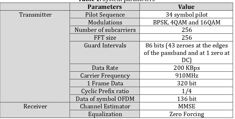
parameters are shown in Table 1.
Table 1. System parameters
Parameters Value
Transmitter Pilot Sequence 34 symbol pilot
Modulations BPSK, 4QAM and 16QAM
Number of subcarriers 256
FFT size 256
Guard Intervals 86 bits (43 zeroes at the edges of the passband and at 1 zero at
DC)
Data Rate 200 KBps
Carrier Frequency 910MHz
1 Frame Data 320 bit
Cyclic Prefix ratio 1/4
Data of symbol OFDM 136 bit
Receiver Channel Estimator MMSE
Equalization Zero Forcing
6. EXPERIMENTALRESULTS AND ANALYSIS
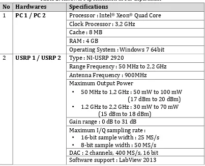
This experiment uses two Personal Computers (PCs) and two USRPs. One PC and one USRP act as transmitter, other PC and other USRP act as receiver. Figure 7 shows the topology of this experiment.Table 2 shows the hardware specification in our experiment.
Table 2. Hardware specification in our experiment
No Hardwares Specifications
1 PC 1 / PC 2 Processor : Intel® Xeon® Quad Core
Clock Processor : 3,2 GHz Cache : 8 MB
RAM : 4 GB
Operating System : Windows 7 64bit
2 USRP 1 / USRP 2 Type : NI-USRP 2920
Range Frequency : 50 MHz to 2,2 GHz Antenna Frequency : 900MHz
Maximum Output Power
• 50 MHz to 1,2 GHz : 50 mW to 100 mW
(17 dBm to 20 dBm)
• 1.2 GHz to 2,2 GHz : 30 mW to 70 mW
(15 dBm to 18 dBm) Gain range : 0 dB to 31 dB Maximum I/Q sampling rate :
• 16-bit sample width : 25 MS/s
• 8-bit sample width : 50 MS/s
DAC : 2 channels, 400 MS/s, 16 bit Software support : LabView 2013
The experiment is done in Digital Signal Processing (DSP) Laboratory PENS. Dimension of DSP Laboratory is 8 m2. Topology of DSP Laboratory’s
environment is showed in Figure 8.
There are some experiment scenarios in this research. They are measuring of error bit of OFDM system without Channel Coding, with Convolutional Code, and Modified Convolutional Code, measuringerror bit of OFDM system using Convolutional code with various number of characters, and measuringerror bit of OFDM system using Modified Convolutional code with various number of characters.
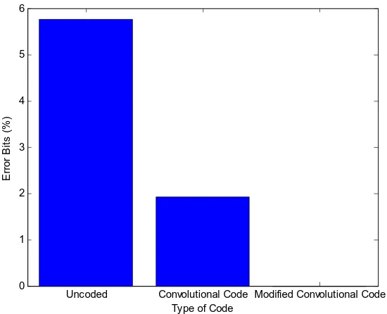
6.1 Error Bit of Data transmission without Channel Coding, with
ConvolutionalCode and Modified Convolutional Code Measurement
First experiment, transmision data use OFDM with channel coding Convolutional Code and Modified Convolutional Code. Transmited data are text file 13 bytes. Data is converted to bits data. Data is transmitted use
Figure 9.Error bits of Data Received without Code, Convolutional Code, and Modified Convolutional Code
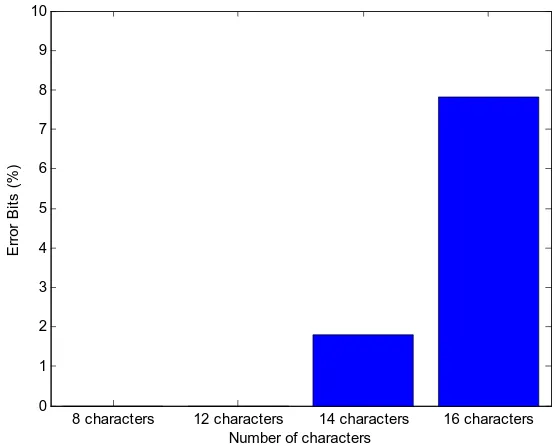
6.2 Error Bit of Data transmission using Convolutional Code with Various Number of Characters
In the second experiment, transmision data use OFDM with channel coding Convolutional Code. This experiment uses some various number of characters, they are 8 characters, 12 characters, 14 characters and 16 characters. Data is converted to bits data. Data is transmitted use 4QAM modulation. We employed Convolutional Code with code rate 3/4. The result is showed in Figure 10.
8 characters 12 characters 14 characters 16 characters
0
Figure 10. Error bits of data received using Convolutional code with various number of characters
Convolutional code with code rate 3/4is able to decode all data when using 8 and 12 characters. In 14 characters, there are 2 error bits or 1.79% of transmitted data. Then, in 16 characters there are 10 error bits or 7.81% of transmitted data, this error is large enough. For 16 characters or more, the error is more. So, Convolutional code is only able to send character under 16.
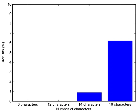
6.3 Error Bit of Data transmission using Modified Convolutional Code with Various Number of Characters
8 characters 12 characters 14 characters 16 characters
Figure 11. Error bits of data received using Modified Convolutional code with various number of characters
Modified Convolutional code with code rate 3/4 is able to decode all data when using 8 and 12 characters. In 14 characters, there are 1 error bits or 0.89% of transmitted data. Then, in 16 characters there are 8 error bits or 6.25% of transmitted data, this error is large enough. For 16 characters or more, the error is more. So, Modified Convolutional Code is only able to send character under 16.From the result of the experiment above, it can be analyzed that the Modified Convolutional Code is better than Convolutional Code.
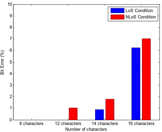
8 characters 12 characters 14 characters 16 characters
Figure 12. Error bits of data received using Modified Convolutional code in LoS condition and with obstacle condition
In LoS condition, Modified Convolutional Code is able to decode all data when using 8 and 12 characters. In 14 characters, there is a error bit or 0.89% of transmitted data. Then, in 16 characters there are 8 error bits or 6.25% of transmitted data. Meanwhile in NLoS condition, Modified Convolutional Code can decode all data when using 8 characters. In 12 characters, only there is a error bit or 1.04% of transmitted data. In 14 characters, there are 2 error bits or 1.79% of transmitted data. Then, in 16 characters there are 9 error bits or 7.03% of transmitted data. From the result of the experiment above, it can be analyzed that performance Modified Convolutional Code is enough good in NLoS condition.
6.5 Performance BER vs SNR Data Transmission using BCH Code, Convolutional Code and Modified Convolutional Code
0 1 2 3 4 5 6 7 8 9 10
Figure 13. Performance of Data Transmision using BCH Code, Convolutional Code and Modified Convolutional Code
In 0 dB, received data is corrupt. In 3dB, BCH code can decrease BER be 0.9375, Convolutional Code can decrease BER be 0.929 and Modified Convolutional Code can decrease BER be 0.946. When 7dB, Modified Convolutional Code can decrease BER be 0.011, this BER is better than BCH Code or Convolutional Code and make improvement until 0.0124. BCH Code and Convolutional Code can reduce almost all error in 9 dB but Modified Convolutional Code can reduce almost all error in 8 dB. Performance of Modified Convolutional better than BCH Code or Convolutional Code. Modified Convolutional can reduce until 0.0154 in same SNR value.
Convolutional Code can reduce almost all error in 8 dB. Performance of Modified Convolutional better than BCH Code or Convolutional Code. Modified Convolutional can reduce until 0.0154 in same SNR value. The next research will implement channel coding in MIMO OFDM system to minimize error OFDM system and use USRP.
REFERENCES
Applications, International Journal on Advances in Systems and Measurements,Vol 6 - No 1 & 2, 2013
[3] Zainuddin, Ahmad, Amang Sudarsono, I Gede Puja Astawa, Reliability
Analysis of Digital Communication for Various Data Types
Transmision Using GNU Radio and USRP, Industrial Electronic
Seminar, 2013
[4] Henry Hendrix, Viterbi Decoding Techniques for the TMS320C55x
DSP Generation, April, 2009
[5] National Instrument, An Introduction to Software Define Radio With
LabVIEW Communications System Design Software and NI USRP,
USA, 2015
[6] Abirami M, Gandhiraj R, Soman K P, Performance Analysis of Real Time OFDM Based Communication System Using GNU Radio and
USRP, International Journal of Advanced Research in Computer Science
and Software Engineering, Volume 3, Issue 6, June 2013, ISSN: 2277 128X
[7] Khan, Irfan Y., Sunil U. Nyati, and Umesh S. Bhadade, To Improve Performance of OFDM System Using Optimize Adaptive Coding
Technique with Convolutional and BCH Coding, International
Journal of Application or Innovation in Engineering & Management (IJAIEM)Vol 3 – Issue 5, 2014
[8] Kafaltiya, Anjali, and P. S. Sharma, Performance Improvement in
MIMO-OFDM using BCH Coding and Interleaving, International
Journal of Computer Applications Vol 97 – No 2, 2014.
[9] Yong Soo Cho, Jaekwon Kim, Won Young Yang, Chung-Gu Kang,
MIMO-OFDM Wireless Communications With MATLAB, Wiley, IEEE Press, 2010.
[10]Ho Shan-Yuan, Daniel J. Kleitman, An Odd Kind of BCH Code, Elsevier,
[11]Reviriegoa P., C. Argyridesb, J. A. Maestroa, Efficient error detection in
Double Error Correction BCH codes for memory applications,
Elsevier, 2012
[12]R. Gandhiraja, Ranjini Ramb, K. P. Soman, Analog and Digital
Modulation Toolkit for Software Defined Radio, Amrita Vishwa Vidyapeetham (Amrita University), India, 2012.
[13]Waqar Aziz, Ghulam Abbas, Ebtisam Ahmed, Saqib Saleem and
Qamarul-Islam, Design Analysis of Analog Data Reception Using
GNU Radio Companion (GRC), World Applied Sciences Journal 17 (1):
29-35, ISSN 1818-4952, IDOSI Publications, 2012
[14]Elizabeth A. Thompson, Natha Clem, Isaac Renninger, Timothy Loos,
Software-defined GPS receiver on USRP-platform, Purdue
![Figure 1. Block diagram of transmitter and receiver OFDM system [9]](https://thumb-ap.123doks.com/thumbv2/123dok/4040541.1983961/4.595.111.496.299.479/figure-block-diagram-transmitter-receiver-ofdm.webp)
![Figure 2. Block diagram of Convolutional Code (rate ½, K = 3) [17]](https://thumb-ap.123doks.com/thumbv2/123dok/4040541.1983961/6.595.137.483.339.562/figure-block-diagram-convolutional-code-rate-k.webp)