BACHELOR THESIS AND COLLOQUIUM
–
ME 141502
TWO STROKES DIESEL ENGINE EXHAUST VALVE
STRESS ANALYSIS USING CERAMIC (S
3N
4)
COATING
Adi Osis Nugroho
NRP 4213 101 023
Supervisor
Irfan Syarif Arief, ST., MT.
Beny Cahyono, ST., MT., Ph.D.
DEPARTMENT OF MARINE ENGINEERING
Faculty of Marine Technology
Institut Teknologi Sepuluh Nopember
Surabaya
BACHELOR THESIS – ME 141502
TWO STROKES DIESEL ENGINE EXHAUST VALVE STRESS ANALYSIS
USING CERAMIC (SI3N4) COATING
ADI OSIS NUGROHO NRP. 4213 101 023
Supervisor:
Irfan Syarif Arief, ST., MT.
Co-Supervisor:
Beny Cahyono, ST., MT., Ph.D.
DOUBLE DEGREE PROGRAM OF MARINE ENGINEERING DEPARTMENT Faculty of Marine Technology
Institut Teknologi Sepuluh Nopember Surabaya
SKRIPSI – ME 141502
ANALISA TEGANGAN KATUP GAS BUANG MESIN DISEL 2 LANGKAH MENGGUNAKAN LAPISAN
CERAMIC
(SI3N4)
ADI OSIS NUGROHO NRP. 4213 101 023
Dosen Pembibing 1: Irfan Syarif Arief, ST., MT.
Dosen Pembimbing 2: Beny Cahyono, ST. MT., Ph.D.
PROGRAM DOUBLE DEGREE
DEPARTEMEN TEKNIK SISTEM PERKAPALAN Fakultas Teknologi Kelautan
Institut Teknologi Sepuluh Nopember Surabaya
ii
iv
vi
vii
DECLARATION OF HONOUR
I hereby who signed below declare that:
This thesis has been written and developed independently without any plagiarism act. All contents and ideas drawn directly from internal and external sources are indicated such as cited sources, literatures, and other professional sources.
Name : Adi Osis Nugroho Student ID Number : 4213101023
Thesis Title : Two Strokes Diesel Engine Exhaust Valve Stress Analysis using Ceramic (Si3N4) Coating
Department : Marine Engineering
If there is plagiarism act in the future, I will be fully responsible and receive the penalty given according to the regulation applied.
Surabaya, July 2017
viii
ix
TWO STROKES DIESEL ENGINE EXHAUST VALVE STRESS ANALYSIS USING CERAMIC (SI3N4) COATING
Name : Adi Osis Nugroho NRP : 4213101023
Department : Double Degree Program of Marine Engineering Supervisor : Irfan Syarif Arief, ST., MT.
Co-Supervisor : Beny Cahyono, ST. MT., Ph.D.
ABSTRACT
Exhaust valve is an important part of a diesel engine. Exhaust valve used for control of exhaust gas and seal the combustion chamber. Failure on exhaust valve can affect the performance of the engine. On related journal, present cause of exhaust valve failure namely, fatigue, high temperature, erosion-corrosion, and wear. It found that there is a material able to withstand high temperature (10000C) without failure up to 107 cycles (more than others
common exhaust valve materials) which is ceramic (Si3N4). Ceramic can be
applied as coating on diesel engine parts (exhaust valve combustion face). Applying ceramic as coating on exhaust valve influenced the stress on exhaust valve during operation, therefore simulation test is required. FEM (Finite Element Method) is used as test tool. The simulation is divided into 3 different load cases (mechanical, thermal, and thermo-mechanical) and based on 4 models which are non-coated exhaust valve and coated with thickness variation of 0.3, 0.4, and 0.5 in mm. The result shown that exhaust valve stress increase with thermo-mechanical load at seat face area (the highest stress occur) by 1.1% (3.96 MPa) on exhaust valve with 0.5mm coating thickness compared to the non-coated exhaust valve.
x
xi
ANALISA TEGANGAN KATUP GAS BUANG MESIN DISEL 2 LANGKAH MENGGUNAKAN LAPISAN
CERAMIC
(SI
3N
4)
Nama : Adi Osis Nugroho NRP : 4213101023
Departemen : Teknik Sistem Perkapalan Program Double Degree Dosen Pembimbing : 1. Irfan Syarif Arief, ST., MT.
2. Beny Cahyono, ST. MT., Ph.D.
ABSTRAK
Katup gas buang merupakan komponen penting pada mesin disel. Katup gas buang berfungsi untuk mengatur aliran gas buang serta menjaga kekedapan pada ruang bakar. Kerusakan pada katup gas buang dapat berakibat fatal pada kinerja mesin disel. Pada penelitian sebelumnya disebutkan ada 4 penyebab terjadinya kerusakan pada katup gas buang yaitu fatigue, temperatur tinggi, erosi-korosi, dan goresan. Pada penelitian tersebut juga ditemukan ada material yang tahan terhadap suhu tinggi (10000C) sampai dengan 107 siklus (lebih tinggi dibandingkan material katup gas buang pada
umumnya) yaitu keramik (Si3N4). Keramik dapat digunakan sebagai lapisan
pada komponen mesin disel. Penggunaan lapisan keramik dapat berdampak pada tegangan yang diterima oleh katup gas buang, sehingga diperlukan pengujian untuk mengetahuinya. Pengujian dilakukan dengan metode Finite Element (FE). Pengujian terbagi menjadi 3 kasus beban (mechanical load,
thermal load, dan thermo-mechanical load) serta berdasarkan 4 model yaitu katup gas buang tanpa lapisan dan menggunakan lapisan dengan ketebalan 0.3mm, 0.4mm, dan 0.5mm. Hasil akhir menunjukkan adanya peningkatan tegangan pada beban thermo-mechanical di area seat face (lokasi tegangan terbesar) sebesar 1.1% (3.96 MPa) pada katup gas buang dengan ketebalan lapisan sebesar 0.5mm dibandingkan dengan tanpa lapisan (standar).
xii
xiii
PREFACE
Alhamdulillahirabbil ‘alamin, huge thanks to Allah SWT the God Almighty for giving intelligent, strength, health and favours so the author can finish this bachelor thesis.
This bachelor thesis aims to know stress distribution and effect of ceramic coat on exhaust valve diesel engine. The author also would express his immeasurable appreciation and deepest gratitude for those who helped in completing this Bachelor Thesis:
1. The author’s parents Bapak Suliyo and Ibu Wartini, author’s siblings, and the whole family who have always given motivation and unceasingly prayer.
2. Bapak Dr. Eng. M. Badrus Zaman, S.T., M.T. as Head Department of Marine Engineering FTK-ITS, Surabaya.
3. Bapak Irfan Syarif Arief, S.T., M.T. and Beny Cahyono S.T., M.T., Ph.D. as author supervisor in this bachelor thesis who have provided meaningful assistance, guidance, recommendation, and motivation.
4. Bapak Ir. Aguk Zuhdi M. Fathallah., M.Eng., Ph.D. as my supervisor until P1 who have provided guidance, assistance, and recommendation. 5. Bapak Ir. Dwi Priyanta, MSE as Secretary of Double Degree Marine
Engineering Program and the author academic advisor who has provided huge beneficial advisory, counsel, and motivation during college study period.
6. Author’s best friends: Alfa Muhammad Megawan, Datya Adiata
Fiantara, Dante Taufiq Akbar, and Danuja Wijayanto who have given motivation and support during completing bachelor thesis.
7. Author’s design consultant: Onggo Firstha S.T and Jangka Rulianto who have helped in design and simulation process.
8. Author’s beloved partner Arsya Sita Mianda Putri who has given motivation, suggestion, and support while author confused and remind to stay focus to finish this bachelor thesis.
The author realizes that this thesis remains far away from perfect. Therefore, every constructive suggestions and idea from all parties are highly expected by the author to improve this bachelor thesis in future. Hopefully, this bachelor thesis can be advantages for all of us, particularly for the readers.
xiv
xv
CHAPTER II LITERATURE STUDY ... 5
2.1. Diesel Engine Data and Performance ... 5
2.2. Exhaust Valve ... 7
2.2.1. Exhaust valve load ... 8
2.2.2. Exhaust valve failure ... 11
2.3. Material of Exhaust Valve ... 12
2.3.1. Nimonic 80A ... 14
2.3.2. Ceramic (Si3N4)... 15
2.4. Coating ... 17
2.5. Finite Element Analysis (FEA) ... 19
2.5.1. Von-mises stress ... 19
2.6. Safety Factor ... 20
xvi
3.1. Collecting Data ... 22
3.2. Re-design of Exhaust System ... 24
3.3. Verification ... 25
3.4. Software Simulation ... 29
3.5. Discussion ... 35
3.6. Conclusions and Recommendations ... 35
CHAPTER IV SIMULATION RESULT & DATA ANALYSIS ... 37
4.1 Simulation Result ... 37
CHAPTER V CONCLUSION AND RECOMMENDATION ... 48
5.1. Stress Distribution of Non-Coated Exhaust Valve ... 48
5.2. Stress Distribution of Nimonic 80A with Ceramic Coating ... 49
5.3. Effect of Ceramic Coating on Exhaust Valve Stress ... 50
5.4. Recommendation ... 50
REFERENCES ... 51
ATTACHMENT 1 ... 53
ATTACHMENT 2 ... 55
xvii
LIST OF FIGURES
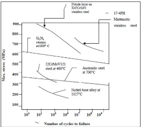
Figure 1. 1 S-N Curve for Different Materials Engine Valve at High
Temperature ... 1
Figure 1. 2 Fracture Plate of Exhaust Valve ... 2
Figure 2. 1 Power-Speed Layout Diagram ... 5
Figure 2. 2 Performance Curves ... 6
Figure 2. 3 Exhaust Valve Nomenclature ... 7
Figure 2. 4 Time Characteristic of Gas Pressure (Curve A) and the Average Gas Temperature (Curve B) for a Medium Speed 4-Stroke Engine ... 8
Figure 2. 5 Thermal Stress Distribution ... 9
Figure 2. 6 Stress Distribution Cause by Valve Spring and Cylinder Pressure ... 10
Figure 2. 7 Exhaust Valve Seat Face Failure ... 11
Figure 2. 8 Valve Stem Failure ... 12
Figure 2. 9 Damaged Piston with the Piece of Fractured Valve ... 12
Figure 2. 10 Exhaust Valve Material ... 13
Figure 2. 11 Ductile Material Stress-Strain Diagram ... 14
Figure 2. 12 Brittle Material Strain-Stress Diagram ... 15
Figure 2. 13 Energy Balance Illustration for Conventional Engine and Ceramic Coated Engine ... 17
Figure 2. 14 Von-mises Stress ... 19
Figure 3. 1 Research Flow Chart ... 21
Figure 3. 2 Exhaust Valve and Valve Seat Dimension ... 22
Figure 3. 3 Exhaust Valve 3D Form ... 24
Figure 3. 4 Cross-Section of Valve Seat 3D Form ... 25
Figure 3. 5 Fixing Supports ... 25
Figure 3. 6 Temperature Distribution ... 26
Figure 3. 7 Boundary Condition ... 27
Figure 3. 8 Thermal Stress Distribution ... 27
Figure 3. 9 Engineering Data Input... 29
Figure 3. 10 Exhaust Valve Mesh ... 30
Figure 3. 11 Exhaust Valve Load ... 32
Figure 3. 12 Thermal Stress Schematic ... 32
Figure 3. 13 Exhaust Gas Temperature Input... 33
Figure 3. 14 Valve Seat Temperature Input ... 33
Figure 3. 15 Structural Stress Schematic ... 34
Figure 3. 16 (a) Pressure Input and (b) Fixed Supports... 34
xviii
Figure 4. 1 Non-Coated (a) Temperature Distribution and (b) Thermal Stress
... 37
Figure 4. 2 Non-Coated (a) Mechanical Stress and (b) Thermo-mechanical Stress ... 37
Figure 4. 3 0.3mm Coated (a) Temperature Distribution and (b) Thermal Stress ... 38
Figure 4. 4 0.3mm Coated (a) Mechanical Stress and (b) Thermo-mechanical Stress ... 38
Figure 4. 5 0.4mm Coated (a) Temperature Distribution and (b) Thermal Stress ... 39
Figure 4. 6 0.4mm Coated (a) Mechanical Stress and (b) Thermo-mechanical Stress ... 39
Figure 4. 7 0.5mm Coated (a) temperature Distribution and (b) Thermal Stress ... 40
Figure 4. 8 0.5mm Coated (a) Mechanical Stress and (b) Thermo-mechanical Stress ... 40
Figure 4. 9 Temperature Distribution of Exhaust Valve ... 41
Figure 4. 10 Graphic of Temperature Differences at Seat Face ... 42
Figure 4. 11 Mechanical Stress Distribution of Non-Coated Exhaust Valve .. 42
Figure 4. 12 Mechanical Stress Distribution of Coated Exhaust Valve ... 43
Figure 4. 13 Thermal Stress Distribution of Non-Coated Exhaust Valve ... 43
Figure 4. 14 Thermal Stress Distribution of Coated Exhaust Valve ... 44
Figure 4. 15 Thermo-mechanical Stress Distribution of Non-Coated Exhaust Valve ... 45
Figure 4. 16 Thermo-Mechanical Stress Distribution of Coated Exhaust Valve ... 45
Figure 4. 17 Graphic of Thermo-mechanical Stress Differences ... 46
Figure 4. 18 Safety Factor Distribution of Exhaust Valve ... 46
Figure 4. 19 Safety Factor Distribution of Ceramic Coat ... 47
Figure 5. 1 Non-Coated Exhaust Valve Von-mises Stress Distribution ... 48
Figure 5. 2 Non-Coated Exhaust Valve Maximum Principal Stress Distribution ... 48
Figure 5. 3 Coated Exhaust Valve Von-mises Distribution ... 49
xix
LIST OF TABLES
Table 2. 1 Nimonic 80A Properties ... 14 Table 2. 2 Nimonic 80A Properties ... 15 Table 2. 3 Ceramtech SL 200 ST Material Properties ... 16 Table 2. 4 Silicon Nitride (Si3N4) Properties ... 16 Table 2. 5 Some Advanced Technology Ceramic Properties ... 18 Table 3. 1 Exhaust Valve Dimension ... 22 Table 3. 2 Valve Seat Dimension ... 23 Table 3. 3 Nimonic 80A Material Properties ... 23 Table 3. 4 Si3N4 Material Properties ... 23
xx
1
CHAPTER I INTRODUCTION 1.1. Background
Diesel engines use air compression to ignite the fuel produced by piston movement, because of this diesel engine works at high pressure and high temperature. Diesel engine used at ship are commonly operating for a long-term period (days), this can lead to cause engine failure because of high temperature and high pressure produced in the combustion chamber. Combustion chamber is the location of air being compressed and fuel being burned. Combustion chamber parts are consist of cylinder liner, cylinder head (exhaust valve combustion face), and piston crown.
One of all engine failure causes especially exhaust valve is due to fatigue. Fatigue in exhaust valve is because of the exhaust valve repeatedly received load (high pressure and high temperature). Repeated of high load results in materials strength failing into below the yield strength. When the material is subjected to fatigue, one or more tiny cracks usually start developing in the material, and these grow until complete failure occurs. (Raghuwanshi, Pandey, & Mandloi, 2012)
2
Previous research (Raghuwanshi, Pandey, & Mandloi, 2012) analyzes the failure of internal combustion engine valves. There are different type cause of failure namely: fatigue, high temperature (thermal stress), erosion-corrosion, and wear. Exhaust valve on those research is made of stainless steel composition (X45CrSi93). From Figure 1. 1 shows the S-N curve for different materials. The X45CrSi93 failed when 107 cycles, but there is material do not
failure up to 109 cycle operation which is ceramic Si
3N4. Si3N4 is one of ceramic
advance technology.
Figure 1. 2 Fracture Plate of Exhaust Valve (Yu & Xu, 2005)
The focus of this bachelor thesis is stress analysis on exhaust valve two strokes diesel engine. Applied stresses on exhaust valve are thermal and mechanical stress. Thermal stress comes from exhaust gas temperature. Effect of high temperature in the combustion chamber can lead damage of exhaust valve combustion face (plate), it can be seen in Figure 1. 2. To overcome those problems coating with higher strength material such as ceramic can be applied. Application of ceramic material on diesel engines can be as a coating layer on combustion chamber parts such as piston crown, cylinder liner, and exhaust valve combustion face. Effect of ceramic coating in previous research on combustion chamber parts is increasing the thermal efficiency of engines because ceramic coating reduced heat loss or heat dissipation in the combustion chamber. (Civiniz, Mustafa, Kose, Canli, & Solmaz, 2012)
The effect of Si3N4 coating on exhaust valve stress can be shown by
conduct simulation using FEM (Finite Element Method). Ceramic coating will be applied on combustion face with thickness variation. The engine that will be used on this bachelor thesis is two strokes diesel engine and the required material are nimonic 80A (base material) & ceramic Si3N4 material as a coating
3
1.2. Problems Statement
1. How the stress distribution of exhaust valve (non-coated Nimonic 80A) of a two-stroke diesel engine?
2. How the stress distribution of exhaust valve using Ceramic (Si3N4)
coating?
3. How the effect of Ceramic (Si3N4) coating on exhaust valve stress?
1.3. Research Scope
1. Exhaust valves condition for simulation: non-coating, 0.3mm ceramic coated, 0.40mm ceramic coated, and 0.50mm ceramic coated.
2. The coating is only applied on combustion face of the exhaust valve (refer to the previous journal).
3. Using two-stroke diesel engine as a sample of diesel engine. 4. Assume that the diesel engine is 100% in good condition (new
built).
5. Simulation conduct in 100% load and 100% rpm of the engine.
1.4. Research Objectives
1. To know the stress distribution on two-strokes diesel engine exhaust valve (non-coated nimonic 80A).
2. To know the stress distribution on the exhaust valve using ceramic (Si3N4) coating.
4
5
CHAPTER II LITERATURE STUDY 2.1. Diesel Engine Data and Performance
2-strokes diesel engine used as main engine for ship propulsion. The 2-strokes diesel engine has lower rpm (rotation per minute) than 4-strokes diesel engine and has bigger size than a 4-strokes diesel engine. It is commonly used for cargo ship (such as container vessel, bulk carriers, tankers, etc.) because it has a big power. This engine has a variation of power output with the number of cylinders from 5 to 12 cylinders. This two-stroke diesel engine has specification as follow:
Bore : 350 mm
Stroke : 1050 mm
Maximum exhaust gas temperature : 4200C
Maximum cylinder pressure : 140 bar
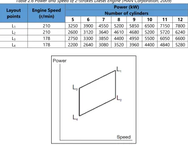
Table 2.6 Power and Speed of 2-strokes Diesel Engine (MAN Corporation, 2009)
Layout
Figure 2. 1 Power-Speed Layout Diagram (MAN Corporation, 2009)
On Figure 2. 1 shows L1 designates nominal maximum continuous
rating (nominal MCR) at 100% engine power and 100% engine speed. L2, L3,
and L4 designate layout points at the other three corners of the layout area,
6
Figure 2. 2 Performance Curves (MAN Corporation, 2009)
Performance curves indicate the output of engine with different load (power) of each cylinder. Performance curves are consist of engine speed, mean effective pressure, maximum pressure, compression pressure, scavenge air pressure, exhaust gas temperature in inlet and outlet of the turbocharger, and also Specific Fuel Oil Consumption (SFOC). From the Figure 2. 2, it can be seen that the temperature of the exhaust gas that enters the turbocharger is from 3400C up to 4200C and pressures in each cylinder is from 75 to 125 bar
7
figures are taken when the engine is operated with load variation from 50% until 100% load.
2.2. Exhaust Valve
Valves that used in internal combustion engines are: 1. Poppet valves; 2. Rotary valves; 3. Sleeve valve. The poppet valve is commonly used. The poppet valve is consist of head and stem. The seat face angle varies from 300
to 450 generally. The poppet valve derives its name from its popping
movement up and down. This is also known as mushroom valve because of its shape which is similar to a mushroom. (Sanoj & S, 2012)
Figure 2. 3 Exhaust Valve Nomenclature (Voorwald, Coisse, & Cioffi, 2011)
In 2-strokes diesel engine only has one type of valve which is exhaust valve. Exhaust valve in a 2-stroke diesel engine is located in the center of cylinder head. On the conventional type of exhaust valve, the close-open movement is controlled by cam rotation located in the camshaft. That cam will push the push rod, where the push rod will move the rocker arm and then open the exhaust valve. To close the exhaust valve, this type is used valve spring that attached in the valve stem. On this type, there is a disadvantage which is will cause wear in valve stem which leads to crack in valve stem. In order to overcome the problems associated with rocker actuation of exhaust valves, hydraulic actuation was introduced. (Anonym, n.d.)
8
exhaust valve which received the highest thermal and mechanical load since it directly contacted with the combustion chamber.
2.2.1. Exhaust valve load
The exhaust valve is main parts of exhaust gas system as controller of exhaust gas flow from the combustion process. As we already discussed before, exhaust valve works at high temperature and high pressure. Pressure and temperature of the gas in combustion chamber can reach higher than 200 bars and 16000K (See Figure 2. 4). Parts of exhaust valve which directly
contact with combustion chamber is combustion face. Therefore material that can withstand the high temperature and high pressure is needed.
Figure 2. 4 Time Characteristic of Gas Pressure (Curve A) and the Average Gas Temperature (Curve B) for a Medium Speed 4-Stroke Engine (Mollenhauer & Tschoeke, 2009) 2.2.1.1. Thermal load
In a diesel engine, the thermal load is related to temperature change due to exhaust gas that produces from combustion process. Exhaust gas flows through exhaust gas system. Exhaust gas system is started from exhaust valve that located in cylinder head which used to control exhaust gas stream into exhaust gas port (cage). However, not all exhaust valve parts are passed by exhaust gas. So, this different temperature distribution could cause thermal stress in exhaust valve, especially in valve head area because this area receives higher temperature than another area of the exhaust valve.
9
are contact with cooled parts. Seat face has lower temperature because it is contacted with the cooled valve seat.
Figure 2. 5 Thermal Stress Distribution (Witek, 2016)
Thermal stresses are stresses induced in a body as a result of a change in temperatures. The magnitude of the stress 𝜎 resulting from a temperature change from T0 to T1 is:
𝛼 : linear coefficient of thermal expansion (m/m0C)
T0 : initial temperature (0C)
T1 : initial temperature (0C)
2.2.1.2. Mechanical load (compression)
10
Figure 2. 6 Stress Distribution Cause by Valve Spring and Cylinder Pressure (Witek, 2016)
Normal stress caused by force is defined as:
𝜎 =𝐹𝐴
Compressive stress is can be calculated with formula:
𝜎 = −∆𝑙𝑙
Tensile stress is can be calculated with formula:
11
E : young modulus (N/m2) ε : strain (m/m)
2.2.2. Exhaust valve failure
Mostly failure on exhaust valves are due to exhaust valve is working at high temperature, high pressure, and tensile load from valve spring. Temperature distribution on exhaust valve in accordance with Figure 2. 5, combustion face area and lower part of valve stem has a higher temperature than another area.
Pressure from inside the cylinder produced by compression and combustion process also contribute stress on the exhaust valve, especially at valve head part. On seat face of exhaust valve will have compression stress, because that part is directly contacted with a valve seat which sustained by cylinder head (rigid body). Thermal stress (stress due to temperature change) also contribute to exhaust valve failure. Increasing of temperature caused expansion of exhaust valve which can lead to addition compression stress at seat face area. As a result of compression and thermal stress, failure can occur at seat face area as can be seen in Error! Reference source not found.9.
Figure 2. 7 Exhaust Valve Seat Face Failure (VARDAR & EKERIM, 2009)
12
On that figure, there is a fracture on valve stem (A) and fillet area of exhaust valve (B).
Figure 2. 8 Valve Stem Failure (Witek, 2016)
Failure on exhaust valve can affect the engine performance and moreover damage the engine. One of the damages caused by exhaust valve failure is on piston crown as in the figure below (Figure 2. 9). It can be seen there is damage on piston crown caused by fracture of exhaust valve fall into the combustion chamber and then stick on the piston.
Figure 2. 9 Damaged Piston with the Piece of Fractured Valve (Witek, 2016)
2.3. Material of Exhaust Valve
13
exhaust gas from combustion process normally can shoot up to 420oC and
pressure of 140 bars absolute in full load condition (MAN B&W L35MC6). Therefore, high material qualities are required to withstand high temperature and high pressure. To fulfill the requirement, exhaust valve must have specification as follows (Sanoj & S, 2012):
1. Sufficient strength and hardness to resist tensile forces and wear 2. Adequate fatigue strength
3. High creep strength 4. Resistance to corrosion
5. Resistance to oxidation at the high operating temperatures
6. Small coefficient of thermal expansion to avoid excessive thermal stresses
7. High thermal conductivity for good heat dissipation
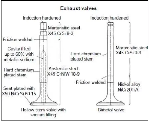
According to Figure 2. 10, there are 2 types of exhaust valve in diesel engine, namely: hollow stem and non-hollow stem. The difference is the construction which used. On this bachelor thesis, the author will use exhaust valve with non-hollow type. On this type, there are two materials which used, Martensitic steel (X45CrSi93) and Nickel alloy (NiCr20TiAl). Welding is needed to join this two material, the material will weld on each end with friction welding methods.
Figure 2. 10 Exhaust Valve Material (Mollenhauer & Tschoeke, 2009)
14
coating layer using ceramic material with grade Si3N4. Here are some
specifications of nimonic with grade 80A and also ceramic material with grade Si3N4 that obtained from several sources:
2.3.1. Nimonic 80A
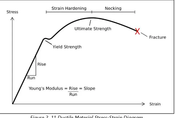
Exhaust valve material of the two-stroke diesel engine is nimonic 80A. Nimonic 80A is ductile material (Figure 2. 11). Since it is ductile material, Nimonic 80A has yield strength and tensile strength (ultimate strength). Yield strength used to calculate safety factor of ductile material. Nimonic 80A alloy is a nickel-chromium alloy that is strengthened by the additions of titanium and aluminum. It has high tensile and creep-rupture properties at temperatures up to 815oC (1500oF).
Figure 2. 11 Ductile Material Stress-Strain Diagram
The applications of nimonic 80A are gas turbine components, nuclear steam generators, die-casting inserts and cores, and also exhaust valves in internal combustion engines. The following is properties of nimonic 80A on Table 2. 1 and Table 2. 2:
A. Super Alloy Nimonic 80A (UNS N07080)
Table 2. 1 Nimonic 80A Properties (AZoM, 2013)
Properties SI SI
Physical
Density g/cm3 8.19
Melting point 0C 1320-1365
Mechanical
Tensile strength MPa 1250
Yield strength MPa 780
15
Properties SI SI
Thermal
Thermal Conductivity W/m*°K 11.2
Coefficient of Thermal Expansion 10-6m/m°C 12.7
B. Special Metals Nimonic Alloy 80A
Table 2. 2 Nimonic 80A Properties (MatWeb Material Property Data, 2017)
Properties SI SI
Physical
Density g/cm3 8.19
Mechanical
Tensile Strength, Ultimate MPa 1250
MPa 1030
Tensile Strength, Yield MPa 780
MPa 710
Elongation at break - 30%
Thermal
Thermal Conductivity W/m*°K 11.2
Coefficient of Thermal Expansion 10-6m/m°C 12.7
Melting point 0C 1320-1365
Solidius 0C 1320
Liquidius 0C 1365
2.3.2. Ceramic (Si3N4)
Figure 2. 12 Brittle Material Strain-Stress Diagram
Ceramic (Si3N4) is material that can sustain in high pressure and high pressure,
so this material is compatible if it is used as a coating on exhaust valve diesel engine. Some applications of ceramic (Si3N4) material are internal combustion
16
strength Figure 2. 12. Ultimate strength is used to calculate safety factor. Specification of ceramic (Si3N4) material from some source are as follows:
A. CeramTec SL 200 ST Silicon Nitride
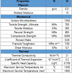
Table 2. 3 Ceramtech SL 200 ST Material Properties (MatWeb Material Property Data, 2017)
Properties SI SI
Tensile Strength, Ultimate MPa 750
Tensile Modulus GPa 305
Flexural Strength MPa 900
Compressive Strength MPa 3000
Poisson Ratio 0.26
Fracture Toughness MPa-m1/2 7.00
Shear Modulus GPa 121
Thermal
Thermal Conductivity W/m*°K 21
Coefficient of Thermal Expansion 10-6m/m°C 3.2
Specific Heat Capacity J/g0C 0.700
Maximum Service Temperature, Air 0C 1300
Maximum Service Temperature, Inert 0C 1600
B. Silicon Nitride (Si3N4) Properties
Table 2. 4 Silicon Nitride (Si3N4) Properties (AZoM, 2016)
Property Minimum Value
Compressive Strength 524 5500 MPa
Ductility 0.00031 0.00169
Elastic Limit 60 525 MPa
Endurance Limit 44 470 MPa
Fracture Toughness 1.8 6.5 MPa.m1/2
Hardness 8000 30500 MPa
Loss Coefficient 2e-005 5e-005
Modulus of Rupture 181 1050 MPa
Poisson’s Ratio 0.23 0.28
Shear Modulus 65.3 127 GPa
Tensile Strength 60 525 MPa
17
Dielectric Constant 9.5 10.5
Resistivity 1e+016 1e+021 10
-8ohm.m
2.4. Coating
Thermal barrier coating is commonly used ceramic coating on piston crown, cylinder heads and intake/exhaust valves (on combustion face). When cylinder walls are intended to be coated, a material should be selected which has proper thermal dilatation and wear resistance. Some ceramic materials have self-lubrication properties up to 870oC (Hocking, Vasatasree, & Sidky, 1989).
In Figure 2. 13, energy balance diagrams for conventional diesel engine and ceramic coated engine are given. Besides these advantages of ceramic coated low heat rejection engines, mechanical improvements also gained by lightweight ceramic materials. By their high-temperature resistance and light weight, moving parts of the engine have more duration due to low inertia and stable geometry of the parts. (Civiniz, Mustafa, Kose, Canli, & Solmaz, 2012)
Figure 2. 13 Energy Balance Illustration for Conventional Engine and Ceramic Coated Engine (Civiniz, Mustafa, Kose, Canli, & Solmaz, 2012)
18
1. Resistant to high temperatures 2. High chemical stability
3. High hardness value 4. Low densities
5. Can be found as raw material form in environment 6. Resistant to wear
7. High compression strength
There are several ceramic advanced technologies, namely: alumina
(Al-2O3), Zirconia (ZrO2), Magnesia (MgO), Berillya (BeO) and non-oxides ones.
These advanced technology ceramic properties are given in Table 2. 5.
Table 2. 5 Some Advanced Technology Ceramic Properties (Civiniz, Mustafa, Kose, Canli, & Solmaz, 2012) into two groups. Generally, up to 0.5 mm coatings named as thin coatings and thick coatings are up to 5-6 mm. Ceramic coating with thickness up to 0.5 mm are used in gas turbines, piston tops, cylinder heads and valves of otto and diesel engines. Here are several ceramic coating methods for thin and thick coating (Civiniz, Mustafa, Kose, Canli, & Solmaz, 2012):
Thermal spray coating: plasma spray, wire flame spray and powder flame spray, electrical arc spray, detonation gun technique and high-speed oxy fuel system
Chemical ceramic coating: Sole-gel, slurry, chemical vapor sedimentation, physical, vapor sedimentation, hard coating
Laser coating
Arc spark alloying
Ion enrichment method
19
coating can conduct by methods of Physical Vapor Deposition (PVD), Chemical Vapor Deposition (CVD), and Chemical Formed Processes (CFP).
2.5. Finite Element Analysis (FEA)
Testing strength of the material or applied stress can be use two methods, laboratory testing (experimental method) and numerical method (FEM). On laboratory test or experimental method, specimen material and the testing device must be prepared. Universal Testing Machine (UTM) used to test the tensile strength and compressive stress of materials. The experimental method is used to validate of FEM result.
FEM (Finite Element Method) is another technique to test materials. features of FEM are structural analysis, heat transfer, fluid flow, etc. One of the advantages of FEM is known thermal stress based on temperature distribution. On this bachelor thesis use von-mises stress to analyze the stress distribution.
2.5.1. Von-mises stress
Figure 2. 14 Von-mises Stress
Von-mises stress is used to predict yielding of materials under
σ1: maximum principal stress
20
2.6. Safety Factor
Safety factor or also known as Factor of Safety (FoS), used to provide design stress margin over material stress capacity (yield stress). There are two definitions for factor of safety:
1. The ratio of actual strength to actual applied load. Factor of safety can be calculated as:
Factor of Safety = 𝑀𝑎𝑡𝑒𝑟𝑖𝑎𝑙 𝑆𝑡𝑟𝑒𝑛𝑔𝑡ℎ
𝑊𝑜𝑟𝑘𝑖𝑛𝑔 𝑆𝑡𝑟𝑒𝑠𝑠
Equation 2. 6
Where:
Material Strength (MPa)
Working Stress (MPa)
21
CHAPTER III METHODOLOGY
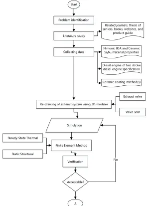
This bachelor thesis conduct with simulations of exhaust valve system of 2-strokes diesel engine with 4 variations, which are: non-coated; nimonic 80A with 0.30 mm ceramic coated; nimonic 80A with 0.40 mm ceramic coated and nimonic 80A with 0.50 mm ceramic coated. The re-design process is conducted using 3D modeler and will analyze using Finite Element Method (FEM) for the thermal and mechanical load at 100% load and 100% rpm. The methodology of this bachelor thesis can be seen in Figure 3. 1 Research Flow Chart.
Start
Problem identification
Literature study
Collecting data
Re-drawing of exhaust system using 3D modeler
Simulation Si₃N₄ material properties
Diesel engine of two stroke diesel engine specification
Ceramic coating method(s)
Finite Element Method
Verification No
22
Figure 3. 1 Research Flow Chart (Continued)
Flowchart explanation:
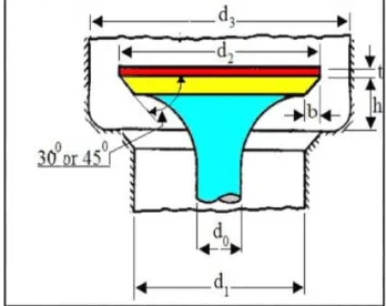
3.1. Collecting Data
There are several required data to conduct this bachelor namely: 1. Diesel engine specification such as: 1. exhaust valve size & valve seat
dimension (Figure 3. 2); 2. exhaust gas temperature & cylinder pressure at 100% load and 100% rpm obtained from project guide. The dimension of the exhaust valve and valve seat can be seen at Table 3. 1 and Table 3. 2. Exhaust gas temperature is 420oC and pressure
inside the cylinder is 140 bar obtained from diesel engine project guide (Figure 2. 2).
Figure 3. 2 Exhaust Valve and Valve Seat Dimension (Gawale & Shelke, 2016)
Table 3. 1 Exhaust Valve Dimension
Symbol Design Parameter Value
d2 combustion face diameter 181.52 mm
b width of seating 17.4 mm
d0 diameter of valve stem 40.2 mm
α Seating angle 30
l Length of valve stem 526.54 mm
23
Table 3. 2 Valve Seat Dimension
Symbol Design Parameter Value
d1 Port Diameter 152.26 mm
d3 Valve Head Opening Diameter (Calculated) 236.92 mm
h Valve Lift (Calculated) 43.95mm
2. Nimonic 80A and Ceramic (Si3N4) material properties can be seen at
Table 3. 3 and Table 3. 4. In finite element analysis for steady state thermal and static structural required some properties data of material, namely:
Density
Modulus Elasticity (Young Modulus)
Poison Ratio
Table 3. 3 Nimonic 80A Material Properties
Properties Value Unit
Density 8190 kg/m3
Coefficient of Thermal Expansion 1.27x10^-5 m/m0C
Young Modulus 2.25x10^11 Pa
Poisson's Ratio 0.3 -
Bulk Modulus 1.875x10^11 Pa
Shear Modulus 8.654x10^10 Pa
Tensile Yield Strength 7.8x10^8 Pa
Tensile Ultimate Strength 1.25x10^9 Pa
Isotropic Thermal Conductivity 11.2 W/m0C
Table 3. 4 Si3N4 Material Properties
Properties Value Unit
Density 3210 kg/m3
Coefficient of Thermal Expansion 3.2x10^-6 m/m0C
Young Modulus 3.05x10^11 Pa
Poison's Ratio 0.26 -
Bulk Modulus 2.12x10^11 Pa
24
Properties Value Unit
Tensile Ultimate Strength 7.5x10^8 Pa
Isotropic Thermal Conductivity 21 W/m0C
3. Ceramic coating (thin) layer method for the exhaust valve. Since maximum coating thickness for diesel engine components is 0.5mm, so the variation of the coating are 0.3mm, 0.4mm, and 0.5mm. Point number 1, 2, & 3 are used to determine the design parameter that will be used for stress analysis. Materials that will be used are Nimonic 80A as base material and ceramic (Si3N4) as a coating layer on combustion
face.
3.2. Re-design of Exhaust System
Re-design of the exhaust system (exhaust valve and valve seat) with 3D design modeler regarding type and size of the two diesel engine sample. In the process of modeling, the size required are exhaust valve dimension, valve seat dimension, and coating thickness. On this step, the ceramic coating is also designed at combustion face with thickness variation: 0.3mm, 0.4mm, and 0.5mm.
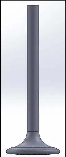
1. Exhaust Valve
According to Table 3. 1, the exhaust valve 3D form can be seen in Figure 3. 3.
25
2. Valve seat
In order to achieve of exhaust valve stress as real condition, valve seat used as fixed supports. According to Table 3. 2, the valve seat of 2-strokes diesel engine can be seen in Figure 3. 4.
Figure 3. 4 Cross-Section of Valve Seat 3D Form
3.3. Verification
After conduct simulation using FEM, there are some steps for verified the simulation results to be fulfilled, namely:
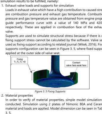
1. Exhaust valve loads and supports for simulation
Loads in exhaust valve which have a high contribution to caused stress are combustion pressure and exhaust gas temperature. Combustion pressure and gas temperature value are obtained from engine project guide performance curve with a value of 140 MPa and 420oC
respectively. These are applied in combustion face of the exhaust valve.
Supports are used to simulate structural stress because if there is no fixing support stress cannot be calculated by the software. Valve seat used as fixing support according to related journal (Witek, 2016). Fixed supports configuration can be seen in Figure 3. 5, where fixed support applied at the outer side of valve seat.
Figure 3. 5 Fixing Supports
2. Material properties
26
Table 3. 5 Simple Model Dimension
Model H
Temperatures are given at the outer side of nimonic 80A and ceramic with a value of 250oC and 420oC respectively. The result can be seen
in Figure 3. 6.
Figure 3. 6 Temperature Distribution
Temperature at ceramic outer side is 420oC
Temperature between ceramic and nimonic (T3) is 419.69oC
Temperature at nimonic outer side is 250oC
Manual calculation is conduct to ensure material properties (thermal conductivity) works. From Error! Reference source not found.10 obtained:
Rcondtotal : Total conductivity resistance (𝐿 𝑘.𝐴)
27
Qtotal : 693.15𝐾−523.15𝐾377 3360𝐾/𝑊
Static-structural conduct to simulate thermal stress caused by temperature change. Simulation is conducted with boundary condition (Figure 3. 7) of:
Fixing support at the outer side of nimonic and ceramic.
Different temperature from the initial condition is 15oC (ΔT).
Figure 3. 7 Boundary Condition
Thermal stress result can be seen in Figure 3. 8, the highest von-mises stress is 43.722 MPa and the lowest is 42.558 MPa.
28
Manual calculation is conduct to ensure mechanical properties of nimonic and ceramic are proper. To calculate thermal stress some mechanical properties are required, namely:
1. Young’s Modulus (E)
ENimonic : 2.25 x 10¹¹ Pa
ECeramic : 3.05 x 10¹¹ Pa
2. Thermal expansion coefficient (α)
αNimonic : 12.7 x 10⁻⁶/oC
3. Location of stress occurs
29
existing journal concerning on stress location are occur on exhaust valve (Kum-Chul, Sang-Woo Cha, & Ji-Ho Kim, 2014). Types of the simulation are thermal stress and structural stress. Comparison result can be seen in Table 3. 6, it can be seen the stress that caused by thermal distribution is located at seat face and stress caused by thermo-mechanical is also located on seat face area. Since results from simulation and existing journal are similar (in the location of stress are occurs), research can be continued.
Table 3. 6 Location the Stress Occur
Stress Simulation Existing Journal
Thermal load used for analyze the design and simulate the operation condition of a diesel engine (temperature and pressure). After all required data has been obtained, here are steps or stages of the simulation using FEM:
30
Figure 3. 9 Engineering Data Input
Engineering data input is the process of input the material properties of nimonic 80A and Si3N4 to the software material properties database
(Figure 3. 9). The required material properties data as follows:
Density
Modulus Elasticity (Young Modulus)
Poison Ratio
After inputting data of material properties, simulation cannot conduct before meshing process is done. Meshing process is dividing geometry of model into elements and nodes. The quantity of node or element are affected results of the simulation, more of nodes or elements/meshing will give a better result. An example of meshing result of exhaust valve can be seen in Figure 3. 10. Meshing configuration on this bachelor thesis is:
Use advance size function : Curvature
Relevance center : Fine
Initial size seed : Active Assembly
Smoothing : High
Transition : Slow
31
Figure 3. 10 Exhaust Valve Mesh
There are some indicators to indicate the mesh result is good or not, which are: aspect ratio and skewness. Aspect ratio is a comparison between the longest side and shortest side from the element. Best value of aspect ratio is an approach to 1. Skewness is the other indicators of mesh quality, quality of mesh depend on skewness value can be seen in Table 3. 7.
Table 3. 7 Skewness Value Value of Skewness Cell Quality
1 degenerate
After meshing process and optimization of mesh from the geometry then the results can be seen in Table 3. 8. Skewness factor (average) of all 4 samples are below of 0.25 which indicated the mesh is excellent.
Table 3. 8 Meshing Results
Indicator Non-Coating 0.3mm 0.4mm 0.5mm
Nodes 526230 529629 527610 526222
Elements 355929 358637 357169 355909
Skewness 0.24505 0.24785 0.24539 0.24508
32
There are 2 surface contacts on this simulation. First surface contact is defined at the adjacent surface between the valve seat and seat face. Frictional type was used with 0.05 frictional coefficient, it is based on the existing journal (Witek, 2016). The second surface contact is between ceramic (coating) and nimonic 80A (exhaust valve) material. Since ceramic material is used as a coating, bonded contact type is used. These two surface contacts are used in each simulation (load case) of each coating thickness variation.
4. Boundary Condition
The boundary condition is environment condition or it can be as load(s) and support(s) on the geometry. Loads in exhaust valve diesel engine are temperature of exhaust gas, pressure from inside the cylinder, and fixed support on valve seat (Figure 3. 11).
Figure 3. 11 Exhaust Valve Load
Loads are given in steady-state condition, where there is no change in load with respect to time. There are two analysis systems used in this simulation (steady-state thermal and static structural) and divided into 3 different load cases, namely: 1. Thermal stress; 2. Mechanical stress; 3. Thermo-mechanical stress. The configuration of analysis system for each load case are:
33
Figure 3. 12 Thermal Stress Schematic
There are 2 parts (analysis systems) on thermal stress analysis, which are steady-state thermal and static structural. Steady-state thermal is used to apply thermal loads: exhaust gas temperature and valve seat temperature. Exhaust gas temperature that applied is 420oC at combustion face, it is based on engine performance curves
data. The second load is temperature of 250oC on the valve seat.
Loads of steady state thermal is presents in Error! Reference source not found.Figure 3. 13 and Figure 3. 14.
Figure 3. 13 Exhaust Gas Temperature Input
34
Figure 3. 14 Valve Seat Temperature Input
4.2.Mechanical Stress (2nd load)
Figure 3. 15 Structural Stress Schematic
35
(a) (b)
Figure 3. 16 (a) Pressure Input and (b) Fixed Supports
4.3.Thermo-Mechanical Stress (3rd load case)
Figure 3. 17 Thermo-Mechanical Stress Schematic
Thermo-mechanical stress simulation is a combination between steady-state thermal and static structural. Similar to 1st load case, the
36
3.5. Discussion
On this stage after comparing the simulation results with the previous journal, the author will discuss the simulation results. The topics of discussion are stress (von-mises) distribution of each load case (1st, 2nd, and 3rd) and temperature distribution of those 4 models.
3.6. Conclusions and Recommendations
37
38
CHAPTER IV SIMULATION RESULT & DATA ANALYSIS
On this chapter will discuss simulation results and analyze the results. Simulation results will be divided according to coating thickness. Simulation results present of temperature distribution, thermal stress, mechanical stress and thermo-mechanical stress.
4.1 Simulation Result 4.1.1 Non-Coating
(a) (b)
Figure 4. 1 Non-Coated (a) Temperature Distribution and (b) Thermal Stress
Figure 4. 1 (a) shows temperature distribution on the non-coated exhaust valve. The highest temperature occurs at combustion face with a value of 420oC and the lowest temperature occurs at valve seat area with a value of 274.08oC.
According to Figure 4. 1 (b) the highest thermal stress occurs at valve seat area with a value of 302.78 MPa and the lowest is 5.092x10⁻¹⁰ MPa on the valve stem.
(a) (b)
Figure 4. 2 Non-Coated (a) Mechanical Stress and (b) Thermo-mechanical Stress
value of 87.074 MPa. Another stress occurs at fillet area with a range of 67.724 MPa to 77.399 MPa. Figure 4. 2 (b) shows stress caused by the combination of the mechanical and thermal load. The highest stress occurs at seat face area with a value of 360.11 MPa.
4.1.2 0.3mm Coating
(a) (b)
Figure 4. 3 0.3mm Coated (a) Temperature Distribution and (b) Thermal Stress
Figure 4. 3 (a) show temperature distribution on exhaust valve with a 0.3mm ceramic coated, it can be seen that the highest temperature occur at combustion face with a value of 420oC and lowest temperature located at seat face area with a value of 274.24oC. Meanwhile, at Nimonic 80A combustion face the temperature is 419.52oC. On Figure 4. 3 (b) show thermal stress due to exhaust
gas temperature on the exhaust valve with the highest stress located at seat face with a value of 303.34 MPa. Meanwhile, thermal stress on combustion face (ceramic coating) is 38.426 MPa.
(a) (b)
40
Figure 4. 4 (a) show von-mises stress caused by combustion pressure on exhaust valve with coating thickness of 0.3mm. The highest stress occurs at the seat face (contact area between the exhaust valve and valve seat) with a value of 87.679 MPa, meanwhile at ceramic coating is 82.051 MPa. On Figure 4. 4 (b) show thermo-mechanical stress on exhaust valve with 0.3mm ceramic coating. The highest stress occurs on seat face with a value of 353.26 MPa, meanwhile on the ceramic coating is 120.69 MPa.
4.1.3 0.4mm Coating
(a) (b)
Figure 4. 5 0.4mm Coated (a) Temperature Distribution and (b) Thermal Stress
Figure 4. 5 (a) shows temperature distribution of exhaust valve with 0.4mm ceramic coating. The highest temperature occurs at combustion face and the lowest temperature occurs at seat face area with a value of 420oC and 274.63oC respectively. Figure 4. 5 (b) show thermal stress distribution. The highest thermal stress occurs at seat face with 302.43 MPa and 37.07 MPa at combustion face (ceramic coating).
(a) (b)
41
Figure 4. 6 (a) shows the mechanical stress of exhaust valve with the 0.4mm ceramic coating. Valve seat area has higher stress than another area with a value of 82.637 MPa, meanwhile at ceramic coating is 80.153 MPa. Figure 4. 6 (b) show the thermo-mechanical stress of exhaust valve with a 0.4mm ceramic coating, the highest stress value occurs at seat face with a value of 358.43 MPa, meanwhile at combustion face (ceramic coat) is 118.58 MPa.
4.1.4 0.5mm Coating
(a) (b)
Figure 4. 7 0.5mm Coated (a) temperature Distribution and (b) Thermal Stress
Figure 4. 7 (a) shows temperature distribution of exhaust valve with coating thickness of 0.5mm. The highest temperature located at combustion face, where this area directly contacts with combustion chamber with a value of 420oC
and the lowest temperature located at seat face with a value of 275.45oC. Figure 4. 7 (b) show thermal stress caused by exhaust gas temperature, where the highest stress occurs at seat face area with 303.83 MPa, meanwhile at combustion face (ceramic coating) is 35.562 MPa.
(a) (b)
42
Figure 4. 8 (a) show mechanical stress caused by combustion pressure on the cylinder. The highest stress occurs at the seat face with a value of 84.635 MPa. On Figure 4. 8 (b) show the thermo-mechanical stress of exhaust valve with coating thickness of 0.5mm. The highest stress occurs at seat face area with a value of 364.07 MPa and 117.32 MPa at combustion face (ceramic coating).
4.2 Data Analysis
After conduct the simulation and get the results (thermal stress, mechanical stress, and thermo-mechanical stress), it will be discussed based on temperature distribution, mechanical stress, thermal stress, thermo-mechanical stress, and the safety factor of each exhaust valve.
4.2.1 Temperature Distribution
Figure 4. 9 Temperature Distribution of Exhaust Valve
Figure 4. 9 show temperature distribution on the exhaust valve. It can be seen there is temperature differences especially on valve head area. Seat face area has a lower temperature than another area, it is because seat face area contacted with cooled parts (valve seat).
Table 4. 1 Temperature Distribution at Valve Seat Area Exhaust Valve Temperature (0C)
Non-Coating 274.08
0.3mm Coating 274.24
0.4mm Coating 274.63
0.5mm Coating 275.45
43
From Figure 4. 10 show temperature differences of 4 samples, the thicker coating will have a higher temperature at seat face area. Thermal conductivity coefficient of Nimonic 80A and Si3N4 are:
Nimonic 80A : 11.2 W/m0C
Ceramic (Si3N4) : 21 W/m0C
Figure 4. 10 Graphic of Temperature Differences at Seat Face
4.2.2 Structural Stress
Figure 4. 11 Mechanical Stress Distribution of Non-Coated Exhaust Valve
Figure 4. 11 shows von-mises stress distribution of non-coated exhaust valve caused by compression from inside the cylinder. The highest stress occurs at seat face area, it because there is valve seat as a fixing supports. Another stress occurs at combustion face and fillet area. Stress on seat face can be seen in Table 4. 2. It can be seen, the effect of ceramic coating will reduce the mechanical stress on seat face area. Exhaust valve with 0.4mm coating thickness has the lowest mechanical stress with a value of 82.637 MPa.
44
Table 4. 2 Structural Stress on Si3N4 Coating Von-misses Stress (MPa)
0.3mm 82.051
0.4mm 80.153
0.5mm 78.052
Figure 4. 12 Mechanical Stress Distribution of Coated Exhaust Valve
Figure 4. 12 shows von-mises stress distribution on coated exhaust valve. Stress occurs in the same location with the non-coating exhaust valve. The highest stress due to compression load occurs at seat face area and combustion face. Tensile stress occurs at fillet area same as a non-coating exhaust valve. Stress on ceramic coating can be seen in Table 4. 3. All mechanical stress simulation results can be seen in Error! Reference source not found..
Table 4. 3 Structural Stress on Nimonic 80A (Seat Face)
Coating Von-misses Stress (MPa)
Non-Coating 87.074
0.3mm Coating 87.679
0.4mm Coating 82.637
0.5mm Coating 84.635
4.2.3 Thermal Stress
Figure 4. 13 Thermal Stress Distribution of Non-Coated Exhaust Valve
45
seat. Since outside of valve seat are given fixed supports, then valve seat only can expand to exhaust valve caused by thermal expansion. The exhaust valve is also expanded due to temperature change, resulting in compression on seat face area which caused by expansion of valve seat and exhaust valve its self. Thermal stress on exhaust valve can be seen in Table 4. 4. It can be seen that there is a addition of thermal stress due to increasing the coating thickness on combustion face.
Table 4. 4 Thermal Stress 0n Nimonic 80A (Seat Face)
Stress (Von-mises) on Nimonic 80A (MPa)
Stress Non-Coating 0.3mm Coating 0.4mm Coating 0.5mm Coating
Thermal 302.78 303.34 302.43 303.83
Figure 4. 14 Thermal Stress Distribution of Coated Exhaust Valve
Figure 4. 14 shows thermal stress distribution on exhaust valve with ceramic coated. Thermal stress distributed at valve head and the highest stress located at seat face area. The value of thermal stress at ceramic coating can be seen in Table 4. 5.
Table 4. 5 Thermal Stress on Si3n4
Stress (Von-mises) on Si3N4 (MPa)
Stress 0.3mm Coating 0.4mm Coating 0.5mm Coating
Thermal 38.426 37.07 35.562
46
4.2.4 Thermo-Mechanical Stress
Figure 4. 15 Thermo-mechanical Stress Distribution of Non-Coated Exhaust Valve
Figure 4. 15 show equivalent (von-mises) stress on non-coated exhaust valve due to thermo-mechanical load. The highest stress occurs at seat face area with a value of 360.11 MPa. All stress occurs at valve head area since there is no tensile load from valve spring. Thermo-mechanical stress on Nimonic 80A seat face results can be seen in Table 4. 6. The stress are fluctuates, but it seems stress is increased due to increasing ceramic coating thickness.
Table 4. 6 Thermo-mechanical Stress on Nimonic 80A (Seat Face)
Stress (Von-mises) on Nimonic 80A (MPa)
Stress Non-Coating 0.3mm Coating 0.4mm Coating 0.5mm Coating
Thermo-Mechanical 360.11 353.26 358.43 364.07
Figure 4. 16 Thermo-Mechanical Stress Distribution of Coated Exhaust Valve
47
Table 4. 7 Thermo-Mechanical Stress on Si3N4
Stress (Von-mises) on Si3N4 (MPa)
Stress 0.3mm Coating 0.4mm Coating 0.5mm Coating
Thermo-Mechanical 120.69 118.58 117.32
Figure 4. 17 Graphic of Thermo-mechanical Stress Differences
4.2.5 Safety Factor
According to Equation 2. 6, safety factors of exhaust valve can be calculated. Thermo-mechanical stress is used to calculate the safety factor. An example of calculation can be seen below and results can be seen in Error! Reference source not found.21.
1. FoS of Nimonic 80A: FoS = 𝑌𝑖𝑒𝑙𝑑 𝑆𝑡𝑟𝑒𝑛𝑔𝑡ℎ
𝑊𝑜𝑟𝑘𝑖𝑛𝑔 𝑆𝑡𝑟𝑒𝑠𝑠
Since yield strength of Nimonic 80A is 780 MPa, for FoS of Nimonic 80A is:
FoS = 780 MPa/360.11 MPa = 2.17
Figure 4. 18 Safety Factor Distribution of Exhaust Valve
48
highest stress occurs at that area with a value of 2.17. It is indicated exhaust valve failure can occur in that area as Figure 2. 7 showed.
2. FoS of Si3N4
FoS = 𝑈𝑙𝑡𝑖𝑚𝑎𝑡𝑒 𝑆𝑡𝑟𝑒𝑛𝑔𝑡ℎ
𝑊𝑜𝑟𝑘𝑖𝑛𝑔 𝑆𝑡𝑟𝑒𝑠𝑠
Since the ultimate strength of Si3N4 is 750 MPa, FoS of Si3N4 on
0.5mm ceramic coating is:
FoS = 750 MPa/117.32 MPa = 6.39
Figure 4. 19 Safety Factor Distribution of Ceramic Coat
Safety factor distribution of 0.5mm ceramic coat exhaust valve can be seen in Figure 4. 19. From Table 4. 8 it can be inferred that the safety factor of ceramic coat varies from 6.21 to 6.39. The lowest safety factor located at the center of combustion face where the highest stress occurs.
Table 4. 8 Safety Factor Results
Factor of Safety
Material/Coating Non-Coating 0.3mm Coating 0.4mm Coating 0.5mm Coating
Nimonic 80A 2.17 2.21 2.18 2.14
49
CHAPTER V CONCLUSION AND RECOMMENDATION
On this chapter will analyze results from the thermo-mechanical simulation. Von-mises stress used to analyze the results. The following is an analysis based on problem statement that has been discussed.
5.1. Stress Distribution of Non-Coated Exhaust Valve
Figure 5. 1 Non-Coated Exhaust Valve Von-mises Stress Distribution
Figure 5. 1 show equivalent (von-mises) stress on the non-coated exhaust valve. The highest stress occurs at seat face area with a value of 360.11 MPa and the lowest is 1.0292x10⁻⁹ MPa located at the valve stem. High stress mostly occurs
at valve head area since there is no tensile load from valve spring.
Figure 5. 2 Non-Coated Exhaust Valve Maximum Principal Stress Distribution
50
5.2. Stress Distribution of Nimonic 80A with Ceramic Coating
Figure 5. 3 Coated Exhaust Valve Von-mises Distribution
Figure 5. 3 show von-mises stress distribution on exhaust valve with 0.5mm ceramic coated. Stress distribution of exhaust valves with a ceramic coating is similar to the non-coated exhaust valve, the highest stress occurs at seat face area. Meanwhile, stress on ceramic coating is 120.69 MPa. Von-mises stress of exhaust valve with ceramic coating can be seen in Table 4. 6.
Figure 5. 4 Coated Exhaust Valve Maximum Principal Stress Distribution
51
5.3. Effect of Ceramic Coating on Exhaust Valve Stress
According to Table 4. 6 and Table 4. 7, effect ceramic coating on exhaust valve is the stress increased along with the increase of coating thickness. Exhaust valve with 0.3mm ceramic coating has the lowest stress with a value of 353.26 MPa. Meanwhile, stress on ceramic coating is decreased along with the additional thickness of the coating. But in overall, stress distribution on non-coated exhaust valve and coated exhaust valve are similar, the highest stress occurs seat face area.
5.4. Recommendation
1. Tensile load might be used to produce stress on the valve stem. 2. Boundary load variation based on engine rotation and engine power
output might be used.
3. Use testing result on UTM (Universal Testing Machine) to validate the simulation results.
52
REFERENCES
Adams, M. (2016, December 9). Accuratus Ceramic Corporation. Retrieved from Accuratus Ceramic Corporation Web site:
http://accuratus.com/silinit.html
Anonym. (n.d.). marinediesels.co.uk. Retrieved January 24, 2017, from
http://www.marinediesels.info/2_stroke_engine_parts/exhaust_valve.htm AZoM. (2013, July 25). AZO MATERIALS. Retrieved January 23, 2017, from
http://www.azom.com/article.aspx?ArticleID=9601
AZoM. (2016, December 9). AZO Materials. Retrieved from AZO Materials Web site: http://www.azom.com/properties.aspx?ArticleID=53
Civiniz, M., Mustafa, S. S., Kose, H., Canli, E., & Solmaz, O. (2012). Ceramic Coating Applications and Research Fields for Internal Combustion Engines. In P. F. Shi (Ed.), Ceramic Coatings - Applications in Engineering
(pp. 195-234). InTech.
Dynamic Ceramic Corporation. (2017). Dynamic Ceramic. Retrieved January 24, 2017, from http://www.dynacer.com/materials/coatings/
Gawale, M. G., & Shelke, S. N. (2016). Design and Optimization of IC Engine's Exhaust Valve. IOSR Journal of Mechanical and Civil Engineering (IOSR-JMCE), XIII(4), 85-93.
Hocking, M. G., Vasatasree, V., & Sidky, P. S. (1989). Metallic and Ceramic Coating. High Temperature and Application.
Kum-Chul, O., Sang-Woo Cha, & Ji-Ho Kim. (2014). A Study of Durability Analysis Methodology for Engine Valve Considering Head Thermal Deformation and Dynamic Behavior. 2014 SIMULIA Community Conference, (pp. 1-12). Rhode Island.
MAN Corporation. (2009). MAN B&W L35MC6 Project Guide (6th ed.). Denmark: MAN Diesel.
MatWeb Material Property Data. (2017). About Us: MatWeb. Retrieved March 10, 2017, from
http://www.matweb.com/search/DataSheet.aspx?MatGUID=7ffc704ef25 e4a6f8c2c262c7ff727fd
MatWeb Material Property Data. (2017). MatWeb. Retrieved March 10, 2017, from
http://matweb.com/search/DataSheet.aspx?MatGUID=c2c74a32631345f bbc4a2aa79f19f92d
Mollenhauer, K., & Tschoeke, H. (2009). Handbook of Diesel Engines. Berlin: Springer.
53
Raghuwanshi, N. K., Pandey, A., & Mandloi, R. K. (2012). Failure Analysis of Internal Combustion Engine. International Journal of Innovative Research in Science, Engineering and Technology, I(2), 173-181.
Sanoj, T., & S, B. (2012). Thermo Mechanical Analysis of Engine Valves.
International Journal of Sience and Research (IJSR), III(5), 1834-1838. VARDAR, N., & EKERIM, A. (2009). Investigation of Exhaust Valve Failure in
Heavy-duty Diesel Engine. Gazi University Journal of Science, 493-499. Voorwald, H., Coisse, R., & Cioffi, M. (2011). Fatigue Strength of X45CrSi93
Stainless Steel Applied as Internal Combustion Engine Valves. Procedia Engineering, 10, 1256-1261.
William D. Callister, J., & Retwisch, D. G. (2013). Materials Science and Engineering. USA: Wiley.
Witek, L. (2016). Failure and thermo-mechanical stress analysis of the exhaust.
Engineering Failure Analysis, 154-165.
ATTACHMENT 3– SIMULATION RESULT 4.1. Non-Coated
4.1.1. Temperature distribution
4.1.3. Mechanical stress
4.2. 0.3mm Coated
4.2.1. Temperature distribution
4.2.3. Mechanical stress
4.3. 0.4mm Coated
4.3.1. Temperature distribution
4.3.3. Mechanical stress
4.4. 0.5mm Coated
4.4.1. Temperature distribution
4.4.3. Mechanical stress
AUTHOR BIOGRAPHY
The author was born in Jakarta, 16th May 1995 as the third child from three siblings. He has taken formal education in SDN Pondok Pinang 10 Pagi, SMPN 161 Jakarta, and SMAN 29 Jakarta. After graduated from SMAN 29 Jakarta in 2013, authors proceed to pursue bachelor degree at Department of Marine Engineering (Double Degree Program), Faculty of Marine Technology-Institut Teknologi Sepuluh Nopember &Hochschule Wismar Germany specializing in Marine Manufacture and Design field. During study period, author actively participates in event held by HIMASISKAL or Marine Engineering Department such as seminars, trainings, and forums. The authors also active in sports and has winning several tournament namely: twice champion of FTK Futsal Championship in 2016 and 2017, runner-up of ITS Futsal Championship in 2017.
Adi Osis Nugroho