MEMORY EFFICIENT SEMI-GLOBAL MATCHING
Heiko Hirschm ¨uller and Maximilian Buder and Ines Ernst
Commission ICWG III/VII
KEY WORDS:Stereoscopic, Matching, Real-time, Robotics, Hardware
ABSTRACT:
Semi-Global Matching (SGM) is a robust stereo method that has proven its usefulness in various applications ranging from aerial image matching to driver assistance systems. It supports pixelwise matching for maintaining sharp object boundaries and fine structures and can be implemented efficiently on different computation hardware. Furthermore, the method is not sensitive to the choice of parameters. The structure of the matching algorithm is well suited to be processed by highly paralleling hardware e.g. FPGAs and GPUs. The drawback of SGM is the temporary memory requirement that depends on the number of pixels and the disparity range. On the one hand this results in long idle times due to the bandwidth limitations of the external memory and on the other hand the capacity bounds are quickly reached. A full HD image with a size of 1920×1080 pixels and a disparity range of 512 pixels requires already 1 billion elements, which is at least several GB of RAM, depending on the element size, wich are not available at standard FPGA- and GPU-boards. The novel memory efficient (eSGM) method is an advancement in which the amount of temporary memory only depends on the number of pixels and not on the disparity range. This permits matching of huge images in one piece and reduces the requirements of the memory bandwidth for real-time mobile robotics. The feature comes at the cost of 50% more compute operations as compared to SGM. This overhead is compensated by the previously idle compute logic within the FPGA and the GPU and therefore results in an overall performance increase. We show that eSGM produces the same high quality disparity images as SGM and demonstrate its performance both on an aerial image pair with 142 MPixel and within a real-time mobile robotic application. We have implemented the new method on the CPU, GPU and FPGA. We conclude that eSGM is advantageous for a GPU implementation and essential for an implementation on our FPGA.
1 MOTIVATION
The justification for SGM arises from the limitations of other global approaches for the real-world applications.
Graph Cuts (Kolmogorov and Zabih, 2001, Szeliski et al., 2008) is a global stereo method that translates the matching problem into a graph and seeks a partition, which effectively approxi-mates the minimization of a global energy. The method is not only slow, but also quite memory intensive. Belief Propagation (Felzenszwalb and Huttenlocher, 2004, Szeliski et al., 2008) is another approach for minimizing a global cost function. It passes messages iteratively in a three dimensional grid structure for ap-proximating the global minimum. The size of the temporary memory is linear to the number of pixels and the disparity range, as explained above. A Dynamic Programming stereo matching method (Birchfield and Tomasi, 1998) can be implemented with much less memory requirements, since the method optimizes the global function along each scanline separately. Unfortunately, this leads to streaking artifacts.
The Semi-Global Matching (SGM) method (Hirschm¨uller, 2008) minimizes a global cost function only in one dimension like Dy-namic Programming, but the direction is not oriented along scan-lines. Instead, it is performed symmetrically from eight direc-tions towards all pixels in the image. SGM does not suffer from streaking artifacts like Dynamic Programming and does not re-quire iterations like Belief Propagation. The rather simple and regular integer operations of the SGM algorithm make it suitable for implementations on the GPU (Rosenberg et al., 2006, Gibson and Marques, 2008, Ernst and Hirschm¨uller, 2008) and FPGA (Gehrig et al., 2009, Banz et al., 2010), which permits real-time performance.
In practice, SGM appears rather robust and insensitive to the choice of parameters in contrast to other methods like Graph
Cuts. This makes SGM suitable for real world applications like (tilewise) aerial image matching (Hirschm¨uller, 2008, Gehrke et al., 2010) and automotive applications (Steingrube et al., 2009).
The drawback of SGM is its memory consumption that depends, as for all global methods, on the number of pixels and the dis-parity range. This limitation may be overcome in principle with tilling the input data. While this approach is usually sufficient for CPUs it does not take advantage of the high degree of parallelism commonly found in FPGAs and GPUs.
2 MEMORY EFFICIENT SEMI-GLOBAL MATCHING
The SGM method (Hirschm¨uller, 2008) aims to minimize the global cost function
E(D) =X p
(C(p, D(p)) +
X
q∈Np
P1T[|D(p)−D(q)|= 1]
+ X
q∈Np
P2T[|D(p)−D(q)|>1]).
(1)
The function consists of one term that sums the matching costsC
over all pixelsp, according to given disparitiesDp. For rectified
images, the absolute difference would be calculated by
C(p, d) =|IL(p)−IR(p−d)|. (2)
This just serves as an example. In practice, more robust matching costs should be used (Hirschm¨uller and Scharstein, 2009). The second term of (1) sums small penaltiesP1 for all pixels, where
disparity difference to neighboring pixels. The goal is to find the disparity imageDthat minimizes this function.
2.1 Review of the SGM Method
In SGM (Hirschm¨uller, 2008), the minimization of (1) is done by going along one dimensional pathsLin eight directionsrthrough
the image. Thus, at each pixelp, paths from eight directions meet
as shown on the left in Figure 1.
x
y p
8 Paths from all Directions r
x, y d
r(p, d)
Minimum Cost Path L
p
Figure 1: Aggregation of costs in disparity space.
Along each pathLr, the minimum cost to reach all disparities of a pixelpon the path is computed according to the global cost
function (1). The minimum cost along a path is visualized on the right in Figure 1. Mathematically, the cost computation is done by recursively computing
Lr(p, d) =C(p, d) + min(Lr(p−r, d),
Lr(p−r, d−1) +P1,
Lr(p−r, d+ 1) +P1,
min
i Lr(p−r, i) +P2)−mink Lr(p−r, k).
(3)
Thus, for each pixelpand disparityd, the cost is computed by
the sum of the matching cost and the minimum path cost of the previous pixelp−r, considering the penaltiesP1andP2. The
latter is done by computing the minimum over four values. The first value is the path cost at the previous pixel at the same dis-parity. This value is taken without any penalty. The second and third value is the path cost at the previous pixel with the next lower and higher disparity. Here, the small penaltyP1is added.
The last value is the minimum cost at the previous pixel over all disparities with the additional higher penaltyP2.
The last term of equation (3) subtracts the minimum cost at the previous pixel from all costs of the current pixel. This is done for keeping the valuesLlow for using a small data type. In fact, an arbitrary value could be chosen, as long as it is constant for all disparities. The minimum of the previous pixel is used, because it is already available and subtraction will never make the whole term negative.
Since disparity changes are usually indicated by intensity changes, the penaltyP2 is adapted to the intensity gradient between the
current and the previous pixel, according to
P2=
P′
2
|IL(p)−IL(p−r)|. (4)
The information from all paths is fused for all pixels and dispari-ties by
S(p, d) =
X
r
Lr(p, d). (5)
The disparity for each pixel corresponds to the minimum cost, i.e.
DL(p) = argmin d
S(p, d). (6)
Subpixel interpolation can be performed by either fitting a parabola through the neighboring cost values or by using an equiangular line fit (Shimizu and Okutomi, 2005). The choice depends on the matching cost.
Unlike Dynamic Programming solutions, the pathwise cost com-putation does not contain any handling for occlusions. This is not possible because the paths are not oriented in the direction of epipolar lines. Therefore, the disparity of the right imageDRis
computed by either a diagonal search inS(Hirschm¨uller, 2008), or by switching the roles of the left and right image and puting from scratch. A consistency check is performed by com-paringDLwithDRand differing disparities are set to invalid or
interpolated if needed (Hirschm¨uller, 2008).
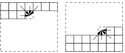
Aggregation can be performed in two passes. The first pass goes from the top left pixel line wise through the image and computes the path from left, diagonally from top-left, from top and diag-onally from top-right. For each pixel, the four paths are contin-ued from the previous pixels to the current pixel according to (3) as shown on the left in Figure 2. This requires storing the path costsLrfor the previous pixels for all disparities for each
direc-tion separately. Consequently, the required memory has a size of 3×w×dmax+dmaxelements, withwas width of the image
anddmaxas disparity range. After computing the four pathwise
costs for a pixel, the result is added according to (5) to the array
S, which has the sizew×h×dmaxelements.
Figure 2: Calculation of the eight path directions in a top-down pass (left) and a bottom-up pass (right).
Thereafter, a second pass is required that starts from the bottom, right pixel and goes upwards for computing the remaining four paths. This completes the computation ofS. The disparity image is derived fromSimmediately according to equation (6). Thus, the total temporary memory requirement of SGM is
Msgm=w×h×dmax+ 3×w×dmax+dmax. (7)
The main problem is the memory size ofSas it depends on the width, height and disparity range. In contrast, the memory for pathwise costs only depends on the width and disparity range. Since a disparity range that is larger than the total image size does not make sense, the required memory will be at most in the order of the size of the input image.
2.2 The Novel eSGM Method
minimum of the eight paths would be the same disparity. How-ever, we have to anticipate that paths from some directions may be disturbed, e.g. near depth discontinuities. Nevertheless, at least one path should predict the disparity correctly. The idea is to focus only at the locations ofS, where the eight paths have their minima. These are at most eight distinct places. For all other disparities, the costs need not to be stored. Thus,S be-comes a sparseS′
, whose size does not depend on the number of disparities any more.
Figure 3: Costs for all disparities of a certain pixel from paths of eight different directions that are summed toS. The minimum of
Smay differ from the minima of the pathwise costs.
The immediate question is if we do not reduce the number of pos-sible disparities too early? What if the minimum ofSis at a dif-ferent location than the minimum of any of the eight paths? The answer is that it is very unlikely thattruedisparity is not detected by any of the pathsandat the same time appears as minimum in
S. We claim that if the minimum ofSis at a different place than any of the eight pathwise minima, then it can only be the correct disparity by pure chance. Thus, the new eSGM method should have qualitatively the same output as the SGM method.
The new method can be implemented with three passes. The first pass works like in the original method, except for storing the re-sult toS. Instead of storing the costs for all disparities, for each pixel the four minima of the four paths that meet in this pixel are determined and the costs are only stored for these four dispari-ties. For subpixel interpolation, the costs of the next lower and higher disparity is stored as well. Figure 4 shows the values that need to be stored for one pixel. The second pass computes the remaining four paths from the bottom up. The costs are added at the places that were identified by the first pass. These four places are complete, which allows the computation of an intermediate result by choosing the lowest cost among the four and calculat-ing the sub-pixel disparity position. This frees the memory of the four minima of the first pass. The memory is used for storing the costs at the four minima of the paths from the second pass, which are in general different to the minima of the first pass. The aggre-gation is completed by a third pass that computes the same paths as in the first pass, but adds the costs at the minima that where identified in the second pass. The final minima of each pixel can then be selected among these four minima and the intermediate result of the second pass.
S(d0−1)
Figure 4: Definition of 18 data elements that need to be stored for each pixel in the eSGM method.
Thus, for this algorithm, the amount of temporary memory is just
Mesgm=w×h×18 + 3×w×dmax+dmax. (8)
Obviously, the computational effort of eSGM is increased by 50% in comparison to SGM due to the necessary third pass.
The new eSGM method does not allow the direct derivation of the right disparity image from the cost arraySby a diagonal search (Hirschm¨uller, 2008). Therefore, we suggest another kind of fast consistency check that projectsDLdirectly intoDRby
consid-ering the costs that are available at the disparities ofDL. For
rectified images it can be written asDR(x−DL(x, y), y) :=
DL(x, y). Double mappings are resolved by storing the disparity
with the lower associated cost intoDR.
The reasoning behind the new method permits the derivation of matching confidence as the number of paths that have the min-imum at the same disparity as the final disparity. Obviously, if paths from all directions have the same minimum, then the trust in the found disparity is very high. In contrast, if other path di-rections suggest a different disparity, then the confidence in the correctness of the match is lower. Computing this confidence number is computationally very cheap, because the eSGM algo-rithm already computes the individual minima of all paths.
3 IMPLEMENTATIONS
We have implemented the new method on different hardware plat-forms for different applications. As matching cost, we have fo-cused on Census, since this matching cost appears to have the highest radiometric robustness (Hirschm¨uller and Scharstein, 2009).
3.1 CPU
We have implemented the SGM and eSGM method on the CPU as explained in Section 2 using unsigned integer values with 16 bit as basic elements. The pathwise cost calculation loop is com-puted using SSE2 vector commands. In case of SGM, the Census matching cost was computed only once and the pairwise match-ing costs stored for each pixel and disparity, which doubles the memory requirement, but offers fastest processing. Thus, the to-tal temporary memory requirement in bytes of our SGM imple-mentation is four times equation (7).
Our eSGM implementation uses unsigned 16 bit integer values as well and computes the Hamming distance of Census transformed images for each of the three passes, usingxorandpopcnt com-mands, that are part of the SSE 4.2 or SSE 4a specification. Thus, the total amount temporary memory in bytes is two times equa-tion (8).
3.2 GPU
The GPU implementation of eSGM uses conventional OpenGL/Cg (Segal and Akeley, 2009, NVI, 2009) programming techniques (Rosenberg et al., 2006, Ernst and Hirschm¨uller, 2008). Several render buffers of an OpenGL frame buffer object keep the data in a 16 bit float data format while the arithmetic operations are usually done in 32 bit float precision. All the work is carried out through the execution of OpenGL rendering commands with spe-cialized fragment and vertex shaders. With respect to the mem-ory bandwidth, necessary for direct matching cost calculation, we have chosen a Census cost function with a5×5window and al-ternatively Mutual Information as matching cost (Hirschm¨uller and Scharstein, 2009). Mutual Information requires a hierarchi-cal eSGM algorithm.
first step for the second one. The memory size forS′
with eight values per pixel and the data structures for storing the minimal path cost indices and values is sufficient for computing images up to2048×2048pixels on a GPU with OpenGL/Cg. A dispar-ity range of up to 2048 pixels is only limited by the 16 bit float data format of the buffers. For consistency checking on the GPU, the right disparity image is calculated from scratch with swapped input images. Alternatively the fast consistency check method of Section 2.2 can be used.
3.3 FPGA
Programmable hardware like FPGAs have been used for stereo methods like SGM (Banz et al., 2010, Gehrig et al., 2009). FP-GAs have a low power consumption and high computational power that make them suitable for energy aware embedded systems that demand real-time image processing. A FPGA implementation of the original SGM algorithm on a high-end FPGA board matches two pairs of 320x200 images at 27 frames/s using ZSAD as match-ing cost (Gehrig et al., 2009). Durmatch-ing our FPGA implementation efforts it became clear that the required memory bandwidth is the limiting factor for increased image resolutions or deploying low cost FPGAs in mass production.
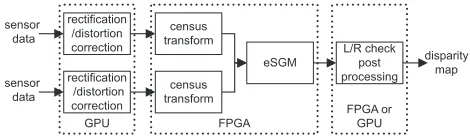
FPGA or
Figure 5: Overview of the functional blocks and the underlying heterogeneous hardware platform.
Unlike other FPGA implementations (Gehrig et al., 2009) we are using Census as matching cost, as it is well suited for hardware realization and because of superior performance under realistic conditions (Hirschm¨uller and Scharstein, 2009, Hirschm¨uller and Gehrig, 2009). The window size of the Census transform can be set to any arbitrary size. For our real-time setup, the census size was chosen to be5×5, since we found that it gives the best trade-off between hardware impact and image quality.
All hardware components are designed with the hardware de-scription language VHDL, following a hardware operating sys-tem concept (HW-OS). The HW-OS allows for a fast interchange of already deployed and proven hardware modules, at the expense of 5-10 % additional resource utilization. The eSGM core is cus-tomizable to any disparity and image resolution, which must be a power of two. Our hardware platform consists of a mid-sized Xilinx Virtex 5 FPGA (XC5VSX95T) with a PCI express in-terface to the image sensors and a GPU. The GPU is used for pre- and post-processing as shown in Figure 5. Based on this hardware environment, a stereo image pair with a resolution of 1024×1024pixels and a maximum of 64 disparity steps can be processed at nearly 10 Hz. VGA sized image pairs are processed at 33 Hz with the same disparity range. The consistency check doubles the execution time. A second independent matching core may be instantiated in a FPGA with more logic resources. The novel eSGM method has also proven its feasibility on low cost Xilinx Spartan Devices.
4 RESULTS
We have tested our implementations of SGM and eSGM against each other on a standard test set, on huge images and on different platforms for finding out the advantageous and disadvantageous of our new method.
4.1 Evaluation on Middlebury Datasets
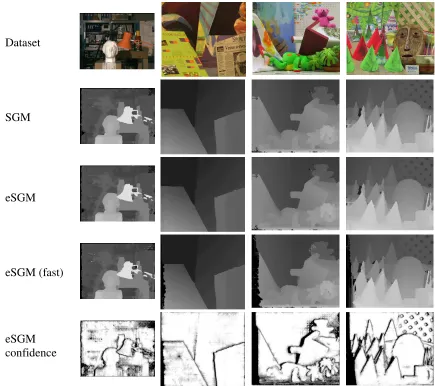
Figure 6 shows the standard data sets from the Middlebury web page (Scharstein and Szeliski, 2010, Scharstein and Szeliski, 2002, Scharstein and Szeliski, 2003). We used the same parameter set-tings for SGM and eSGM and for all images. The consistency check was used for identifying occlusions, which were interpo-lated as explained in Section 2.1.
The disparity images of SGM and eSGM are almost identical. In contrast, eSGM with the fast consistency check produces worse results. The last row of Figure 6 shows the confidence images that were computed by eSGM as explained in the end of Section 2.2. Obviously, lower confidence is estimated near object bor-ders, which is in fact the place where most errors occur.
All pixels that differ by more than one pixel from the ground truth are counted as error. Table 1 shows the results over all non-occluded pixels. The performance of SGM and eSGM is very similar, which confirms that the eSGM method produces virtually the same output as the SGM method. The original SGM imple-mentation is listed as SemiGlob in the table. The difference to our implementation is the matching cost. We have used Census. In contrast SemiGlob uses Mutual Information, which is slightly inferior (Hirschm¨uller and Scharstein, 2009).
The runtime is given in the last column of Table 1. We have measured it on a Xeon X5570 CPU with 3 GHz. The implemen-tation is single threaded, thus only one CPU core was used. In this example, eSGM is 56% slower than SGM, which confirms the theoretical runtime overhead of 50%.
4.2 Matching of Huge Images
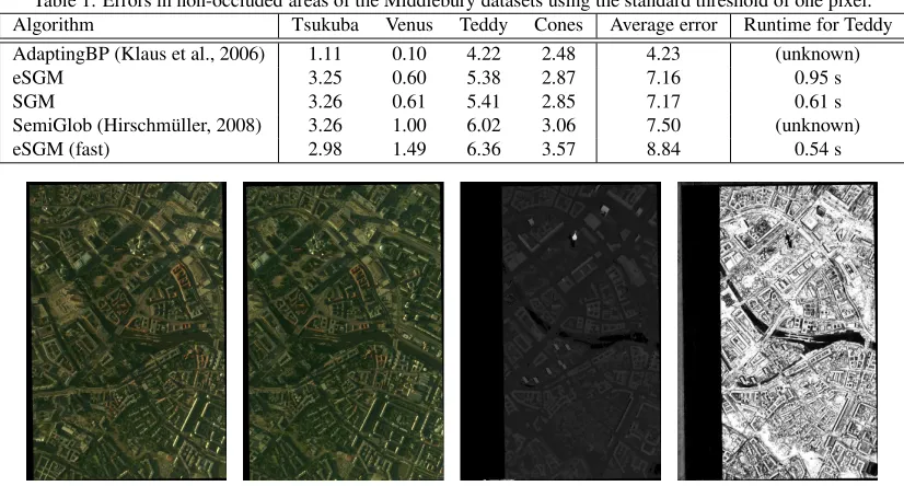
The main advantage of SGM is the possibility to match huge images in one piece without tiling. Figure 7 shows a rectified aerial image pair. Both images have a size of9782×14580 = 142MPixel. The disparity range in this example is 1788 to 2300, thus 512 pixels, mainly due to the tower, which has a height of ≈370m in reality.
eSGM computed the disparity and confidence image, as shown in Figure 7, in one piece using 4.8 GB of temporary memory. It re-quired 72 Minutes on a Xeon X5570 CPU with 3 GHz in a single threaded implementation. The SGM implementation would re-quire 272 GB of memory for computing the whole image, which is absolutely unrealistic. Instead the disparity image is computed in7×11tiles of the size1478×1406pixels and required 4 GB of temporary memory. Thus, the tiles have an overlap of 40 pixels. The computation time was 51 Minutes. The resulting disparity image looks the same as the eSGM result and is therefore omit-ted. The problem of tiling is the definition of the overlap. For well textured, rather flat scenes, as the current one, a low overlap of 20-40 pixels is sufficient. However, low-textured scenes, water or high depth differences require a higher overlap. With eSGM, this problem is avoided.
eSGM
confidence
eSGM (fast)
eSGM
SGM
Dataset
Figure 6: Comparison of our SGM and eSGM implementation on the Middlebury datasets.
4.3 Computation Time on Different Hardware
As discussed before, we have implemented the new method on three different hardware platforms. All implementations use Cen-sus as matching cost and a full consistency check. The CPU ver-sion runs single threaded on one CPU core. Parallelization into several threads appears feasible, but is not used. Table 2 shows the runtime using two different image configurations.
Table 2: Runtime in seconds of SGM and eSGM on one CPU core (Xeon X5570, 3 GHz), GPU (NVidia GeForce G280) and FPGA (Xilinx Virtex 5, 125 MHz).
Method (Hardware) 640×480×64 2k×2k×1k
SGM (CPU) 1.11 s 150.9 s
SGM (GPU) 0.13 s
-eSGM (CPU) 2.14 s 250.9 s
eSGM (GPU) 0.24 s 26.5 s
eSGM (FPGA) 0.06 s
-These results show that eSGM has special advantageous on the GPU and the FPGA, because these platforms typically have not as much memory available as the CPU implementation and the ra-tio between computara-tion power and memory bandwidth is worse. On the GPU, especially the memory size is a problem. An image of size2048×2048pixels and 1024 pixel disparity range cannot be computed by SGM, but by eSGM. On the FPGA, the mem-ory size as well as the memmem-ory bandwidth is a problem, which is
relaxed by the eSGM method.
5 CONCLUSION
We have shown that the novel eSGM method improves the SGM algorithm by making its temporary memory requirement inde-pendent from the disparity range without sacrificing matching quality. The novel feature comes at the cost of around 50% more computation time as compared to SGM.
We have argued that memory efficiency is very important for ap-plying global stereo methods to real world problems. As the im-age resolution increases in future, the disparity range increases as well. This means that the problem will become worse in future, if the main memory does not increase over-proportional to the image resolution.
The novel eSGM method permits matching of huge images up to several hundred MPixel in one piece on the CPU, which is not possibly by any other similarly accurate stereo method. The benefit of eSGM is even higher on the GPU and the FPGA as the main memory size is more limited on these devices and the ratio between computational power to memory bandwidth is worse.
REFERENCES
match-Table 1: Errors in non-occluded areas of the Middlebury datasets using the standard threshold of one pixel. Algorithm Tsukuba Venus Teddy Cones Average error Runtime for Teddy AdaptingBP (Klaus et al., 2006) 1.11 0.10 4.22 2.48 4.23 (unknown)
eSGM 3.25 0.60 5.38 2.87 7.16 0.95 s
SGM 3.26 0.61 5.41 2.85 7.17 0.61 s
SemiGlob (Hirschm¨uller, 2008) 3.26 1.00 6.02 3.06 7.50 (unknown)
eSGM (fast) 2.98 1.49 6.36 3.57 8.84 0.54 s
Figure 7: Left and right rectified aerial image with 142 MPixel, disparity image by eSGM and corresponding confidence image.
ing disparity estimation: Architecture and fpga-implementation. In: IEEE Conference on Embedded Computer Systems: Archi-tectures, Modeling and Simulation.
Birchfield, S. and Tomasi, C., 1998. Depth discontinuities by pixel-to-pixel stereo. In: ICCV, Mumbai, India, pp. 1073–1080. Ernst, I. and Hirschm¨uller, H., 2008. Mutual information based semi-global stereo matching on the gpu. In: ISVC, Vol. LNCS 5358, Part 1, Las Vegas, NV, USA, pp. 228–239.
Felzenszwalb, P. F. and Huttenlocher, D. P., 2004. Efficient belief propagation for early vision. In: IEEE CVPR.
Gehrig, S., Eberli, F. and Meyer, T., 2009. A real-time low-power stereo vision engine using semi-global matching. In: ICVS, Vol. LNCS 5815, Liege, Belgium, pp. 134–143.
Gehrke, S., Morin, K., Downey, M., Boehrer, N. and Fuchs, T., 2010. Semi-global matching: An alternative to lidar for dsm gen-eration? In: Canadian Geomatics Conference and Symposium of Commission I, ISPRS, Calgary, Canada.
Gibson, J. and Marques, O., 2008. Stereo depth with a unified architecture gpu. In: IEEE CVPR.
Hirschm¨uller, H., 2008. Stereo processing by semi-global match-ing and mutual information. IEEE TPAMI 30(2), pp. 328–341.
Hirschm¨uller, H. and Gehrig, S., 2009. Stereo matching in the presence of sub-pixel calibration errors. In: IEEE CVPR, Miami, FL, USA, pp. 437–444.
Hirschm¨uller, H. and Scharstein, D., 2009. Evaluation of stereo matching costs on images with radiometric differences. IEEE TPAMI 31(9), pp. 1582–1599.
Klaus, A., Sormann, M. and Karner, K., 2006. Segment-based stereo matching using belief propagation and a self-adapting dis-similarity measure. In: ICPR.
Kolmogorov, V. and Zabih, R., 2001. Computing visual corre-spondence with occlusions using graph cuts. In: ICCV, Vol. 2, pp. 508–515.
NVI, 2009. CG Reference Manual. 2.2 edn.
Rosenberg, I. D., Davidson, P. L., Muller, C. M. R. and Han, J. Y., 2006. Real-time stereo vision using semi-global matching on programmable graphics hardware. In: SIGGRAPH.
Scharstein, D. and Szeliski, R., 2002. A taxonomy and evalua-tion of dense two-frame stereo correspondence algorithms. IJCV 47(1/2/3), pp. 7–42.
Scharstein, D. and Szeliski, R., 2003. High-accuracy stereo depth maps using structured light. In: IEEE CVPR, Vol. 1, Madison, Winsconsin, USA, pp. 195–202.
Scharstein, D. and Szeliski, R., 2010. Middlebury stereo website. www.middlebury.edu/stereo.
Segal, M. and Akeley, K., 2009. The OpenGL Graphics System: A Specification.
Shimizu, M. and Okutomi, M., 2005. Sub-pixel estimation error cancellation on area-based matching. IJCV 63(6), pp. 207–224.
Steingrube, P., Gehrig, S. and Franke, U., 2009. Performance evaluation of stereo algorithms for automotive applications. In: ICVS, Vol. LNCS 5815, Liege, Belgium.