Tilt and Heading Measurement Using Sensor Fusion
Abstract— Inertial measurement units (IMUs) typically contain three orthogonal rate-gyroscopes and three orthogonal accelerometers, measuring angular velocity and linear acceleration respectively. In this research, we try to make sensor fusion from IMU sensors to measure tilt and heading value. We use IMU that has 3 sensors with 3-axis each, accelerometer, gyroscope plus magnetometer. The design puts gyroscope as primary source of orientation information. Then magnetometer is used to detect yaw error and accelerometer is used to detect pitch and roll for drift correction. So that, with the accelerometer and magnetometer help for error correcting, this sensor fusion algorithm offers more stable output for tilt and heading measurement.
Index Terms— Direct Cosine Matrix, IMU, Tilt and Heading, Yaw-Pich-Roll Measurement.
of the gravity vector, and the gyros sense only the angular velocity of Earth rotation [5]. While magnetometers measure the strength and direction of the local magnetic field, allowing the north direction to be found [3]. From this three sensors different way of measure tilt, we try to make sensor fusion from this three sensors to get a better measurement with correcting error from a sensor with another sensor’s tilt measurement.
The remainder of this paper describes in detail how we measure tilt and heading from IMU. Section II presents the design of system, hardware design, program design, sensor fusion work and getting tilt and heading value. Section III presents the implementation and result of this system. The last section presents the conclusions.
II. SYSTEM DESIGN
I. INTRODUCTION
The accurate measurement of orientation plays a critical role in a range of fields including: aerospace, robotics, navigation, and human motion analysis and machine interaction [1]. For example, in an autonomous vehicle, by operating autonomously, outside control is removed from the control loop and the autonomous vehicle monitors and processes its own boards sensors to determine the which command is being accomplished [2]. For stability, an autonomous vehicle should know it’s tilt and heading condition to keep stabil. Tilt and heading measurement can be implemented using an inertial measurement unit (IMU), it is becuse an IMU typically contain three orthogonal rate-gyroscopes and three orthogonal accelerometers, measuring angular velocity and linear
A. Hardware Design
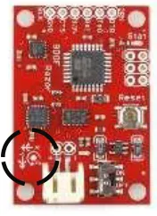
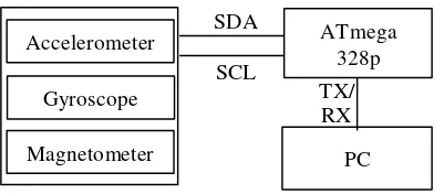
In this research, we use an IMU module from sparkfun, 9 dof razor imu. This module contains 3 axis accelerometers (ADXL345), 3 axis gyroscopeses (ITG-3200), and 3 axis magnetometers (HMC5883L). This IMU fit with our concepts that using accelerometer, gyroscope and magnetometer fot tilt and heading measurement.
This three sensors connected to a microcontroller atmega328 over one I2C pin. This module also provides a pin serial communication, we use this pin to send the tilt and heading value to another microprosessor or microcontroller even PC for another impelementation.
acceleration respectively [3]. But for autonomous missions it may be important to retain good navigation [4], and if a little error found, the autonomous missions can not be accomplish. Tilt and heading is one of navigation part, so it is very important to measure tilt and heading without error.
In this paper, we will be discussing about getting tilt and
sensors have each different way to measure tilt and heading. For a stationary IMU, the accelerometers sense only the components
B. Program Design
There are three main parts of this system programming. The first part is reading sensor, the second part is sensor fusion, and the last part is tilt and heading measurement.
IMU Sensor Reading
Sensor Fusion Algorithm
D. Sensor Fusion Algorithm
After getting all the output sensor in 3 axis, in this block, the system will fusion the output from the three sensors using Direction Cosine Matrix algorithm. This algotirhm will represent the sensor value to a 3x3 matrix, with the coloumns
In this block, the system will read the sensor’s output from all the three sensors. But, before reading the sensors, we must initialization every sensor, because every sensor have selectable user feature. We need this initialization to configure the sensor like what we need.
In order to create a coherent value, sampling time must always be the same [6], so the output data rate of each sensor must set to same, in this paper we use 50Hz data rate continuosly. Reading and initialitaztion sensor is made over i2c communication. Accelerometer’s initialization, at power register set to measurement mode, then at format data register set the output resolution to a ± 2g range with full resolution (10 Bits). At bandwidth rate register set to 50Hz data rate. Magnetometer’s initialization, at mode register set to continuous mode, and at register A set data rate’s output to 50Hz. Gyroscope’s initialization, at power management register set to default, at DLPF_FS register set to full scale with filter 42Hz, at sample rate divider register set to 50Hz sample rate, then at power management register set back to normal.
After initialization, the sensors are available to read. Accelerometer are device than can sense gravitation, in essence accelerometer measures force not acceleration. It just happens that acceleration causes an inertial force that is captured by the force detection mechanism of the accelerometer, so from the accelerometer reading we can get gravitation force in 3 axis.
Magnetometer are device that are really similar to angle around axis Y (that would be Axz angle) at time t0, and we define it as Axz0, next we measured this angle at a later time t1 and it was Axz1. The rate of change will be calculated as
Figure 3. Direction Cosine Matrix Block Diagram (Developed from [7] )
This algorithm use gyroscope as primary source of orientation change information. Then magnetometer is used to detect yaw error and accelerometer is used to detect pitch and roll for drift correction.
This algorithm must not execute every looping, it must be execute after every sensor was read (after 20ms), because this algorithm will update the DCM matrix, if this algorithm execute before sensor reading and the last sensor error correction reading is not zero, it will make the output to unstable again. We can conclude this from how the DCM works [7]:
1. The gyros are used as the primary source of orientation information. We integrate the nonlinear differential kinematic equation that relates the time rate of change in the orientation of the aircraft to its rotation rate, and its present orientation. This is done at a high rate, (40 to 50 Hz) often enough to give the servos fresh information for each and every PWM pulse that is sent to the servos.
2. Recognizing that numerical errors in the integration will gradually violate the orthogonality constraints that the DCM must satisfy, we make regular, small adjustments to the elements of the matrix to satisfy the constraints. 3. Recognizing that numerical errors, gyro drift, and gyro
Force right and Z axis pointing down.
From graphic of accelerometer output when static on Earth, we can see that x and y axis values is zero, but z-axis is not. It is because the z-axis is pointing to the Earth’s center that has a gravitation force. It means the value of accelerometer in z-axis represent 1g. Where, the output from sensor fusion algorithm block, the DCM matrix can convert to Euler angles, the pitch (θ), roll (ϕ), and yaw (ψ). If we have the full direction cosine matrix, we can convert to Euler angles from the last row and the first column of the matrix [9]:
𝜃 = −arcsin(𝑟��) (2)
𝜙 = 𝑎𝑡𝑎𝑛2(𝑟��, 𝑟��) (3)
𝜓 = 𝑎𝑡𝑎𝑛2(𝑟��, 𝑟��) (4)
III. IMPLEMENTATION AND EXPERIMENT ANALYSIS In this section, the system will be experimented. First, we will analysis the sensor reading output. Then, the experimental is to compare the tilt and heading output before using sensor fusion (only gyroscope) algorithm with the one that using sensor fusion algorithm. Then, comparing the tilt and heading measurement’s outputs from the system in this paper with actual value.
A. Sensor reading
Figure 6. Gyroscope output when static
Differ with accelerometer, even in static condition the output of gyroscope is not zero, it still measure a constant angle acceleration.
Figure 7. Accelerometer output when given outside force in x-axis
Then, from static condition, we moved the module nose up and down in x-axis. The capture of output from sensor reading shown in figure 7 and 8.
When we give a change condition in x-axis, the output of the sensor also change. When the module move nose up, the accelerometer output rises gradually, then if the module move nose down, the output decrease gradually and turn into minus. Just like accelerometer, the gyroscope output also have a positif output when we move it nose up and have a negative value when we move it nose down. But differ with accelerometer, when we stop moving the module, the value doesn’t keep stable but it keep decrease because it measure a deaclerration.
B. Sensor fussion effect
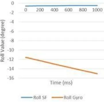
The effect of sensor fussion in tilt and heading measurement is shown in these three graphic below. Without sensor fusion algorithm, the output keep increasing overtime, this is cause of the value is not zero while in stationary condition. But after sensor fusion algorithm implemented, the system’s output still stable as the time elapsed.
Figure 9. Comparison yaw angle measurement between using sensor fusion and without sensor fusion in stationary condition
Figure 10. Comparison roll angle measurement between using sensor fusion and without sensor fusion in stationary condition
Figure 11. Comparison pitch angle measurement between using sensor fusion and without sensor fusion in stationary condition
Then, this system will be experimental to compare the value of tilt and heading measurement from the system with actual value.
Table 1. Comparison of actual measurement with system measurement with sensor fusion implemented
S t e p
Actual Measurement Output System
Yaw Pitch Roll Yaw Pitch Roll
1 90 45 90 90.04 -
90.07
45.13 - 45.19
90.08 – 90.13
2 0 0 0 0.09 -
0.14
0.11 - 0.13
0.1 – 0.5
3 -90 -45 -90 -89.92 -
-89.94
-44.07 - -44.09
-89.90 - -89.96
4 0 0 0 0.09 –
0.14
0.11 s/d 0.13
0.1 – 0.5
Table 2. Comparison of actual measurement with system measurement before sensor fusion implemented
S t e p
Actual Measurement Output System
Yaw Pitch Roll Yaw Pitch Roll
1 0 0 0 0.02 0.21 -0.06
2 90 45 -90 90.48 45.42 -93.05
3 0 0 0 1.15 -0.41 -6.08
IV. CONCLUSION
The more reference we have, the more accurate data will we
[3] W. O. J., "An introduction to inertial navigation," University of Cambridge Computer Laboratory, get. Just like the system in this paper, a gyroscope alone, it has Cambridge, 2007.
an error measurement and it growth as the time elapsed. [4] Ø. Hegrenæs, K. Gade†, O. K. Hagen† and P. E. Hagen, Accelerometers are used for roll-pitch drift correction because "Underwater Transponder Positioning and Navigation of they have zero drift in this axis [7], as well the gyroscope have Autonomous Underwater Vehicles," in MTS/IEEE
drift error. And magnetometer are used for yaw correction, OCEANS CONFERENCE AND EXHIBITION, Norway,
because it always pointing the Earth’s north. 2009.
With the accelerometer and magnetometer help for error
correcting from gyroscope error, this sensor fusion algorithm [5] Y. Zhao, GPS/IMU Integrated System for Land Vehicle Navigation based on MEMS, Sweden: Royal Institute of offers more stable output for tilt and heading measurement. Technology (KTH) Division of Geodesy and
Geoinformatics, 2011.
ACKNOWLEDGMENT [6] Camacho, K. Seifert and Oscar, "Implementing
This research supported by Telkom University and Ministry of research and technology and higher education. We would also like to thank to EIRRG laboratory for giving us a workplace.
REFERENCES
[1] S. O. Madgwick, A. J. Harrison and R. Vaidyanathan, "Estimation of IMU and MARG orientation using a
gradient descent algorithm," IEEE International
Conference on Rehabilitation Robotics, 2011.
[2] Kapaldo and A. J, Gyrosc op e Calibration and Dead R eckoning for an Autonomous Underwater Vehicle,
Blacksburg, Virginia, 2005.
Positioning Algorithms Using Accelerometers," Freescale Semiconductor, 2007.
[7] A. U. Darajat, M. Komarudin and S. R. S, "SISTEM TELEMETRI Unmanned Aerial Vehicle (UAV) BERBASIS Inertial Measurement Unit (IMU),"
ELECTRICIAN Jurnal Rekayasa dan Teknologi Elektro,
2012.
[8] W. Premerlani and P. Bizard, "Direction Cosine Matrix IMU: Theory," 2009.
![Figure 3. Direction Cosine Matrix Block Diagram (Developed from [7] )](https://thumb-ap.123doks.com/thumbv2/123dok/4029993.1973413/2.596.80.241.112.188/figure-direction-cosine-matrix-block-diagram-developed.webp)