Seminar II - AMReG 08, 15 Disember 2008, Bangi, Malaysia
1
Machining Simulation of AISI 1045 and Carbide Tool Using FEM
Hendri. Y., Jaharah A.G., Che Hassan C.H.
Department of Mechanics and MaterialsFaculty of Engineering Universiti Kebangsaan Malaysia
ABSTRACT
In recent years, the applications of finite element method (FEM) in metal cutting operations have proved to be effective in studying the cutting process and chip formation. In particular, the simulation results can be used for both researchers and machine tool makers to optimize the cutting process and designing new tools. Many researches were done on two-dimensional simulation of cutting process because the three-dimensional versions of FEM software required more computational time. The present work aims to simulate three-dimensional orthogonal cutting operations using FEM software of Deform-3D. Orthogonal cutting finite element model simulations were conducted to study the effect of cutting speed on effective-stress, strain and temperature in turning process. AISI 1045 was used as work material and cutting tool was TNMA 332 (uncoated carbide tool, SCEA = 0; BR = -5; SR = -5 and radius angle 60o). The emphasis on the designed geometries are limited to the changes in the cutting speed between 100 m/min and 450 m/min. The machining parameters of feed rate and depth of cut were kept constant at 0.35 mm/rev and 0.3 mm respectively.
The simulation results show that by increasing the cutting speed causes a decrease in cutting force and effective-strain. On the other hand, increasing in cutting speed will increase effective -strain and temperature of the chip formed.
Key Words: finite element method, three-dimensional of orthogonal cutting, AISI 1045, carbide tool
INTRODUCTION
2
machining simulation (Columbus, 2007). Applications of FEM models for machining can be divided into six groups: 1) tool edge design, 2) tool wear, 3) tool coating, 4) chip flow, 5) burr formation and 6) residual stress and surface integrity. The direct experimental approach to study machining processes is expensive and time consuming. For solving this problem, the finite element methods are most frequently used. Modeling tool wear using FEM has advantages over conventional statistical approach because it requires less experimental effort and it provides useful information such as deformations, stresses, strain and temperature in chip and the work piece, as well as the cutting force, tool stress and temperature on the tool working under specific cutting parameter. (Mackerle, 1999)
METHODOLOGY
This paper presents the application of Deform-3D in simulation orthogonal cutting process of AISI 1045 and carbide tool at various cutting speeds while the other machining parameters of feed rate and depth of cut were kept constant. The commercial software Deform-3D for deformation analysis was used to simulate orthogonal metal cutting process. It is based on an updated Lagrangian formulation and employs an implicit integration scheme. Figure 1 shows Geometry and Schematic of orthogonal cutting condition model.
Figure 2 Geometry and Schematic of orthogonal cutting condition model
defined to be a rigid body which considers thermal transfer for modeling the cutting temperature field.
Deform software had been used to simulate the effect of cutting speed on the parameter of machining when turning AISI 1045 using uncoated carbide cutting tool. The simulations were performed by changing the cutting speed while the feet rate and depth of cut were kept constant at 0.35 mm/rev and 0.3 mm respectively as shown in Table 2. The simulation results of cutting force, effective-stress, strain and chip temperature on the cutting were studied and analyzed. The operation is simulated using a nose angle 60o and without used of coolant.
The three-dimensional finite element model was generated under a plane strain assumption because the width of cut was larger than the undeformed chip thickness in this orthogonal cutting arrangement. The flow stress behavior of the work material and the contact conditions, physical and thermomechanical properties of the workpiece and tool materials, and cutting conditions are predefined and input to the simulation model as listed in Table 3.
Table 1 Flow stress models for AISI-1045 carbon steel
Material Model
Equation for flow stress σ models Material
constants
TABLE 2 Input Parameters in the simulation process
Parameters Cutting Speed (m/min)
100 150 200 250 300 350 400 450
Feed Rate Kept constant at 0.35 mm/rev
Depth of cut Kept constant at 0.3 mm
4
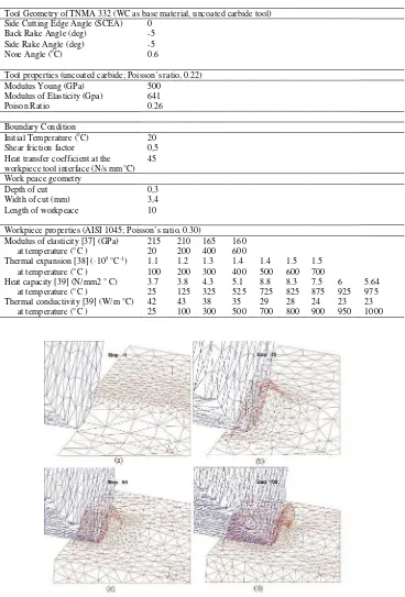
Table 3 Cutting condition to the simulation models
Tool Geometry of TNMA 332 (WC as base material, uncoated carbide tool) Side Cutting Edge Angle (SCEA) 0
Tool properties (uncoated carbide; Poisson’s ratio, 0.22) Modulus Young (GPa) 500
Modulus of Elasticity (Gpa) 641
Poison Ratio 0.26
Boundary Condition Initial Temperature (oC)
Shear friction factor Heat transfer coefficient at the workpiece tool interface (N/s mm°C)
Workpiece properties (AISI 1045; Poisson’s ratio, 0.30)
Modulus of elasticity [37] (GPa) 215 210 165 160
(c) Chip formation at step 50, (d) Developed continues chip at step 100.
Figure 3 Example of the simulation result for cutting speed at 200 m/min (for running in 300 step)
Displacement, shape and surface mesh of tool and workpiece at initial mesh in the beginning of the cutting operation until the developed chip formation at step 100 as illustrated in Figure 2 a , 2b, 2c and 2d respectively The workpiece and the tool are characteristized by non uniform mesh distribution in the simulation. Very small element is required in the contact area between tool and workpiece because of very large temperature gradient and stress that will develop in this region during the simulation. Figure 3 shows an example of simulation result for cutting speed 100 m/min that was found from 300 steps of simulation running and needs longer time simulation.
RESULT AND DISCUSSION
Detailed Study of FEM Simulation
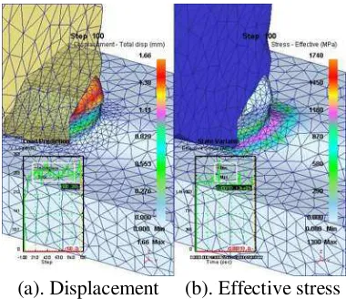
Figure 4a shows the simulation result for displacement. The longer the chip generated caused higher mesh displacement found as at the end of chip formed. The biggest deformation was occurred on the primary deformation zone, followed by the secondary deformation zone. This also cause higher stress occurred in this section. This result is agreeable with Kalhori (2001) where the major deformation during cutting process were concentrated in two region close to the cutting tool edge, and the bigger deformation were occurred in the primary deformation zone, followed by secondary deformation zone, sliding region and sticking region as shown in Figure 4b.
6
(a). Displacement (b). Effective stress
Figure 4 The simulation result for (a) displacement, cutting speed, (b). Stress and strain at 100 m/min (step 100)
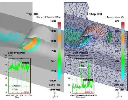
Stress and temperature can be analyzed in detail based on its contour, this will give the value of stress and temperature for each of lines or points in all region of workpiece and chip formed as shown in Figure 5 and Figure 6.
Figure 5 shows that on the primary deformation zone, higher deformation is experienced, which resulted in higher stress It can be seen the contour of stress where higher at line of H (1520 MPa) and G (1300 MPa).
Figure 5 The simulation result for stress contour at 100 m/min (Step 100)
Figure 6 The simulation result for temperature contour at 100 m/min (Step 100)
In the sticking region, the work piece material adheres to the tool and shear occurs within the chip, the frictional force is high and consequently is generated. Therefore, the highest temperature in the chip usually occurs in the sliding region. Figure 6 shows contour of temperature generated in each region, and higher temperatures are around at line of G (439oC) and H (509oC) on sliding region.
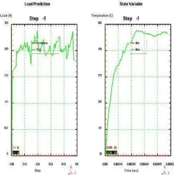
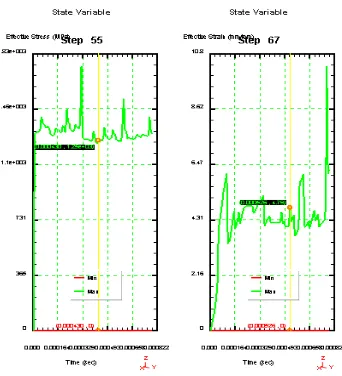
Figure 7 shows the cutting force that generated during the cutting simulation, the cutting force remained constant (fluctuation on horizontal direction) after step 20, the same phenomenon is also observed in the gradient temperature, it remained constant after Step 42. Bigger fluctuation are found in effective-strain, therefore more difficult to predict the strain value compared to predict the effective-stress as given in Figure 8.
8
Figure 8 The graph result of simulation for cutting effective-stress and strain for cutting speed 100 m/min (step 100)
Effect of Increasing of Cutting Speed on Machining Result
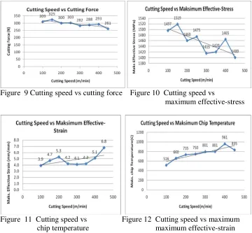
The cutting force, effective stress, strains and chip temperature at various cutting speed were studied and analyzed as shown in Table 4. The maximum and minimum value of each cutting parameter for cutting force, effective-stress, effective-strain and generated chip temperature in this simulation were plotted in Figure 9, Figure 10, Figure 11 and Figure 12 respectively.
In Table 4, the simulation for cutting speed were done for 100 m/s - 450 m/min.
Figure 9 Cutting speed vs cutting force Figure 10 Cutting speed vs
maximum effective-stress
Figure 11 Cutting speed vs Figure 12 Cutting speed vs maximum chip temperature maximum effective-strain
Figure 9 shows that by the increasing of the cutting speed, it will decrease the cutting force. This is agreeable with theory that by the increasing of cutting speed will soften the material, therefore this will make material easier to cut in higher cutting speed condition.
Figure 10 shows that by increasing the cutting speed also will reduce the effective-stress. This is also agreeable with theory and Cerenitty. Et all (1996) an other research. The good result were get for the graph of temperature where the increasing of cutting speed will increase the generated temperature on chip as given in Figure 12. This is agree with Cerenitti. et all (1996) where the maximum temperature of chip are increasing with increasing cutting speed.
10
CONCLUSION
The distribution of cutting force, effective stress and temperature obtained from simulations are in good agreement with the result given in literature.
From simulation, there can be concluded that by increasing of the cutting speed in turning of AISI 1045 using Tungsten Carbide (CW) will decreasing of cutting force and effective stress. In the different case, increasing of cutting speed cause increasing of generated temperature on chip.
ACKNOWLEDGEMENT
The authors would like to Government of Malaysia and Universiti Kebangsaan Malaysia for their financial support under 03-01-01-SF1214 and UKM-GUP-BTT-07-25-025 Grants.
REFERENCE
Aurich. J.C (2006), Finite Element Modelling of Segmented Chip Formation, Annals of the CIRP, Volume 11, 2006
Cerenitti A.E, Fallbohmer B.P, W. Wu C.W.T, Altan B.T (1996), Application of 2D FEM to Chip Formation in Orthogonal Cutting, Journal of materials Processing Technology, Elsevier Science, Volume 59
Columbus, OH (2007), DeformTM - 3D Machining (Turning) Lab, Scientific Forming Technologies Corporation.
Cerenitti.A.E,, Lazzaroni.C, Menegardo. L, Altan. T (2000), Turning
SimulationUsing a Three- Dimensional FEM Code, Journal of materials Processing Technology, Elsevier Science, Volume 98, 2000
Jawahir. I. S (2008), An Intermediatary Level Short Course on Machining
Process Modelling and Optimization for Improved Productivity, Machining Research Laboratory Center for Manufacturing, and department of
Mechanical Engineering Lexington, USA
Kalhori. V. 2001, Modelling and Simulation of Mechanical Cutting, Doctoral Thesis, Institutionen for Maskinteknik
Mackerle. J (1999), Finite Element Analysis and Simulation of Machining: a Bibliography (1976 – 1996), Journal of Materials Processing Technology, Elsevier Science, Volume 86
Marusich, T.D. and Ortiz, (1995)., Modeling and Simulation of High-Speed Machining, International Journal Num. Metallurgy Engineering, Volume 38.
Shet, C. (2000), Finite Element Analysis of the Orthogonal Metal Cutting Process, Journal of Materials Processing Technology, Elsevier Science, Volume 105
12
Email kepada
[email protected]
BORANG PENDAFTARAN
Nama :
Tajuk :
Penyelia :
No Telefon : (Pejabat)
(H/P)
E-Mail :
Hendri Yanda
Modelling of Cutting and Machining:
Turning of Ductile Cast Iron using a three-
Dimensional FEM Method
Prof. Dr. Jaharah. A. Ghani
0162365017
6/10/2017 :: Hak Cipta - AMReG
Prosiding Seminar II Kumpulan Penyelidikan Pembuatan Termaju 2008 (Seminar II - AMReG 08)
17 - 18 Disember 2008, Port Dickson, Negeri Sembilan Malaysia
ISBN 978-983-43995-2-8
Hakcipta Advanced Manufacturing Research Group (AMReG), Universiti Kebangsaan Malaysia
Hakcipta terpelihara. Tiada bahagian daripada terbitan ini boleh diterbitkan semula, disimpan untuk pengeluaran atau ditukarkan ke dalam sebarang bentuk atau dengan sebarang alat jua pun, samaada dengan cara elektronik, gambar serta rakaman dan sebagainya tanpa kebenaran bertulis dari AMReG, Universiti Kebangsaan Malaysia terlebih dahulu.
Jabatan Kejuruteraan Mekanik dan Bahan
Adobe, the Adobe logo, and Reader are either registered trademarks or trademarks of Adobe Systems Incorporated in the United States and/or other countries.
Adobe Reader download