1033 Advances in Materials and Processing Technologies II
Application of FEM in Investigating Machining Performance
Hendri Yanda
1, a, Jaharah A. Ghani
2, b, Che Hassan Che Haron
3, c 1,2,3Department of Mechanical and Materials Engineering,
Faculty of Engineering and Built Environment, Universiti Kebangsaan Malaysia,
Bangi, Selangor Darul Ehsan, 43600 Malaysia a
[email protected], b [email protected], c [email protected]
Keywords: Finite element method, machining performance, rake angle, clearance angle.
Abstract. The two biggest problems that often experienced in machining cast iron are poor machinability and high hardness. Up to now, many researchers have investigated machining performance and how to find optimum condition in machining ductile cast iron. This study aims to investigate the machining performance of ductile cast iron and carbide cutting tool using FEM. Performances were evaluated by changing the cutting tool geometries on the machining responses of cutting force, stress, strain, and generated temperature on the workpiece. Deform-3D commercial finite element software was used in this study. Ductile cast iron FCD 500 grade was used as the work piece material and carbide insert DNMA432 type with WC (Tungsten) was used for the cutting tool. The effects of rake and clearance angles were investigated by designing various tool geometries. Various combination of carbide insert geometries were designed using Solid Work to produce +15, +20 and +30 deg for rake angle and 5, 7, 8 and 9 deg for clearance angle. Machining condition for the simulations were remained constant at cutting speed of 200 m/min, feed rate of 0.35 mm/rev, and depth of cut of 0.3 mm. The results of effective-stress, strain and generated temperature on both chip and material surface were analysed. The results show that by increasing the rake angle (α), it will improves the machining performance by reducing the cutting force, stress, strain and generated temperature on surface of workpiece. But, by increasing the clearance angle (γ), it will not affect much to the cutting force, stress, strain and generated temperature on chip.
Introduction
Finite Element Analysis (FEA) technique was the first introduced in 1960s and still widely used for analysis such as in tools design and forming processes. Based on the success of FEM simulations for bulk forming processes, many researchers developed their own FEM codes to analyze metal cutting processes during the early 1980s up to now [1], [2], [3], [4] and [5]. Cerenitti et al. [1] assumed a rigid sharp tool and elasto-plastic workpiece, and defined a node separation criterion based on the geometry of the element approaching the cutting edge. Cerenitti et al. [1] used an early version of a commercial implicit FEM code “DEFORM-2DTM”. This code uses four-node quadrilateral elements and is based on static Lagrangian formulation. Today, DEFORM-3D™ code is commonly used by researchers and industry in machining simulation [6].
1034 Advances in Materials and Processing Technologies II
Methodology
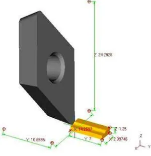
Orthogonal Cutting Condition Model. One of the important parameters in the orthogonal metal cutting process is the rake angle between the face of the cutting tool and the plane perpendicular to the cutting direction. The magnitudes of tool cutting geometries have significant effects on the performance of the cutting tool and the integrity of the cut surface. The main objective of this research is to apply the finite element method to study the rake angle and clearance effects in orthogonal metal cutting of ductile cast iron with continuous chip formation, while the other machining parameters of cutting speed, feed rate and depth of cut were kept constant. Finite element simulation results of the orthogonal metal cutting using three sets of perfectly sharp cutting tools with positive rake angles of 15, 20 and 30° and four clearance angles of 5, 7, 8 and 9 respectively. The commercial software Deform-3D for deformation analysis was used to simulate orthogonal metal cutting process. It is based on an updated Lagrangian formulation and employs an implicit integration scheme. Fig. 1 shows the schematic of orthogonal cutting condition model.
Parameter Inputs and Cutting Conditions. The three-dimensional finite element model was generated under a plane strain assumption because the width of cut was larger than the undeformed chip thickness in this orthogonal cutting arrangement. The flow stress behavior of the work material and the contact conditions were used as equation for flow stress σ models, σ = σ1εn [8]. Cutting
conditions are predefined are shown in Table 1.
Table. 1: Parameter inputs in the simulation process Parameters
Cutting speed constant at 200 m/min
Feed rate constant at 0.35 mm/rev
Depth of cut (DOC) constant at 0.3 mm
Rake angle (α), deg 15 20 30
clearance angle (β), deg 5 7 8 9 5 7 8 9 5 7 8 9
The workpiece material was ductile cast iron FCD500 grade. This material was selected as the workpiece material in this study because it was widely used in automotive application. Deform-3D software was used to simulate the effect of tool cutting geometries in turning ductile cast iron using uncoated carbide cutting tool. The simulations were performed by changing the rake angle and clearance angle while the cutting speed, feed rate and depth of cut were kept constant at 200 m/min, 0.35 mm/rev and 0.3 mm respectively. The simulation results of cutting force, effective-stress, strain and generated temperature on the workpiece surface were studied and analyzed. The operation is simulated using insert carbide of DNMA432 type that has a nose angle of 55 deg and without the use of coolant. The tool was defined to be a rigid body which considers thermal transfer
1035 Advances in Materials and Processing Technologies II
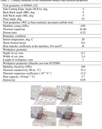
for modeling the cutting temperature field. Cutting condition, simulation models and material properties of carbide cutting tool and workpiece are shown in Table 2.
Table 2: Cutting condition to the simulation models and material properties
Displacement, shape and surface mesh of the tool and workpiece at the initial mesh of beginning the cutting operation was developed until chip formation reach step 100 as illustrated in Fig. 2a , 2b, 2c and 2d respectively. The workpiece and the tool are characteristized by non uniform mesh distribution in the simulation. Very small element is required in the contact area between tool and workpiece because of very large temperature gradient and stress that will develop in this region during the simulation.
Design of Cutting Tool Geometries. Cutting tools were designed for various rake angles of +15, +20 and +30 deg and the clearance angles of 5, 7, 8 and 9 deg. There are twelve combinations of geometry designs for carbide tool using Solid Work software as shown in Fig 3.
Tool geometry of DNMA 432
Side Cutting Edge Angle (SCEA), deg -3
Back Rack angle (BR), deg -5
Side Rack angle (SR), deg -5
Nose angle, deg 55
Tool properties (WC as base material, uncoated carbide tool)
Modulus young (GPa) 650
Thermal expansion 5e-06
Poison ratio 0.25
Boundary condition
Initial temperature, deg. C 20
Shear friction factor 0.6
Heat transfer coefficient at the interface, N/s mmoC 45 Workpiece geometry
Depth of cut, mm 0.3
Width of cut, mm 3.4
Length of workpiece, mm 7
Workpiece properties (Ductile cast iron FCD500)
Modulus elasticity (GPa) 169
Thermal conductivity (W/m. °C) 35.2
Thermal expansion coefficient (·10-6 °C-1) 12.5
Heat capacity (N/mm2 ° C) 3.7
Emissivity 0.95
1036 Advances in Materials and Processing Technologies II
Simulation Results and Discussion
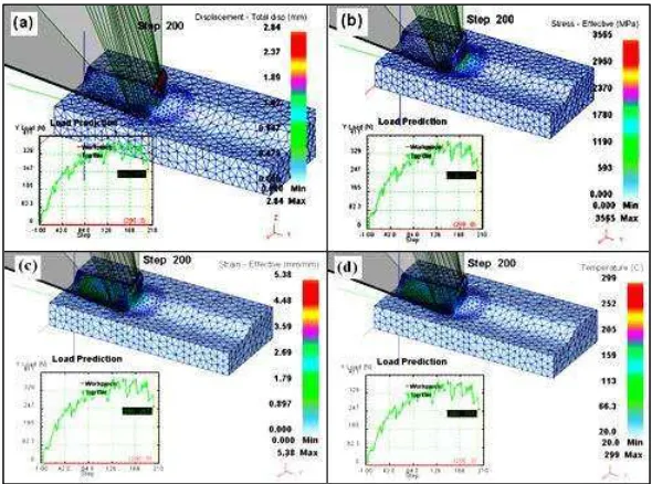
Primary and Secondary Deformation Zone. Fig. 4 shows the simulation results for displacement, cutting force, effective stress, strain and generated temperature for rake angle of +20 deg and clearance angle of 5 deg (cutting speed of 200 m/min, feed rate of 0.35 mm/rev and DOC of 3 mm) The biggest displacement was reached around 2.84 mm in total displacement at the end of chip formation (Fig. 4a). The biggest deformation was occurred on the primary deformation zone, followed by the secondary deformation zone. This also causes higher stress occurred on this area, about 3565 MPa in primary shear zone (Fig.4b). These results are agreeable with Kalhori [9], where the major deformation during cutting process were concentrated in two region close to the cutting tool edge, and the bigger deformation were occurred in the primary deformation zone, followed by secondary deformation zone, sliding region and sticking region.
Fig. 4 Simulation results for cutting speed of 200 m/min, rake angle of +20 deg and clearance angle of 5 deg), a) Displacement, b) Effective
stress, c) Effective Strain and c) Generated temperature.
1037 Advances in Materials and Processing Technologies II
Fig. 4c shows the highest effective strain occurred on primary shear zone about 5.03 mm/mm, and then followed by secondary shear zone about less than 2.69 mm/mm. And, the highest temperature was occurred at sliding region on primary shear zone around 299 oC as shown in Fig 4d. Table 3 shows the simulation results for all various rake and clearance angle where cutting speed, feed rate and depth of cut (DOC) that were kept constant at 200 m/min, 0.35 mm/rev and 3 mm respectively.
Table 3: The result of simulation for cutting force, stress, strain, and temperature
No Rake strain and generated temperature are decreasing as shown in Fig. 5a, 5b, 5c and 5d respectively. For example, increasing the rake angle from +15 deg to +20 deg, will reduce the cutting force from 346 N to 239 N, stress from 4320 MPa to 3565 MPa, strain from 6.11 to 5.03 mm/mm and temperature from 321 oC to 299 oC. This can be accepted that the reducing in cutting force, stress, strain and temperature were resulted from reduction of tool/chip contact area, so the cutting force and friction are expected to be decreased. This is agreeable with theory and experiment done by Gunay et al
Fig. 5 Effect of rake angle, (a). rake angle vs cutting force, (b). rake angle vs stress, (c). rake angle vs strain, and (d). rake angle vs
1038 Advances in Materials and Processing Technologies II
face will rub against the freshly cut metal surface. In industry, the clearance angle is varied, but often in the order of 6 – 10 deg [11].
Conclusion
The distribution of cutting force, effective stress and generated temperature obtained from simulations are agreeable with the results given in literature. From the simulation, it can be concluded that increasing the rake angle (α) in the turning of ductile cast iron using tungsten carbide (CW), it will improves the machining performance by reducing the cutting force, stress, strain and generated temperature. But, by increasing the clearance angle (γ), it will not influence much to the cutting force, stress, strain and generated temperature on chip.
References
[1] T.D. Marusich and Ortiz: Modeling and Simulation of High-Speed Machining, To appear: International Jour. Num. Metallurgy Engineering. (1995).
[2] A. E. Cerenitti, B.P. Fallbohmer, W. Wu C.W and Altan B.T: Application of 2D FEM to Chip Formation in Orthogonal Cutting, Jour. of materials Processing Technology Vol. 59
(1996), p.169-180.
[3] J. Q. Xie, A. E. Bayoumi, and H. M. Zbib: FEA Modelling and Simulation of Shear Localized Chip Formation in Metal Cutting, Jour. of Materials Processing Technology Vol. 38
(1998), p.1067-1087.
[4] C. Shet: Finite Element Analysis of the Orthogonal Metal Cutting Process, Jour. of Materials Processing Technology Vol. 105 (2000), p. 95-109
[5] A.E.Cerenitti, C.Lazzaroni, L.Menegardo and B.T.Altan: Turning Simulation Using a Three- Dimensional FEM Code, Jour. of materials Processing Technology Vol. 98 (2000), p.99-103. [6] O.H.Columbus, in : DeformTM - 3D Machining (Turning) Lab, Scientific Forming Tech. Corporation (2007).
[7] J. Mackerle: Finite Element Analysis and Simulation of Machining: a Bibliography (1976 – 1996), Jour. of Materials Processing Technology Volume 86 (1999), p. 17-44.
[8] P. L. B. Oxley, in: Mechanics of Machining: An Analytical Approach to Assessing Machinability, Ellis Horwood, Chichester, West Sussex (1989), p. 223–227
[9] V. Kalhori, in: Modelling and Simulation of Mechanical Cutting, Doctoral Thesis, Institutionen for Maskinteknik, Sweden (2001).
[10] M. G. Gunay, I. Korkut, E. Aslan and U. S. Eker: Experimental investigation of the effect of cutting tool rake angle on main cutting force, Jour. of Materials Processing Technology Vol. 166 (2005), p. 44–49.
[11] E. M. Trent, in: Metal Cutting, Butterworth - Heinmann Ltd, London (1991). Fig. 6 Effect of clearance angle, (a) clearance angle vs cutting Speed, (b) clearance
1033 Advances in Materials and Processing Technologies II
Adv a n ce d M a t e r ia ls Re se a r ch ( Volu m e s 2 6 4 - 2 6 5 )
Alamat web: http://www.scientific.net/AMR.264-265.1033
1034 Advances in Materials and Processing Technologies II
Ed itors Hu , X.Z.
The Universit y of Western Aust ralia, School of Mechanical and Chem ical Engineering; Applied Mechanics & Advanced Materials Group, Pert h, Aust ralia, WA 6009;
Lau , A.K.T. Send m ail
Hong Kong Polytechnic Universit y, Departm ent of Mechanical Engineering; Hung Hom , Kowloon, Hong Kong, China;
Publishing Edit or Wohlbier , T. Send m ail
105 Springdale Lane, Millersville, United St at es of Am erica, PA 17551;
Ed itor ia l Boa rd Bart on , J.
Send m ail
Universit y of Sout ham pt on, School of Engineering Sciences; Highfield, Sout ham pt on, United Kingdom , SO17 1BJ;
Cao , P. Send m ail
Universit y of Waikat o, Departm ent of Mat erials and Process Engineering, Waikat o Cent re for Advanced Mat erials; Privat e Bag 3105, Ham ilt on, New Zealand, 3240;
Chandra , T. Send m ail
Universit y of Wollongong, Facult y of Engineering, School of Mechanicals, Mat erials and Mechat ronic Engineering; 33 Boot ie St reet, Wollongong, Aust ralia, NSW 2522;
Chicinaş , I. Send m ail
Technical Universit y of Cluj - Napoca, Departm ent of Mat erials Science and Technology; 103- 105 Muncii Blv., Cluj - Napoca, 400641, Rom ania;
Daniel , B.S.S. Send m ail
I ndian I nst it ute of Technology Roorkee, Departm ent of Metallurgical and Materials Engineering, Cent re of Nanotechnology; Roorkee, I ndia, 247 667;
Engel , U. Send m ail
Friedrich- Alexander- Universit ät Erlangen- Nürnberg, Chair of Manufact uring Technology; Egerlandst rasse 11- 13, Erlangen, 91058, Germ any;
Evans , S.L. Send m ail
Cardiff Universit y, Cardiff School of Engineering; Queen's Buildings, P.O.Box 925 Parade, Newport Road, Cardiff, United Kingdom , CF24 3AA;
Gao , H. Send m ail
Dalian Universit y of Technology, School of Mechanical Engineering; Dalian, Liaoning, China, 116024;
I bhadode , A.O.A. Send m ail
1035 Advances in Materials and Processing Technologies II
Jha , P.K. Send m ail
Bhavnagar Universit y, Departm ent of Physics; Bhavnagar, I ndia, 364001;
Kim , J.K. Send m ail
Hong Kong Universit y of Science and Technology, Departm ent of Mechanical Engineering; Clear Wat er Bay, Pokfulam Road Kowloon, Hong Kong, China;
Leng , J.S. Send m ail
Harbin I nst it ute of Technology, Center for Com posite Materials and St ruct ures; BLDG. A, Science Park of Harbin I nst it ut e of Technology, No. 2 Yikuang St reet Nangang DI ST., Harbin, Heilongj iang, China, 150080;
Palkowski , H. Send m ail
Claust hal Universit y of Technology, I nst it ute of Met allurgy; Robert- Koch-St rasse 42, Claust hal- Zellerfeld, 38678, Germ any;
Pullin , R. Send m ail
Cardiff Universit y, Cardiff School of Engineering; Queen's Buildings, P.O.Box 925 Parade, Newport Road, Cardiff, United Kingdom , CF24 3AA;
Sand , W. Send m ail
Universit y of Duisburg- Essen, Biofilm Cent re, Aquat ic Biot echnology; Geibelst rasse 41, Duisburg, 47057, Germ any;
Schikorra , M. Send m ail
Technical Universit y of Dortm und, I nst itut e of Form ing Technology and Light weight Const ruct ion ( I UL); Baroper St reet 301, Dort m und, 44227, Germ any;
Yin , Y.S. Send m ail
Shanghai Marit im e Universit y, I nst itute of Marine Materials Science and Engineering; 1550 Harbor Ave, Lingang New Cit y, Shanghai, China, 200135;
Zhang , D.L. Send m ail
Universit y of Waikat o, Waikat o Cent re for Advanced Materials (WaiCAM) , School of Engineering; Private Bag 3105, Ham ilt on, New Zealand, 3240;
Zhang , T.Y. Send m ail
1033 Advances in Materials and Processing Technologies II
DAFTAR ISI
10/8/2017 Application of FEM in Investigating Machining Performance
The two biggest problems that often experienced in machining cast iron are poor machinability and high hardness. Up to now, many researchers have investigated machining performance and how to nd optimum condition in machining ductile cast iron. This study aims to investigate the machining performance of ductile cast iron and carbide cutting tool using FEM. Performances were evaluated by changing the cutting tool geometries on the machining responses of cutting force, stress, strain, and generated temperature on the workpiece. Deform-3D commercial nite element software was used in this study. Ductile cast iron FCD 500 grade was used as the work piece material and carbide insert DNMA432 type with WC (Tungsten) was used for the cutting tool. The e ects of rake and clearance angles were investigated by designing various tool geometries. Various combination of carbide insert geometries were designed using Solid Work to produce +15, +20 and +30 deg for rake angle and 5, 7, 8 and 9 deg for clearance angle. Machining condition for the simulations were remained constant at cutting speed of 200 m/min, feed rate of 0.35 mm/rev, and depth of cut of 0.3 mm. The results of e ective-stress, strain and generated temperature on both chip and material surface were analysed. The results show that by increasing the rake angle (α), it will improves the machining performance by reducing the cutting force, stress, strain and generated temperature on surface of workpiece. But, by increasing the clearance angle (γ), it will not a ect much to the cutting force, stress, strain and generated temperature on chip.
Application of FEM in Investigating Machining Performance
Periodical: Advanced Materials Research (/AMR) (Volumes 264-265)
Main Theme: Advances in Materials and Processing Technologies II (/AMR.264-265)
Edited by: M.S.J. Hashmi, S. Mridha and S. Naher
Pages: 1033-1038
DOI: 10.4028/www.scienti c.net/AMR.264-265.1033
Citation: H. Yanda et al., "Application of FEM in Investigating Machining Performance", Advanced
Materials Research, Vols. 264-265, pp. 1033-1038, 2011
Online since: June 2011
Authors: Hendri Yanda (/author/Hendri_Yanda), Jaharah A. Ghani (/author/Jaharah_A_Ghani_1), Che
Hassan Che Haron (/author/Che_Hassan_Che_Haron)
Keywords: Clearance Angle (/keyword/Clearance_Angle), Finite Element Model (FEM)
(/keyword/Finite_Element_Model_FEM), Machining Performance
(/) 中文 (https://zh.scienti c.net/AMR.264-265.1033)
(/Payment/Cart) (/ACCOUNT/LOGIN?LOG IN
10/8/2017 Application of FEM in Investigating Machining Performance
https://www.scientific.net/AMR.264-265.1033 2/2
References
Cited by
Related Articles
GET ACCESS (/ACCOUNT/SUBSCRIPTIONS) SYSTEM GUIDE (/INFO)
DISTRIBUTORS (/DISTRIBUTOR) SUPPLEMENTS (/DOWNLOADS) ABOUT US (/HOME/ABOUTUS)
POLICY & ETHICS (/HOME/MISCONDUCT) CONTACT US (/HOME/CONTACTS)
IMPRINT & PRIVACY POLICY (/HOME/IMPRINTANDPRIVACYPOLICY) SITEMAP (/HOME/SITEMAP)
10/8/2017 Advanced Materials Research
Irregular: approx. 4-6 Volumes per year. Rates 2018 for:
- Web only: EUR 560,00 per year,
- Print (+free WEB): EUR 560,00 (+Postage EUR 102,00) About:
“Advanced Materials Research” is a peer-reviewed journal which covers all aspects of theoretical and practical research of materials science: synthesis, analysis of properties, technologies of materials processing and their use in modern manufacturing. “Advanced Materials Research” is one of the largest periodicals in the eld of materials engineering.
“Advanced Materials Research” specializes in rapid publication of thematically complete volumes from international conference proceedings and complete special topic volumes. We do not publish stand-alone papers by individual authors.
Authors retain the right to publish an extended and signi cantly updated version in another periodical.
Abstracted/Indexed in:
SCImago Journal & Country Rank (SJR) www.scimagojr.com. Inspec (IET, Institution of Engineering Technology) www.theiet.org. Chemical Abstracts Service (CAS) www.cas.org.
Google Scholar scholar.google.com.
GeoRef www.americangeosciences.org/georef. Cambridge Scienti c Abstracts (CSA) www.csa.com. ProQuest www.proquest.com.
Ulrichsweb www.proquest.com/products-services/Ulrichsweb.html. EBSCO Discovery Service https://www.ebscohost.com/discovery. CiteSeerX citeseerx.ist.psu.edu.
Zetoc zetoc.jisc.ac.uk.
EVISA http://www.speciation.net/Public/Linklists/EVISA.html. Index Copernicus Journals Master List www.indexcopernicus.com. WorldCat (OCLC) www.worldcat.org.
ISSN print 1022-6680 ISSN cd 1022-6680 ISSN web 1662-8985
Additional Information:
Please ask for additional information: amr@scienti c.net (mailto:amr@scienti c.net)
(/AMR/rss)
(/) 中文 (https://zh.scienti c.net/AMR/details)
(/Payment/Cart) (/ACCOUNT/LOGIN?LOG IN
10/8/2017 Advanced Materials Research
https://www.scientific.net/AMR/details 2/2
Share: 263
GET ACCESS (/ACCOUNT/SUBSCRIPTIONS) SYSTEM GUIDE (/INFO)
DISTRIBUTORS (/DISTRIBUTOR) SUPPLEMENTS (/DOWNLOADS) ABOUT US (/HOME/ABOUTUS)
POLICY & ETHICS (/HOME/MISCONDUCT) CONTACT US (/HOME/CONTACTS)
IMPRINT & PRIVACY POLICY (/HOME/IMPRINTANDPRIVACYPOLICY) SITEMAP (/HOME/SITEMAP)
10/8/2017 Advanced Materials Research
http://www.scimagojr.com/journalsearch.php?q=4700151906&tip=sid&clean=0 1/3
Scimago Journal & Country Rank
Home Journal Rankings Country Rankings Viz Tools Help About Us
Advanced Materials Research
Scope Advanced Materials Research specializes in the very rapid publication of international conference proceedings and stand-alone volumes on topics of current interest in All areas of materials research. Indexed by Elsevier: SCOPUS www.scopus.com and Ei Compendex (CPX) www.ei.org/. Cambridge Scienti c Abstracts (CSA) www.csa.com, Chemical Abstracts (CA) www.cas.org, Google and Google Scholar google.com, ISI (ISTP, CPCI, Web of Science) www.isinet.com, Institution of Electrical Engineers (IEE) www.iee.org, etc. (source)
Enter Journal Title, ISSN or Publisher Name
Quartiles
The set of journals have been ranked according to their SJR and divided into four equal groups, four quartiles. Q1 (green) comprises the quarter of the journals with the highest values, Q2 (yellow) the second highest values, Q3 (orange) the third highest values and Q4 (red) the lowest values.
Category Year Quartile
The SJR is a size-independent prestige indicator that ranks journals by their 'average prestige per article'. It is based on the idea that 'all citations are not created equal'. SJR is a measure of scienti c in uence of journals that accounts for both the number of citations received by a journal and the importance or prestige of the journals where such citations come from It measures the scienti c in uence of the average article in a journal, it expresses how central to the global
Citations per document
This indicator counts the number of citations received by documents from a journal and divides them by the total number of documents published in that journal. The chart shows the evolution of the average number of times documents published in a journal in the past two, three and four years have been cited in the current year. The two years line is equivalent to journal impact factor
™ (Thomson Reuters) metric.
Cites per document Year Value
Cites / Doc. (4 years) 2006 0.343 Cites / Doc. (4 years) 2007 0.225 Cites / Doc. (4 years) 2008 0.279 Total Cites Self-Cites
Evolution of the total number of citations and journal's self-citations received by a journal's published
2006 2007 2008 2009 2010 2011 2012 2013 2014 2015 2016
Engineering (miscellaneous)
2006 2008 2010 2012 2014 2016
10/8/2017 Advanced Materials Research
http://www.scimagojr.com/journalsearch.php?q=4700151906&tip=sid&clean=0 2/3
Developed by: Powered by:
Follow us on Twitter
Scimago Lab, Copyright 2007-2017. Data Source: Scopus®
Cites per document Year Value
Cites / Doc. (4 years) 2009 0.216 Cites / Doc. (4 years) 2010 0.222 Cites / Doc. (4 years) 2011 0.215 Cites / Doc. (4 years) 2012 0.137 Cites / Doc. (4 years) 2013 0.119 Cites / Doc. (4 years) 2014 0.108
documents during the three previous years.
Journal Self-citation is de ned as the number of citation from a journal citing article to articles published by the same journal.
Cites Year Value
External Cites per Doc Cites per Doc
Evolution of the number of total citation per document and external citation per document (i.e. journal self-citations removed) received by a journal's published documents during the three previous years. External citations are calculated by subtracting the number of self-citations from the total number of citations received by the journal’s documents.
Cites Year Value
% International Collaboration
International Collaboration accounts for the articles that have been produced by researchers from several countries. The chart shows the ratio of a journal's documents signed by researchers from more than one country; that is including more than one country address.
Year International Collaboration
2006 7.90
2007 13.27
Citable documents Non-citable documents
Not every article in a journal is considered primary research and therefore "citable", this chart shows the ratio of a journal's articles including substantial research (research articles, conference papers and reviews) in three year windows vs. those documents other than research articles, reviews and conference papers.
Documents Year Value
Non-citable documents 2006 2
Cited documents Uncited documents
Ratio of a journal's items, grouped in three years windows, that have been cited at least once vs. those not cited during the following year.
Documents Year Value
<a href="http://www.scimagojr.com/journalsearch.php?q=4700151906&tip=sid&exact=no" title="SCImago Journal & Country Rank"><img border="0" src="http://www.scimagojr.com/journal_img.php?id=4700151906" alt="SCImago Journal & Country Rank" /></a>
0.24 0.3 0.36
5k 10k
2006 2008 2010 2012 2014 2016
0 0.2 0.4
2006 2008 2010 2012 2014 2016
0 7.5 15
2006 2008 2010 2012 2014 2016
0 50k 100k
2006 2008 2010 2012 2014 2016
10/8/2017 Advanced Materials Research
10/8/2017 Application of FEM in Investigating Machining Performance - Repositori Universitas Andalas
http://repo.unand.ac.id/3984/ 1/1
Application of FEM in Investigating Machining Performance
Hendri, Yanda and Jaharah, A. Ghani and Che, Hassan Che Harun Application of FEM in Investigating Machining Performance.
Application of FEM in Investigating Machining Performance. pp. 1033-1038. ISSN 1662-8985 Text (Application of FEM in Investigating Machining Performance)
Application of FEM in Investigating Machining Performance.pdf Download (1MB) | Preview
Abstract
The two biggest problems that often experienced in machining cast iron are poor machinability and high hardness. Up to now, many researchers have investigated machining performance and how to find optimum condition in machining ductile cast iron. This study aims to investigate the machining performance of ductile cast iron and carbide cutting tool using FEM. Performances were evaluated by changing the cutting tool geometries on the machining responses of cutting force, stress, strain, and generated temperature on the workpiece. Deform-3D commercial finite element software was used in this study. Ductile cast iron FCD 500 grade was used as the work piece material and carbide insert DNMA432 type with WC (Tungsten) was used for the cutting tool. The effects of rake and clearance angles were investigated by designing various tool geometries. Various combination of carbide insert geometries were designed using Solid Work to produce +15, +20 and +30 deg for rake angle and 5, 7, 8 and 9 deg for clearance angle. Machining condition for the simulations were remained constant at cutting speed of 200 m/min, feed rate of 0.35 mm/rev, and depth of cut of 0.3 mm. The results of effective-stress, strain and generated temperature on both chip and material surface were analysed. The results show that by increasing the rake angle (α), it will improves the machining performance by reducing the cutting force, stress, strain and generated temperature on surface of workpiece. But, by increasing the clearance angle (γ), it will not affect much to the cutting force, stress, strain and generated temperature on chip.
Item Type: Article
Subjects: A General Works > AS Academies and learned societies (General)T Technology > T Technology (General) T Technology > TA Engineering (General). Civil engineering (General)
Divisions: Fakultas Teknik
Depositing User: sry sartika
Date Deposited: 04 Nov 2016 03:01
Last Modified: 04 Nov 2016 03:01
URI: http://repo.unand.ac.id/id/eprint/3984
Actions (login required)