P. Pudjisuryadi1, B. Lumantarna1*, S. Teddy2, and H.Wijoyo1
1
Department of Civil Engineering, Petra Christian University, Surabaya, Indonesia
2
Design Engineer Benjamin Gideon and Associates, Surabaya, Indonesia *e-mail of corresponding author: [email protected]
ABSTRACT
A new design method named the Partial Capacity Design Method (PCDM) has been proposed by the Authors. In this method partial side sway mechanism is employed, in which for a certain seismic load level some columns are allowed to develop plastic hinges while some selected columns are to remain elastic except at the base of the structure. To ensure these selected columns remain elastic, these columns are designed to resist magnified internal forces. The internal forces due to the nominal earthquake load are multiplied by a certain magnification factor, f. Several efforts have been made to find the suitable magnification factor, f. In the latest development the determination of the magnification factor, f, is based on the natural period of the structure in plastic condition, “the plastic period”, Tpl. The plastic period, Tpl is predicted using a correlation between the elastic and plastic natural period developed from data of several structures previously observed. The performance of several symmetrical fully ductile concrete moment resisting frame designed in accordance with the latest Indonesian Seismic Code (SNI 03 1726-2002) using the proposed method has been presented elsewhere. In this paper some structures with vertical set-back are designed with PCDM and the seismic performances are evaluated using dynamic non-linear time history analysis. The results show that under the intended seismic load level, the selected columns remain elastic and the structures performed very well as suggested in the Asian Concrete Model Code (ACMC).
Keywords: Capacity Design Method, Partial Capacity Design Method, magnification factor, seismic performance.
1. INTRODUCTION
The Capacity Design Method (CDM) is a well accepted design procedure for earthquake resistant design. CDM employs “strong column-weak beam” design philosophy where the failure mechanism expected is the so called Side Sway Mechanism (Figure 1). Applying CDM implies that the columns can not be designed before the beams are designed. This is not very practical in real world of design practice.
Several efforts have been made to overcome this shortcoming (Lumantarna et.al.,1994, 1997, 1998,2004: Chandra and Dhannyanto, 2003; Saputra and Soegiarto, 2005). Muljati and Lumantarna (2007, 2008) explored and suggested alternative design methods called Partial Capacity Design Method (PCDM) which allowed partial side sway mechanism, shown in Figure 2 (Paulay, 1995) instead of side sway mechanism (Fig. 1). In the proposed method, plastic hinges were allowed to develop in the interior columns, while no plastic hinge was allowed in the exterior columns, except at the bottom. The perimeter columns were designed to resist magnified internal forces due to the nominal earthquake load multiplied by a certain magnification factor. Muljati and Lumantarna (2007, 2008) developed a certain formula to obtain a magnification factor, f, to be used in increasing the perimeter columns strength.
Recently Muljati and Lumantarna (2011) applied PCDM to structures with vertical set-back and reported that plastic hinges developed in some “elastic perimeter” columns. The present authors suspect that since the magnification factor formula is developed based on a certain design practice, the failure could be caused by “improper” design practice. The present authors revisit the structures used by Muljati and Lumantarna (2011) and refined the design.
2. PARTIAL CAPACITY DESIGN
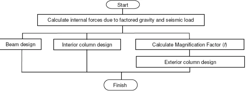
PCDM offers some convenience compared to the CDM because columns can be designed before the design of beams is completed. The design procedure of PCDM is shown in Figure 3.
Figure 3. Flowchart of PCDM
2.1. Magnification factor, f
Assuming that the interior columns can only take the shear force due to the nominal seismic load and the reserve strength of the structure, Muljati and Lumantarna (2008, 2009) proposed the magnification factor, f, for the exterior column as follows:
STex = SNex * f , where
where STex is the shear force in the individual exterior column due to the target seismic load; SNex the shear
force in the individual exterior column due to the nominal seismic load; nex the total number of the exterior
column; nin the total number of the interior column; RNin and RNexare respectively the ratio of the interior
and exterior columns’ base shear to the total base shear due to the nominal seismic load. Target seismic load can be defined as the level of seismic load where the structure is expected to be in the safety limit state. Further, CT and C500 are the spectral acceleration due to the target seismic load and five hundred years return period earthquake respectively and μ the structure’s ductility.
2.2. Target Spectral Acceleration, CT
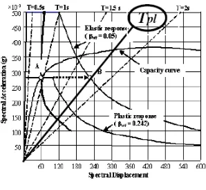
Since during the application of the target seismic load the structure is expected to be already in the non-linear stage, the target spectral acceleration CT should be obtained from the non-linear/plastic response spectrum. The non-linear response spectrum can be generated if the effective damping factor, βeff, can be predicted (ATC40, 1996). Alternately CT can also be obtained if one can predict the period of the structure in the non-linear stage (plastic period, Tpl). Figure 4 shows the typical result of a static pushover non-linear analysis using the Capacity Spectrum Method (ATC40, 1996).
Figure 4 shows the elastic response spectrum of the target seismic load and reduced “plastic” response spectrum (demand spectrum). The intersection between the capacity spectrum and demand spectrum, “the performance point” is labeled as point A. The demand spectrum in this case is an elastic response spectrum considering effective damping βeff, due to plasticity, thus “the plastic response spectrum”. In Figure 4, the plastic response spectrum has an effective damping coefficient βeff, of 0.242. The intersection of a horizontal line draws from point A with the ordinate gives the plastic spectral acceleration
plastic natural period (Teland Tpl respectively) of previous structures suggested a correlation between the elastic and the plastic natural period as:
Tpl = 2.969 Tel + 0.313...(2)
Figure 4. Development of Tpl
3. SEISMIC PERFORMANCE OF BUILDING DESIGNED WITH THE PCDM
In this study buildings with vertical set-back used by Muljati and Lumantarna (2011) were redesigned. Figure 5 shows the plan and elevation of the ten-story building. Columns 2-B,C,D; 3-B,D; and 4-B,C,D are selected to be the elastic columns. These buildings are assumed to be built in Zone 6 of the Indonesian Earthquake code (SNI 03 1726-2002).
Figure 5. Structural Plan and Elevation of ten-story building
The present study refines the beam design, for example, the beams connected to column C8 (indicated by circle in the structural plan) at the level of setback are refined as shown in Table 1.
Table 1. Comparison of the reinforcements used in this study and the previous study (Muljati and Lumantarna, 2011)
Present study Muljati and Lumantarna (2011) Beam connected to C8 Location
Left Right Left Right
Top 6D19 11D19 12D19 12D19
B11
Bottom 3D19 6D19 6D19 6D19
Top 13 D19 12D19 14D19 14D19
B19
Bottom 7D19 6D19 8D19 8D19
Top 12D19 13D19 14D19 14D19
B20
Bottom 6D19 7D19 8D19 8D19
Top 13D19 8D19 14D19 14D19
B28
Bottom 7D19 4D19 8D19 8D19
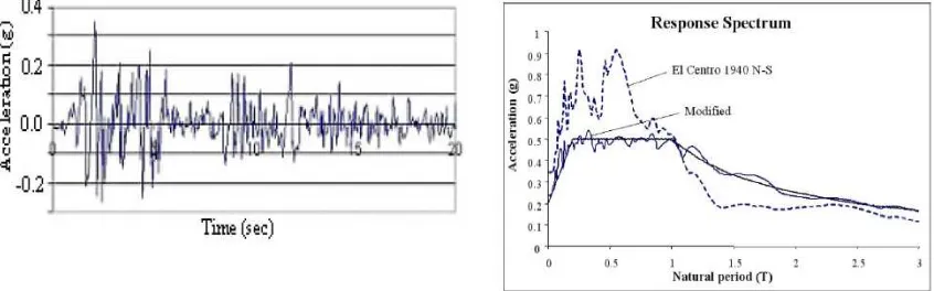
The performance of these buildings are tested to static non-linear pushover analysis (ATC40, 1996, Krawinkler, 1994, 1996, Boen, 1999) and the non-linear time history analysis. The static non-linear pushover analysis is performed using ETABS-nonlinear (Habibullah, 1998) with lateral load based on first mode shape. The non-linear time history analysis is performed using RUAUMOKO 3D (Carr, 2001, 2002). The hinge properties of the beams and columns are obtained using ESDAP (Lidyawati and Pono, 2003) a program developed at Petra Christian University, Surabaya based on the algorithm proposed by D.J. King (1986). The ground acceleration used for the time history analysis is spectrum consistent ground acceleration modified from the N-S component of El-Centro 1940. The modification is achieved using RESMAT (Lumantarna and Lukito, 1997), a program developed at Petra Christian University, Surabaya. The modified ground acceleration and the response spectrum are shown in Figure 6 respectively.
Figure 6. Modified seismic record and the response spectrum
3.1. Plastic Hinges Location
Figures 7 and 8 show typical result of the analysis showing the plastic hinges location due to the application of a 500 years return period ground acceleration, which is also the target seismic load in this case. Complete information can be found in Wijoyo and Teddy (2011). Figure 7(a) and (b) show the plastic hinges location on the exterior frame of a ten-story four-bay (H-10.4) building as analyzed using the static non-linear pushover analysis and the non-linear time history analysis respectively. Figure 8(a) and (b) plastic hinges on the interior frame of the same building. Dots in figures represent plastic hinges and numbers represent damage indices.
(a) Pushover (b) Time History
(a) Pushover (b) Time History
Figure 8. Plastic hinges on Interior Frame of 10-story 4-bay building (H-10.4)
3.2. Displacement and Drift
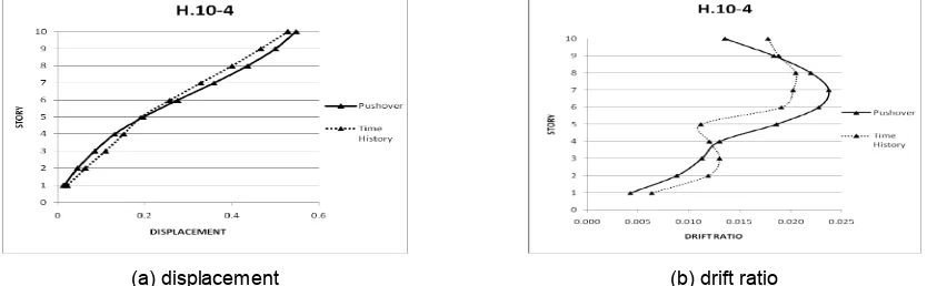
Figure 9 shows typical result of the deformations of the structures due to the target seismic load, which in this case is set as a 500 years return period ground acceleration. Figure 9(a) and (b) show respectively, the displacement and drift ratio of the ten-story four-bay building (H-10.4) as analyzed using the static non-linear pushover analysis and the non-non-linear time history analysis.
(a) displacement (b) drift ratio
Figure 9. Displacement and drift ratio of 10-story 4-bay building (H-10.4)
4. CONCLUSION
The results of this research show that no plastic hinges occurred in elastic columns at the target earthquake (500 years return period ground acceleration), thus the partial side sway mechanism is well satisfied. However, since the collumns are not designed using the capacity of the beams connected to them, one should be very careful and not place excessive reinforcement in the beams instead only minimum round ups should be applied.
5. REFERENCES
[1] ATC 40, 1996, Seismic Evaluation and Retrofit of Concrete Buildings, Volume I. Applied Technology Council, California, USA.
[2] Atmadja, K.G. and Wijaya, B., 2009, Evaluasi Kinerja Bangunan Dengan Metode Pseudo Elastis pada
Wilayah 6 Peta Gempa Indonesia, Undergraduate Theses, Civil Engineering Department, Petra
Christian University, Surabaya, Indonesia.
[3] Boen, T., 1999, Dasar-dasar Analisa Pushover, Proc. Seminar Nasional Teknik Sipil, Universitas Katolik Parahyangan, Bandung, Indonesia, pp. 2.01-2.14.
[4] Buntoro, I.Y. and Welyianto,A., 2009, Evaluasi Kinerja Bangunan Dengan Metode Pseudo Elastis pada
Wilayah 2 Peta Gempa Indonesia, Undergraduate Theses, Civil Engineering Department, Petra
Christian University, Surabaya, Indonesia
[6] Carr, A.J., 2002, Ruaumoko Computer Program Library. University of Canterbury, New Zealand.
[7] Chandra, A. and Dhannyanto, 2003, Alternatif Perencanaan Struktur Rangka Beton Bertulang dengan
Pseudoelastis, Undergraduate Theses, Civil Engineering Department, Petra Christian University,
Surabaya, Indonesia.
[8] Habibullah, A., 1998, ETABS, Three Dimensional Analysis and Design of Building Systems, Computer
and Structures, Inc., Berkeley, California, USA.
[9] King, D.J., 1986, Computer Programs for Concrete Column Design, Research Report, University of Canterbury, New Zealand.
[10] Krawinkler, H. 1994, Static Pushover Analysis, SEAONC 1994 Fall Seminar on The Developing Art of
Seismic Engineering, California, USA, pp. 1-24.
[11] Krawinkler, H. 1996, Pushover Analysis: Why, How, When and Where Not to Use It, Proc. 65th Annual Convention SEAOC, Maui, Hawaii, USA, pp. 17-36.
[12] Kusuma, A. and Wibowo, Z.Y., 2008, Evaluasi Kinerja Struktur 4 dan 10 Lantai yang Didesain Sesuai
Pseudo Elastis dan SNI 03-2847-2002 di Wilayah 6 Peta Gempa Indonesia. Undergraduate Theses,
Civil Engineering Department, Petra Christian University, Surabaya, Indonesia.
[13] Lidyawati, and Pono, G.B.W., 2003, Penyempurnaan Program Komputer untuk Desain Beban Lentur
dan Aksial serta Analisa Momen Kurvatur Penampang Beton Bertulang, Undergraduate Theses, Civil
Engineering Department, Petra Christian University, Surabaya, Indonesia.
[14] Lumantarna, B., 1998, Batasan Pemakaian Perencanaan Pseudo Elastis Menggunakan Satu Pasang
Kolom Tepi, Dimensi, vol 23/sip, April 1998, pp. 60-65.
[15] Lumantarna, B. and Francica, C., 1994, Perencanaan Kapasitas Alternatif, Suatu Studi Pendahuluan,
Proc. of the International Conference on Modern Design and Construction for Safety, Economy, and Durability, Petra Christian University, Surabaya, Indonesia.
[16] Lumantarna, B. and Lukito, M., 1997, Resmat, Sebuah Program Interaktif untuk Menghasilkan Riwayat
Waktu Gempa dengan Spektrum Tertentu, Proc. HAKI Conference 1997, Jakarta, Indonesia, pp.
128-135.
[17] Lumantarna, B., Andriono, T., Chandra, A., Dhannyanto. 2004, Alternatives to the capacity design
method, a preliminary proposal, Proc. of the 18th Australasian Conference on the Mechanics of
Structures and Material; ACMSM18, Perth, 1-3 December 2004. Leiden: Balkema.
[18] Lumantarna, B., Tindrawati, and Wijaya, J, 1997, Studi Pendahuluan tentang Perencanaan Seismic
Beton Bertulang Menggunakan Metode Pseudo Elastis, HAKI Conference on Civil and Structural
Engineering, Jakarta, Indonesia, pp. 102-115.
[19] Muljati, I. and Lumantarna, B., 2007, Partial capacity design, an alternative to the capacity design
method”, Proceedings of the 19th Australasian Conference on the Mechanics of Structures and
Materials; ACMSM19, Christchurch, New Zealand, pp. 409-414.
[20] Muljati, I. and Lumantarna, B., 2008, Performance of partial Capacity Design on Fully Ductile Moment
Resisting Frame in Highly Seismic Area in Indonesia, Eleventh East Asia-Pacific Conference on
Structural Engineering & Construction (EASEC-11) “Building a Sustainable Environment”, Taipei, TAIWAN.
[21] Muljati, I. and Lumantarna, B., 2009, Partial Capacity Design, An Alternative to The Capacity Design
Method, guest lecture on 17 July 2009 in Carleton University, Ottawa, Canada
[22] Muljati, I. and Lumantarna, B., 2011, Seismic Performance of Structure with Vertical Geometric
Irregularity Designed Using Partial Capacity Design, to be presented on 19 July 2011 in 2nd
International Conference on Earthquake Engineering and Disaster Mitigation (ICEEDM), Surabaya, Indonesia.
[23] Paulay, T., 1995, Special Issues in Seismic Design, Structural Engineering International, Volume 5: 160-165.
[24] Reni, S. and Tirtalaksana, I., Evaluasi Kinerja Struktur 6 dan 8 Lantai yang Didesain Sesuai Pseudo
Elastis dan SNI 03-2847-2002 di Wilayah 6 Peta Gempa Indonesia, Undergraduate Theses, Civil
Engineering Department, Petra Christian University, Surabaya, Indonesia.
[25] Saputra, R.H. and Soegiarto, A., 2005, Penentuan Faktor Pengali untuk Perencanaan Pseudo Elastis
pada Struktur Rangka Penahan Momen Khusus, Undergraduate Theses, Civil Engineering
[26] SNI 03 1726-2002, Standar Perencanaan Ketahanan Gempa untuk Struktur Gedung, SNI 03 1726,
Departemen Pemukiman dan Prasarana Wilayah, Bandung, Indonesia.
[27] Susanto, T., 2009, Studi Faktor Pengali Kapasitas Kolom Eksterior dalam Perencanaan Pseudo
Elastis, Undergraduate Theses, Civil Engineering Department, Petra Christian University, Surabaya,
Indonesia.