www.elsevier.nlrlocaterjappgeo
Development of surface-process models and correspondence principles for geophysical
anomalies
Geoelectrical investigation of old
r
abandoned, covered landfill
sites in urban areas: model development with a genetic diagnosis
approach
Maxwell A. Meju
)EnÕironmental and Industrial Geophysics Research Group, Department of Geology, UniÕersity of Leicester,
UniÕersity Road, Leicester LE1 7RH, UK Received 21 September 1998; accepted 3 March 2000
Abstract
Geoelectrical methods have an important, albeit difficult role to play in landfill investigations. In the present economic conditions, with the environmentally sensitive regime, adequate desk-study and model development are essential ingredients for a successful site investigation of landfills. This paper attempts to develop a genetic investigative model for oldraban-doned landfill sites where the records of operations are not available. The main elements of the model are the site boundaries, age and nature of anthropogenic deposits, depth and dip of the layers of refuse and sealing materials, the integrity and shape of the capping zones or separating walls and basal floor slopes, the position of concealed access roads in
Ž .
the site, the water table or perched water bodies within the refuse and the presence of leachate. The attendant geotechnical, hydrogeological, and bio-geochemical constraints at such sites are also incorporated in the model for consistency of practical solutions to landfill problems. The nature of anthropogenic deposits and the spatial–temporal characteristics of leachates are reviewed in a geoelectrical context. The analogy between waste degradation and leaching, and the well-known weathering processes of supergene mineral enrichment and saprolite formation in crystalline rocks is explored, and used to develop a conceptual resistivity-vs.-depth model for landfill sites. The main tenet of the model is that vertical conductivity profiles will attain maximum values in the zone of mineral enrichment near the water table and tail-off away from it. This conceptual resistivity model is shown to be consistent with non-invasive observations in landfill sites in different geographical environments. Power–law relationships are found to exist between some geoelectrically important hydrochemical parameters
Žfluid conductivity, chloride content and total dissolved solids in leachates and leachate-contaminated groundwater from.
some landfill sites. Since some chemical parameters of fill are known to vary consistently with time, a plausible hydrochemical and age-deductive scheme for saturated fill is proposed for geoelectrical models of landfills without significant amounts of metal. Practical suggestions are made for a consistent approach in geoelectrical investigation and diagnosis of old landfill sites. A few field examples are used to illustrate the diagnosis approach.q2000 Elsevier Science B.V. All rights reserved.
Keywords: Landfill sites; Leachate characteristics; Conceptual resistivity model; Geophysics
)Tel.:q44-116-252-3628; fax:q44-116-252-3918.
Ž .
E-mail address: [email protected] M.A. Meju .
0926-9851r00r$ - see front matterq2000 Elsevier Science B.V. All rights reserved.
Ž .
( )
M.A. MejurJournal of Applied Geophysics 44 2000 115–150
116
1. Introduction
Waste disposal by landfill is very popular, and the ever increasing demand for larger space for domestic and industrial wastes from urban areas makes them a necessary part of the human cycle of activities. Landfill sites commonly use the space available in disused quarries or spe-cial-purpose-built structures but unauthorised
Ž
waste disposal in moats defence ditches around
.
ancient city walls and dry river channels can also be found near some urban areas. These large waste containment facilities are typically polluted, hence the need for stringent statutory controls. Unfortunately, not all past landfill op-erations were adequately controlled or docu-mented such that the site boundaries, and the type and volume of fill are unknown in some covered landfill sites. Moreover, even in con-trolled sites, the final form and depth extent of the landfill may not conform to those indicated in the original plan submitted to the regulatory authorities during the application for a site li-cense. Thus, a significant amount of work is required to accurately define the relevant pa-rameters of a covered landfill site.
Our interest in landfill sites may lie in assess-ing the pollution threat they pose since they may contain hazardous substances. We may also be interested in gauging their construction feasi-bility, since some old landfill sites, previously considered as unattractive or marginal building land, are now being developed for light indus-trial and domestic infrastructure as a result of the decline in heavy industrial activity and the ever increasing need for urban regeneration in many old industrialised regions. In standard landfill site investigations, the usual goals are to
Ž
determine the geometrical characteristics size
.
and shape , the physical properties and the chemical composition of the fill. Geophysics has an important albeit difficult role to play in fulfilling parts of these requirements. For exam-ple, geophysical methods can furnish useful data for locating the boundaries of a landfill site and fill thickness. Physical property distribution in
the subsurface, which may have geotechnical significance, can be derived from the geophysi-cal data. Additionally, since some geophysigeophysi-cal methods respond to changes in the physico-chemical conditions in the subsurface, useful chemical information may be gleaned from con-tinuous geophysical site monitoring investiga-tions. A few confirmatory boreholes may serve to validate the geophysically derived informa-tion.
Of the several non-invasive geophysical
Ž
methods used in landfill studies see Whiteley
.
and Jewell, 1992 , the electrical and
electromag-Ž .
netic EM methods are the most popular owing to their inherent ability to detect changes related to variations in fluid content, chemical composi-tion and temperature in the subsurface, and the minimum capital and labour outlay required to use them in small-scale surveys. Since the pres-ence of saline fluids in the ground enhances its ability to conduct electrical current, it is possi-ble to locate a contaminant plume by measuring the resistivity distribution in the subsurface. The two main ground resistivity measurement tech-niques employed in landfill or groundwater
con-Ž .
tamination studies are the direct current dc
Ž
resistivity methods e.g. Cartwright and McCo-mas,1968; Warner, 1969; Stoller and Roux, 1973; Klefstad et al., 1975; Barker, 1990, 1992; Ross et al.,1990; Carpenter et al., 1990a,b, 1991;
.
Meju, 1993, 1995a,b and transient
electromag-Ž . Ž
netic TEM methods e.g. Buselli et al., 1988,
.
1992; Meju, 1993, 1995a , but the radio- or
Ž .
audio-frequency magnetotelluric RMT or AMT method is rapidly emerging as a powerful tool
Ž .
for such investigations e.g. Tezkan et al., 1996
Ž .
and the self-potential SP method is a vital complement to these other techniques in
near-Ž
surface groundwater flow detection work e.g.
.
Ogilvy et al., 1969; Stierman, 1984 . For land-fill construction feasibility investigations, a combined approach involving the seismic
re-Ž .
are appreciable density contrasts between the fill and the surrounding geological materials
Že.g. Whiteley, 1983; Roberts et al., 1990 ,.
gravimetric techniques could be used for defin-ing the geometry and depth extent of the
land-Ž
fill. Heterogeneities within the fill e.g. metal
.
drums may be mapped using magnetometric
Ž . Ž
and ground probing radar GPR methods e.g.
.
Hinze et al., 1990 . The shallow seismic reflec-tion and GPR methods are undoubtedly the best
Ž
geological mapping tools in ideal situations e.g. Hill and Ali, 1988; Ali and Hill, 1991; Beres
.
and Haeni, 1991 but old landfill sites constitute an entirely different target in which the loose fill is typically associated with poor energy propagation and the clayey horizons limit the usefulness of radar signals.
In comparison with the traditional field tech-niques used in natural resources exploration, geoelectrical investigation of landfill sites is on a different scale and requires special attention to details. To start with, the area under investiga-tion is often geometrically constrained and be-deviled by cultural noise, yet the sampling rate and data quality requirements for target defini-tion are more stringent. The consequences of inadequate or unsuccessful site investigation may be more serious in pollution-related stud-ies, with insurance or legal connotations. Thus, in the present economic and legal climate, ade-quate desk-study and model development are essential ingredients for a successful cost-effec-tive geoelectrical investigation of old landfill sites.
The main thrust of this paper is to develop a consistent exploration model for anthropogenic deposits in oldrabandoned sites where the nec-essary record of operations is no longer avail-able or never existed, as in the case of unautho-rised dumping grounds. The model will draw from current concepts in geotechnics and con-taminant geochemistry, and stress the complex geometry of landfill sites, the heterogeneous material compositions, and the attendant com-plex biogeomorphic processes in landfill envi-ronments. The analogy between refuse
decom-position processes and weathering of geological materials will be explored, and used to guide the development of a conceptual resistivity-vs.-depth model for old covered landfill sites. The versatility of this particular model will be tested using depth soundings from various geographic regions. In line with the exciting geochemical observation that some chemical parameters of
Ž
landfill leachates vary consistently with age e.g.
.
Farquhar, 1989; DoE, 1996 , we investigate the relationships between diagnostic leachate
chem-Ž
ical parameters electrical conductivity, total
Ž . .
dissolved solids TDS and chloride content and attempt to propose a plausible practical scheme for fill-age and hydrochemical predic-tions using surface geoelectrical measurements. Some illustrative field examples will be pre-sented in support of the proposed predictive scheme.
2. Model development
2.1. Characteristics of landfill sites and anthro-pogenic deposits
Landfill sites are geotechnically classified as inert sites, urban and low-strength industrial
Ž
sites, or high strength industrial or
.
hazardousrco-disposal sites, depending on the type of fill content. Although there will be no single model that can adequately characterise all types of landfills, we will adopt a generalised approach in this paper. To understand how the attendant processes in landfill environments can influence our geoelectrical measurements, it is instructive to examine the consistent features of models derived from geological, geotechnical, biological and biogeochemical observations on
Ž .
landfills plus other contaminated lands and rock weathering that can be adopted as the basic building blocks for any geoelectrical model for
Ž
pro-( )
M.A. MejurJournal of Applied Geophysics 44 2000 115–150
118
.
cesses in harsh environmental conditions are recognised and adapted into a simplified geo-electric model in this section.
2.2. Geometry of landfill sites
Landfill sites come in various shapes, sizes and depths, and as previously mentioned, they may be located in purpose-built facilities, dis-used softrockrhardrock quarries, opencast coal mines or other convenient holes in the ground. They may be situated above, below or astride the regional water table. In some oldr aban-doned waste disposal sites, a lining of relatively impermeable material may be present, or the refuse may be in direct contact with granular or
Ž
crystalline geological materials dubbed the
ge-.
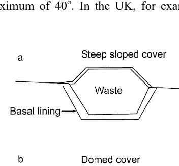
omatrix in geotechnical parlance . In landfill capping, a soil cover layer is required when returning the site to agricultural or ammenity use and steep sided cover systems are often
Ž .
incorporated in the cover design see Fig. 1 to
Ž
maximize the landfill capacity Hall and
.
Gilchrist, 1995 . The cover system could be multi-layered in sophisticated waste storage fa-cilities or single-layered in some old uncon-trolled landfills. The side slopes of cover sys-tems commonly vary from about 38 up to a maximum of 408. In the UK, for example, the
Ž .
Fig. 1. Common cover types at old landfill sites. a
Ž .
Steeply sloping side, and b domed cap.
side slopes of the lining system are often re-quired to be in excess of 208 and ‘‘doming’’ of
Ž . Ž
capping systems Fig. 1 is common Hall and
.
Gilchrist, 1995 . There may be basal floor slopes to promote leachate drainage to sumps but it can be expected that many pre-regulation landfill sites may have inadequate basal containment and leachate collection systems; there will also be cases where the landfill bottom is neither graded nor lined. Landfills generally range in thickness from about 3 to 20 m but deeper sites
Žca. 30 m are known to exist..
2.3. Nature and characteristics of anthro-pogenic deposits
Landfill deposits are characterised by plex material composition, non-uniform com-paction within each layer, non-uniform decom-position process, non-uniform settlement and
Ž .
varying pore fluid composition Fang, 1995a . The deposits may be intermixtures of domestic and industrial wastes, soils and exhumed
geo-Ž .
logical materials see Table 1 but are geotech-nically grouped into four classes: inert wastes,
Ž .
urban sanitary or compostable wastes, low
Ž .
strength industrial non-hazardous wastes, and
Ž .
high strength industrial hazardous wastes. The composition of urban waste will vary from com-munity to comcom-munity, from country to country,
Ž .
and from season to season Fang, 1995a as partly illustrated in Table 1.
The wastes in old landfill sites may not be as well compacted as in modern regulated landfill practice and will thus have substantial internal permeability. They will, in general, consist of
Ž
degradable and non-degradable materials food and garden wastes, ashes, paper, textiles, plas-tics, metals, building waste, mill tailings,
or-.
ganic liquids etc but it is their chemical
compo-Ž .
sition Table 2 that is important when assessing their potential for groundwater pollution. For example, the chemical composition of the un-processed waste from Zagreb in Croatia listed in Table 1 is 75.8% mineral content and 24.2%
Ž .
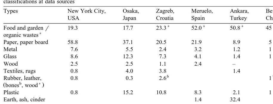
Table 1
Ž . Ž . Ž .
Composition percentage by weight of typical municipal solid wastes. Data taken from Sowers 1968 ; Yamamura 1983 ;
Ž . Ž . Ž .
Kovacic and Mayer 1995 ; Sanchez-Alciturri et al. 1995a and Wasti 1995 . The superscripts refer to original classifications at data sources
Types New York City, Osaka, Zagreb, Meruelo, Ankara, Beijing,
USA Japan Croatia Spain Turkey China
) ) )
Food and gardenr 19.3 17.7 23.3 52.0 50.8 45
)
organic wastes
Paper, paper board 58.8 37.1 20.5 21.9 8.9 5
Metal 7.6 5.5 2.4 3.2 1.2 1
Glass 8.6 12.3 7.3 4.1 1.4 1
Wood 2.5 2.5 1.1 2.4 –
Textiles, rugs 0.8 4.0 3.8 1.4
)
b
Rubber, leather, 0.8 0.3 2.6 1
b )
Žbones , wood .
Plastic 0.8 15.2 10.8 8.3 2.1 1
Earth, ash, cinder 1.4 32.4
Construction rubble 28.2 1.8
Others 6.7 46
influence on groundwater will be dominated by the amount of heavy metals and trace elements or the organic acid derivable from the solid waste. Many potentially hazardous materials find wide application in industry. For example,
poly-Ž .
chlorinated biphenyls PCBs have wide indus-trial usage due to their high dielectric constant, fire resistance and thermal stability; they come under various tradenames — for example ‘‘askarel oil’’ found in some old transformers. Some of the common industrial wastes are listed in Table 2. Many of these wastes ultimately find their resting places in landfill sites. Methylene
Ž .
chloride, trichloroethylene TCE , toluene and
m-xylene are among the hazardous organic
compounds most commonly found in landfill sites.
Since landfills are a complex mixture of an-thropogenic deposits, their physical properties would show a wide range of variation. For example, the density of urban refuse varies from 275 kgrm3 to 6400 kg
rm3 depending on the
amount of metal and construction debris it
con-Ž
tains e.g. Knight, 1990; Sharma et al., 1990;
.
Fang, 1995a; Sanchez-Alciturri et al., 1995b but in general, old landfills normally have low
Ž
density and seismic velocity Whiteley and
Jew-.
ell, 1992 . The published resistivity of solid waste and contaminated substrate range from
Ž
1.5 to ca. 20 Vm e.g. Knight et al., 1978; Laine et al., 1982; Everett et al., 1984;
Carpen-.
ter et al., 1991 with the associated leachate
Ž
being highly conductive Whiteley and Jewell,
.
1992 . The seismic P-wave velocity of urban refuse may range from 180 to over 700 mrs
Že.g. Knight et al., 1978; Calkin, 1989; Sharma
.
et al., 1990 depending on the degree of com-paction and state of saturation with the cover material having higher velocities than the
under-Ž
lying fill e.g. Calkin obtained a cover velocity of 320 mrs and refuse velocity of 180 mrs
.
over a municipal landfill near Chicago . Fortu-nately, these physical properties are often markedly different from those of the host geo-logical materials so that geophysical methods can be used for determining the volumetric distribution of fill.
2.4. Leachate formation and dispersal
composi-( )
M.A. MejurJournal of Applied Geophysics 44 2000 115–150
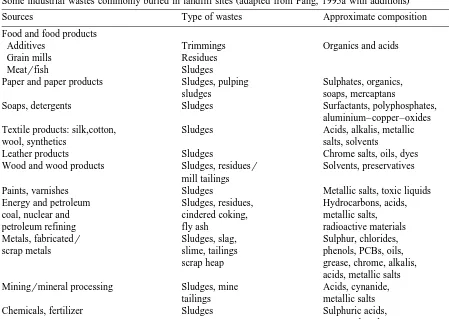
120 Table 2
Ž .
Some industrial wastes commonly buried in landfill sites adapted from Fang, 1995a with additions
Sources Type of wastes Approximate composition
Food and food products
Additives Trimmings Organics and acids
Grain mills Residues
Meatrfish Sludges
Paper and paper products Sludges, pulping Sulphates, organics,
sludges soaps, mercaptans
Soaps, detergents Sludges Surfactants, polyphosphates,
aluminium–copper–oxides Textile products: silk,cotton, Sludges Acids, alkalis, metallic
wool, synthetics salts, solvents
Leather products Sludges Chrome salts, oils, dyes
Wood and wood products Sludges, residuesr Solvents, preservatives mill tailings
Paints, varnishes Sludges Metallic salts, toxic liquids
Energy and petroleum Sludges, residues, Hydrocarbons, acids,
coal, nuclear and cindered coking, metallic salts,
petroleum refining fly ash radioactive materials
Metals, fabricatedr Sludges, slag, Sulphur, chlorides,
scrap metals slime, tailings phenols, PCBs, oils,
scrap heap grease, chrome, alkalis,
acids, metallic salts
Miningrmineral processing Sludges, mine Acids, cynanide,
tailings metallic salts
Chemicals, fertilizer Sludges Sulphuric acids,
organo-phosphates, copper sulphate, mercury arsenates
tion. Plausible biogeomorphic processes are summarised here and draws from observations and concepts in other geoscientific disciplines
Že.g. Schoell, 1980; Levinson, 1980; Perec, 1981; Robinson et al., 1982; Crawford and Smith, 1984; Jones, 1985; Bennet and Siegel, 1987; Palacky, 1987; Farquhar, 1989; Robinson, 1989; Yong et al., 1992; Bell and Jermy, 1995;
.
Fang, 1995a,b .
2.5. Mechanical decomposition
Urban waste deposit undergoes an initial short-term process of mechanical alteration due to loading and its bulk density and other physi-cal properties may change in response to this
Ž .
preliminary settlement process Fang, 1995a .
Ž
Other transient mechanical loads such as snow,
.
rainwater and surcharge loads will also con-tribute to the settlement process. Owing to the heterogeneous nature of the usually organic-rich urban waste, the distribution of settlement will
Ž .
be non-uniform Fang, 1995a and often leads to severe fracturing of the top seal of the landfill cover. The top seal is then highly vulnerable to erosion and infiltration of rainwater and snow-melts.
2.6. Physico-chemical and microbial weather-ing
The decomposition of landfilled wastes by
Ž
hydrolysis, hydration, carbonation, oxidation and
. Ž
solution and biological degradation mostly
mi-.
crobial processes cause the dissolution or dete-rioration of landfill materials, gas generation and production of leachate. Landfill sites pro-vide ideal environments for bacterial colonies to
Ž
grow since nutrients availability, and substrate composition and temperature requirements are
.
met and most bacteria flourish in the aerobic
Ž
condition above the groundwater table e.g.
.
Fang, 1995b . Initially, the microbial degrada-tion of landfill materials occurs under aerobic conditions. As the oxygen becomes depleted by the microbial activity, anaerobic conditions rapidly set in and the biodegradation of organic materials becomes anaerobic. Methane gas is generated bacterially from the abundant organic materials under the prevailing anaerobic condi-tions.
Although it is now widely required in
land-Ž
filling that refuse be dynamically compacted to
.
minimise volume and then covered by a thin
Ž
layer of soil or clayey seal to minimize wind
.
dispersion at the end of each operative day, rainwater ingress commonly takes place in wet seasons during landfilling and for capped sites, through cracks in the cover and along contact points between fill and host material. Infiltrating rainwater, groundwater, or other liquids dis-posed of within the wastes will dissolve some soluble mineral constituents of the landfill once the absorbent or field capacity of the fill is exceeded and free drainage of water can occur. This leaching process may remove the common mineral elements such as calcium, magnesium, potasium, nitrogen and phosporous or remove
Ž .
the bonding materials e.g. clay resulting in changes in matrix cement or the ion concentra-tion within the landfill-porewater system and consequently causing significant physical prop-erty changes. The ion exchange reaction, speeded up by bacterial activity, also causes changes to the structure and composition of the
Ž
landfill–porewater system. For example, hy-drogen sulphide may be converted to sulphuric acid, methane gas may become converted to
carbon dioxide and water by microbial metabolism while the carbon dioxide by-product
.
may combine with water to form carbonic acid .
Ž .
The resulting liquid termed leachate is rich in fungi, bacteria, inorganic salts and organic mat-ter; but the compositional trend may be water and dissolved inorganic salts, water and dis-solved organic wastes and organic fluids, or simply organic acids depending on the availabil-ity of solvent and solute types in the leached mass.
In terms of availability of solute types, the bottom ash residues from urban solid waste incinerators contain considerable amounts of
Ž
leachable heavy metals lead, zinc, cadmium,
. Ž
copper, and chromium and salts Bahout et al.,
.
1995 , and this will be reflected in the composi-tion of leachate derived from such deposits. If pyrite is available in wastes containing mine tailings, it may be oxidised to sulphuric acid while the decomposition of vegetation may pro-duce organic acids. PCBs have low solubility in water, and if present in the landfilled wastes, we can expect low concentrations of PCBs in the leachate dissolved phase, but they are more likely to occur in solid organic matter or in the oil fraction.
Since higher volumes of water would have passed through poorly compacted waste materi-als in old landfill sites compared to modern compacted landfills, there should be relatively lower concentrations of chemical constituents in leachates derived from old landfills with
effi-Ž .
cient migration processes Radnoff et al., 1992 . Note that for poorly consolidated or uncom-pacted wastes at shallow burial depths, and with inadequate capping, the absorbent or field ca-pacity may be achieved within only a few years following initial waste emplacement, thus al-lowing early generation of leachate. For well compacted and deeply buried wastes with low permeability capping, the field capacity may not be achieved until after several years, but the waste compression process may facilitate early formation and expulsion of leachate from the
Ž
( )
M.A. MejurJournal of Applied Geophysics 44 2000 115–150
122
.
et al., 1997 . Note also that the decomposition of organic and inorganic solids will be
associ-Ž
ated with a fill volume change causing
shrink-.
age or swelling .
In general, the pore fluids produced from landfill are mostly acidic, but will vary in
com-Ž .
position from country to country Table 3 , community to community and with season. Bac-teriogenic methane is formed by fermentation of organic material in conditions of depleted oxy-gen supply, and for a given leachate, a number of chemical changes occur as it evolves from
Ž .
the aerobic acetogenic stage to the anaerobic
Žmethanogenic stage Robinson, 1989 ; the to-. Ž .
Ž .
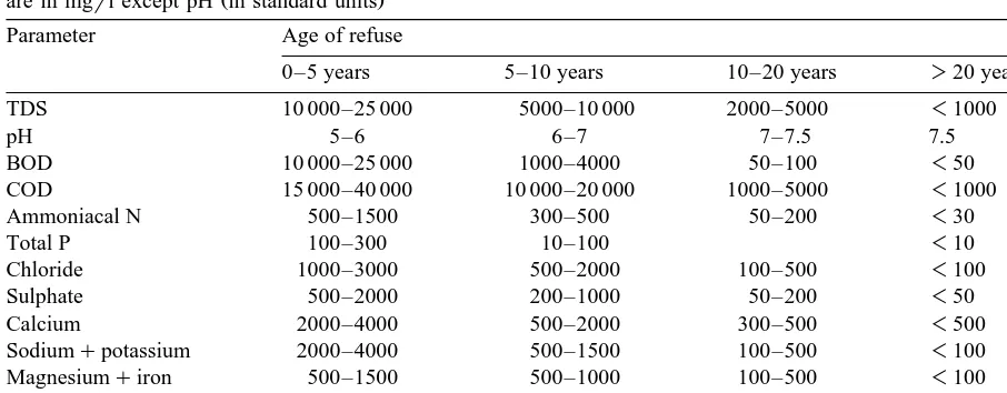
tal organic content TOC , total free fatty acids content or acetone content and TDS are high during acetogenesis and low during methano-genesis. That is, the composition of the leachate will change as the refuse in the landfill ages
ŽFarquhar, 1989 . In general, the leachate from.
a young landfill may be characterised by high levels of organic acids, ammonia and TDS, but as much of the biodegradable mass is broken down with time, the concentrations of these parameters will decrease in the leachate
pro-Ž .
duced from the ageing landfill see Table 4 . The leachate may contain toxic or hazardous substances in solid or gaseous forms and might show up as high concentrations of chloride, iron and zinc ions. Those elements with high ionic mobility generally have the highest concentra-tion whilst those having low mobility usually have the lowest concentration in leachates
ŽBagchi, 1987 . The pH tends to increase with. Ž
time i.e., from an initial acidic state to a neutral
.
state while the biological and chemical oxygen
Ž . Ž
demands BODrCOD decrease with age see
.
Table 4 . The concentration of organic carbon
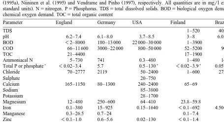
Table 3
Ž . Ž .
Regional variations in leachate composition. Data for columns 2–6 are from Robinson et al. 1982 , Ehrig 1983 , Fang
Ž1995a , Niininen et al. 1995 and Vendrame and Pinho 1997 , respectively. All quantities are in mgrl except pH in. Ž . Ž . Ž .
standard units . Nsnitrogen. PsPhosphorus. TDSstotal dissolved solids. BODsbiological oxygen demand. CODs chemical oxygen demand. TOCstotal organic content
Parameter England Germany USA Finland Brazil
TDS 1–520 402–6794
pH 6.2–7.4 6.1–8.0 3.7–8.5 3–8 6.05–7.51
BOD -2–8000 180–13 000 22 000–30 000 1–3900
COD 66–11 600 3000–22 000 800–50 000 52–5200 90–2000
TOC 21–4400 17–1900
Ammoniacal N 5–730 741 0.3–480 1–480 14–1080
) ) )
Total P or phosphate -0.02–3.4 5.7 0.5–130 -0.02–3.9 0.057–2.312
Chloride 70–2777 2119 50–2400 1–600 275–1949
Sulphate 20–750
Calcium 165–1150 80–1300 240–2400 65–69
Sodium 85–3800
Potassium 28–1700
Magnesium 12–480 250–600 64–410 23.8–59.8
Iron 0.1–380 15–925 0.15–1640 -0.1–692 4.504–9.9
Manganese 0.3–26.5 0.7–24 0.1–7.4
Zinc -0.1–1.0 0.6–5.6 0.02–130 -0.1–1.4
Cadmium -0.005–0.01 0.0052 -0.0001–0.0047 0–0.033
Chromium -0.05–0.16 0.275 -0.001–0.134 0.005–0.056
Nickel 0.05–0.16 0.166 0.15–0.9 -0.003–0.394 0–0.333
Lead 0.05–0.22 0.087 -0.001–0.042 0.021–0.7
Table 4
Ž .
Typical changes in leachate concentrations with age of refuse after Farquhar, 1989; Birks and Eyles, 1997 . All quantities
Ž .
are in mgrl except pH in standard units
Parameter Age of refuse
0–5 years 5–10 years 10–20 years )20 years
TDS 10 000–25 000 5000–10 000 2000–5000 -1000
pH 5–6 6–7 7–7.5 7.5
BOD 10 000–25 000 1000–4000 50–100 -50
COD 15 000–40 000 10 000–20 000 1000–5000 -1000
Ammoniacal N 500–1500 300–500 50–200 -30
Total P 100–300 10–100 -10
Chloride 1000–3000 500–2000 100–500 -100
Sulphate 500–2000 200–1000 50–200 -50
Calcium 2000–4000 500–2000 300–500 -500
Sodiumqpotassium 2000–4000 500–1500 100–500 -100
Magnesiumqiron 500–1500 500–1000 100–500 -100
Zincqaluminium 100–200 50–100 10–50 -10
Alkalinity 10 000–15 000 1000–6000 500–2000 -500
often exceeds 8000 mgrl in the leachates from young landfills and 465 mgrl in leachates from
Ž .
old landfills Dearlove, 1995 .
The composition of the leachate will depend on the type and age of fill, water infiltration rate
Ž .
and pH Farquhar, 1989 but the rate and quan-tity of leachate and landfill gas production will be affected by the depth of burial of fill, re-gional climatic conditions, variations in water table, the landfill capping practice and fluid inflow and outflow controls at the site. It can be
Ž
expected that surface layers of refuse i.e.,
shal-.
low burial depth may experience rapid aerobic decomposition whilst the bulk of the waste at depth may have only been partially decomposed under anaerobic conditions thus leading to dif-ferent physical properties. Also, landfill degra-dation will be quicker in humid tropical regions than in cold regions and for identical fill com-position and water influx–efflux conditions, the leachate from the warmer climate will have a higher concentration of dissolved materials rela-tive to the background groundwater composition
Žin analogy to variation in saprolite composition
Ž ..
in chemically weathered rocks Palacky, 1987 as also suggested by the data presented in Table 5. If precipitation is the main source of water
for leachate generation in the fill, then it can be expected that storms will have a role in leachate discharge.
The transport of leachate through the landfill is slow, unsteady, non-uniform and sometimes
Ž .
discontinuous Fang, 1995a depending on the degree of compaction of the fill and seasonal changes in water supply to the system. Within the landfill, this liquid may collect in various
Ž .
areas e.g. perched saturated zones or mound at the bottom of the landfill. This leachate starts seeping as soon as enough hydrostatic head is developed. Biochemically controlled exothermic reactions are known to cause higher
groundwa-Ž
ter temperatures in leachate MacFarlane et al.,
.
1983 and because of the ingress of leachate from the upper leached zones, the temperature in the lower portion of the landfill is often significantly higher than elsewhere in the
Ž .
leached section Fang, 1995a . Consequently, there are higher bacterial activities and higher ion exchange reactions in the lower parts of the landfill as time progresses. These microbial– chemical decomposition reactions may cause significant changes to the existing pore fluids
Žand to the substrate if the fill is in direct
.
()
M.A.
Meju
r
Journal
of
Applied
Geophysics
44
2000
115
–
150
124
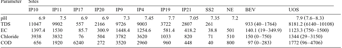
Table 5
Ž .
Comparison of some leachate components at four sites in different geographic regions. Data for the Durban sites IP10-SS2 South Africa are from Bell and Jermy
Ž1995 ; SS2 is a surface stream sample and the rest are from inspection pits IP . Data for site NE northern England are from Kalteziotis et al. 1995 . Data for. Ž . Ž . Ž .
Ž . Ž . Ž . Ž . Ž .
Beverly BEV and Upper Ottawa Street UOS landfill sites Canada are from Birks and Eyles 1997 . Electrical conductivity EC is in mSrm and except for
Ž .
pH, the rest are in mgrl. In the last two columns, the average values of the parameters as well as their respective ranges in parenthesis are given Parameter Sites
IP10 IP11 IP17 IP20 IP9 IP4 IP19 IP21 SS2 NE BEV UOS
Ž .
pH 6.9 7.5 6.9 6.9 7.3 7.45 7.7 7.05 7.35 7.2 7.9 7.6–8.3
Ž . Ž .
TDS 11047 9902 557 2166 9726 9003 3722 2807 261 933 40–1764 8181.2 6140–10108
Ž . Ž .
EC 1397.4 1530 85.7 300.9 1448.4 1254.6 581.4 418.2 38.8 501 140.1 19–349.9 1123.3 750–1500
Ž . Ž .
Chloride 3938 3832 76 504 3782 3620 1033 820 71 510 150 0–750 1344 29–3150
Ž . Ž .
On passing through the base of the landfill, the metal ions in solution may be removed from the aqueous phase by ion exchange, sorption or
Ž
precipitation onto the substrate especially if
.
clayey . However, organic carbon in colloidal form in the leachate often has higher cation exchange capacity than clay and can sorb high
Ž
concentrations of metal ions from solution as can some inorganic colloids which form under
.
certain chemical conditions . The metal ions sorbed preferentially onto the surface of col-loidal particles may thus by-pass the natural attenuation processses as the leachate seeps into
Ž .
the substrate Dearlove, 1995 . Within the sub-strate, it mixes with groundwater forming a leachate plume.
Initially, on entering the anaerobic groundwa-ter system, the organic magroundwa-terial in the leachate is slowly biodegraded forming more acids which
Ž
may react with aquifer materials cf. Bennett
.
and Siegel, 1987 with attendant changes in the fluid chemistry near the water table. In this deoxygenated environment, inorganic materials
Ž .
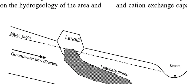
in the leachate e.g. iron, manganese may be dissolved in the groundwater. The dispersing leachate extends laterally and vertically as it sinks towards the bottom of the substrate form-ing a 3-D contaminant plume that may be steeply
Ž .
dipping see Fig. 2 . The amount of groundwa-ter contamination resulting from this invasion will depend on the hydrogeology of the area and
the attenuation capacity of the substrate. It may be effectively diluted and dispersed by ground-water in highly permeable geological formations with high flow rates. Given enough time in less permeable formations, or with slowly moving
Ž
groundwater, the plume laden with inorganic
.
salts may enhance mineralisation of groundwa-ter. Since it is a moving and continuously evolv-ing 3-D feature, it will in time be dispersed over a sizeable area, possibly with distinct composi-tional zonations.
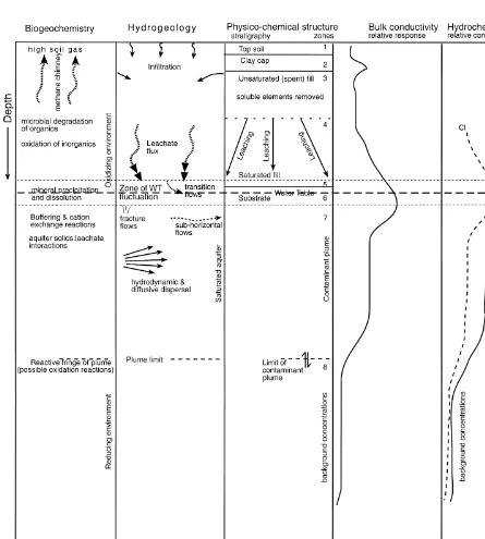
2.7. Conceptual resistiÕity model
A conceptual resistivity model can be devel-oped in line with the above biogeomorphic and hydrochemical considerations, since the observ-able geoelectrical response of landfill sites and environs will vary in relation to significant changes in the chemistry of subsurface pore fluids. It can be expected that surface layers of refuse may experience rapid aerobic decomposi-tion whilst the bulk of the waste at depth may have only been partially decomposed under anaerobic conditions, thus leading to different physical properties. For a leachate-generating landfill in contact with granular substrate, the interactions between the invading leachate and substrate material may cause geochemical alter-ations of substrate depending on its buffering and cation exchange capacities.
( )
M.A. MejurJournal of Applied Geophysics 44 2000 115–150
126
Accordingly, several zones are recognised in the generalised conceptual model shown in Fig.
Ž .
3. The top soil and clay cap i.e., zones 1 and 2 form the uppermost confining layers. The resis-tivity of the top soil will vary from region to
region and with season but the usually 0.3 to 1 m thick clay cap will in general be relatively conductive. Landfill sites are notorious for high
Ž
levels of soil gas principally methane and
car-.
bon dioxide . Fractured clay caps would also
Fig. 3. A conceptual resistivity model for old landfill sites with leachate generation and migration into groundwater system
Ž .
allow gas migration. The geoelectrical signa-tures of zones 1 and 2 will be affected by seasonal changes. In wet seasons, infiltrating water may drive out gas thus lowering its bulk resistivity. Conversely, rising vapours in the dry periods will drive out soil moisture with atten-dant increase in bulk resistivity. The degree to which these changes are detectable will depend on the nature of the materials in zones 1 and 2. For instance, the influx of gas into pore spaces in some clays may cause appreciable resistivity
Ž .
increases if water or leachate is displaced but not so for a highly resistive dry sandy topmost layer. If these cover materials are iron-rich, it is conceivable that the rising methane and sulphur dioxide in landfills may lead to the formation of a pyritic geochemical alteration halo akin to the so-called ‘sulphide chimney’ over fractured hy-drocarbon accumulations overlain by iron-rich
Ž
sediments or redbeds e.g. Oehler and
Stern-.
berg, 1982,1984; Ostrander et al., 1983 which might be detectable in 3-D or time-lapse geo-electrical surveys.
The clay cap is underlain by a zone of perva-sive leaching of refuse and residual products
Ži.e., zone 3 in Fig. 3 . This is the top part of the.
landfill waste where oxygen and bacterial
sup-Ž
ply is abundant and will thus decompose
.
quicker than the deeper parts . The bulk resistiv-ity of this oxidized zone will show a relative
Ž
increase with time as the organics for microbial degradation become depleted in supply, oxida-tion of inorganics tends towards compleoxida-tion and much of the soluble elements have been
re-.
moved . The leaching of clay minerals from the original landfill-soil mixture would leave behind the non-degradable fill material and siliceous geomaterial with average soilrrock grains of
Ž .
larger size fraction cf. Witmer et al., 1984 and of relatively higher resistivity than the parent landfill material. It may thus be relatively resis-tive in comparison with the clay cap and the underlying zone of incomplete refuse
decompo-Ž .
sition i.e., zone 4 . However, the rate of water flux through zone 3 will affect its eventual resistivity characteristics — it will be more
resistive for fast flows in comparison to slow fluxes that will cause lower resistivities.
Zone 4 occurs in the lower part of the waste deposit and is dominated by relatively immature leaching and will exhibit relatively low bulk resistivities. For landfill resting on highly im-permeable substrate, leachate mounding may occur in the basal part of the waste deposits rendering it the most electrically conductive part of the entire landfilled section. However, if the landfill rests directly on a relatively permeable substrate saturated with groundwater, fluctua-tions in the water table may occur within a section encompassing the basal part of the
land-Ž .
fill zone 5 and the uppermost part of the
Ž .
substrate zone 6 as schematised in Fig. 3. The mineral salts and organic material leached from the fill materials will be deposited near the water table depending on the local
hydrogeolog-Ž
ical and Eh–pH conditions in analogy with the well-known process of supergene enrichment of
Ž .
metallic sulphide minerals Levinson, 1980 and
.
chemical weathering of soilsrrocks causing an
Ž
increase in TDS and therefore electrical
con-.
ductivity and other chemical parameters in the
Ž .
porewater cf. Knight et al., 1978, Fig. 8 . Due to water table fluctuations, the zone of deposi-tion or mineral enrichment may extend from the basal part of the landfill into the upper part of the subjacent geological formation or may lie well beneath the base of the landfill depending on the permeability, fluid saturation, groundwa-ter flow and dispersion characgroundwa-teristics of the substrate and the mobilities of the ions in solu-tion. Below the water table, the leachate mixes with groundwater and reacts with substrate
ma-Ž .
terial cf. Bennet and Seigel, 1987 forming a
Ž .
relatively conductive plume zone 7 . Beyond
Ž .
the plume, the uninvaded substrate zone 8 will have TDS and conductivity parameter values
Ž
intrinsic to the natural medium i.e., background
.
concentrations .
( )
M.A. MejurJournal of Applied Geophysics 44 2000 115–150
128
be expected that this zone will have a dis-cernible conductivity signature on geoelectrical soundings in leachate-bearing landfill environ-ments. For unsaturated substrate in contact with leachate-generating landfill deposits, the leachate will advance with the infiltrating water and displace the air or residual connate water in the pores spaces of the substrate. This displace-ment will cause a decrease in the resistivity of sandy or carbonate formations but the effects may not be geoelectrically appreciable in some clayey substrate. If the unsaturated section were thick enough, the rate of advance of the leachate
Ž
front and hence the depth location of the zone
.
of maximum leachate concentration will de-pend on the buffering and cation exchange ca-pacities of the substrate. For instance, calcite-rich sands may attenuate the leachate better than
Ž .
dominantly siliceous sands e.g. DoE, 1996 with consequent differences in the position of occurrence of leachate-related geoelectrical con-ductors in unsaturated substrates.
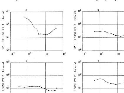
In Fig. 4 are shown the typical landfill sound-ing curves from various geological, climatic and geoenvironmental settings. Note that all the curves are of the minimum or H-type. The most conductive segment of each sounding curve cor-responds to the saturated basal section of the respective landfill andror leachate-invaded sub-strate. Note, however, that an apparently highly resistive terminal segment of a sounding curve
Ž
at a landfill site as exhibited by the curves
.
shown in these figures may not always be indicative of a resistive nature for the substrate but rather may be due to 3D distorting influ-ences of the typically complex site geometry
Ž . Ž
Fig. 4. Typical resistivity sounding curves from landfill sites in different geographical regions. a Australia Knight et al.,
. Ž . Ž . Ž . Ž . Ž . Ž .
especially when the expanding electrodes oc-cupy positions outside the actual confines of the landfill site.
2.8. Relationship between geoelectrically impor-tant hydrochemical parameters
Electrical conductivity is usually taken as a measure of the total dissolved salts in ground-water by hydrogeochemists whereas chloride content is used as a conservative leachate indi-cator parameter in water sample studies since, apart from dilution, it undergoes very little chemical or biological change in the
groundwa-Ž .
ter system Baedecker and Apgar, 1984 . Some chemical analyses of groundwater contaminated by leachate seeping from a landfill site that
Ž
closed in 1989 in Durban, South Africa Bell
. Ž
and Jermy, 1995 are shown in Table 5. The data were presented at the GREEN ’93 confer-ence in June 1993 and were probably collected
.
in 1992 . Also shown in this table are the chemical parameters for leachate from a
6-year-Ž
old landfill in northern England Kalteziotis et
.
al., 1995 and for the leachates from the Beverly
Ž .
landfill active from 1965–1980 and Upper
Ž .
Ottawa Street landfill active from 1950–1980
Ž
near Hamilton in Ontario, Canada Birks and
.
Eyles, 1997 . For the Canadian examples, the
Žaverage, minimum and maximum values of.
the respective parameters for the monitoring period 1980–1994 are presented. The levels of TDS and conductivity for the leachate-impacted groundwater from downgradient measurements in the vicinity of the Durban landfill are higher than those recorded within the younger landfill site in the UK and comparable to those for the Canadian sites. Since even higher values may be obtained for leachate samples from the
Dur-Ž
ban landfill than those presented here possibly
.
diluted offsite samples , the data in Table 5 could be interpreted as supporting the earlier contention that apart from age, climatic differ-ences might lead to variations in the amount of soluble material removed from a given landfill material in different geographical locations.
The spatial variation of plume properties is of geoexploration interest and will be examined here using the data for Durban landfill. The Durban landfill sampling points were distributed over a grid across the southeastern border of the
Ž
landfill where seepage was occurring see Bell
.
and Jermy, 1995, Fig. 3 . Sampling stations IP9, IP4, IP19 and IP21 in Table 5 were located along the axis of the plume at increasing dis-tances from the southeastern border of the
Dur-Ž
ban landfill the typical inspection pit spacing
.
was about 35 m . For these stations, note the decrease in TDS and electrical conductivity with increasing distance from the landfill. To illus-trate the relationship between groundwater
con-Ž .
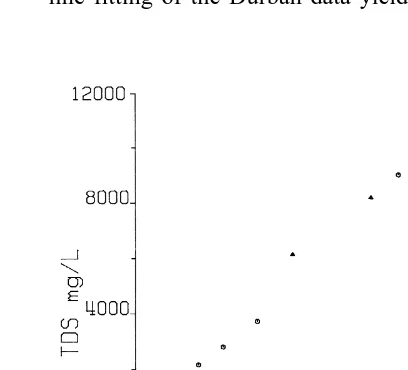
ductivity and TDS and chloride content in the plume emanating from the Durban landfill, the data from all the sampling stations in Table 5 are shown graphically in Figs. 5 and 6. Note the almost linear relationship between conductivity and TDS in Fig. 5 and between conductivity and chloride content in Fig. 6. Simple straight-line fitting of the Durban data yielded the
rela-Fig. 5. Relationship between fluid conductivity and TDS. The round symbols represent the data from Durban landfill
Ž .
in South Africa Bell and Jermy, 1995 . The data from Beverley and Upper Ottawa Street landfill sites in
Hamil-Ž .
ton, Canada Birks and Eyles, 1997 are shown by
triangu-Ž .
( )
M.A. MejurJournal of Applied Geophysics 44 2000 115–150
130
Fig. 6. Relationship between conductivity and chloride content for two landfill sites. The data from the Durban site are shown by circular symbols while the triangular symbols represent the data from Morley landfill site in
Ž .
Australia Buselli et al., 1990 .
tionships TDSs y54.4q7.04sw and Cls y257.2q2.83sw, where the electrical
conduc-Ž .
tivity of the groundwater sw is in mSrm and the other two parameters are in mgrl. However, it is often preferable to consider the
relation-Ž
ships between the logarithms of these data cf.
.
Table 6 . The resulting relationships for the same data sets are
log TDSs0.8q1.015 logsw
Some published data for the Beverly and Upper Ottawa Street landfills in Hamilton in
Ž .
Canada Birks and Eyles, 1997 and Morley
Ž .
landfill site in Australia Buselli et al., 1990 are also presented in Figs. 5 and 6 for comparison with the Durban data. The fluid conductivity and chloride content data from Morley landfill
Ž
show the same trend as the Durban data see
.
Fig. 6 . Although not an ideal data set, the published average, minimum and maximum conductivity and TDS values for the two landfill
Ž .
sites in Hamilton Birks and Eyles, 1997 are
Ž .
also in accord with the Durban see Fig. 5 . It is
Ž .
interesting as shown in Fig. 5 and Table 6 that a similar linear trend exists in data from a non-landfill environment — a hydrogeochemi-cally zoned regional aquifer with high back-ground inorganic salts near the city of Picos in
Ž .
northeast Brazil Meju et al., 1997 , which could suggest that the leachates from the selected landfill sites derive their conductive nature largely from inorganic salts.
It might be expected that if similar relation-ships exist between bulk resistivity and TDS, then it will be possible to predict compositional trends in hydrochemical parameters such as TDS and chloride content from surface geoelectrical
Ž .
soundings e.g. Buselli et al., 1990 . No such relations have been found as yet for routine geoelectrical use. However, from a dc resistivity study of acid-mine drainage problem, Ebraheem
Ž .
et al. 1990 obtained the relation,
logsbs y0.333q0.6453 log TDS
Ž
.
=
Ž
ors s0.4645 TDS0.6453.
Ž .
3 bwhile a appraisal, by this author, of the re-sults of a TEM–AMT study of part of a highly saline, relatively homogeneous, sandstone
Table 6
Summary statistics for regression analysis of fluid conductivity vs. TDS in some groundwater systems. In columns 2 to 4, the top set of numbers relates to logarithmic fitting while the numbers in brackets are for non-logarithmic fitting. The data
Ž .
used were from various sources Bell and Jermy, 1995; Birks and Eyles, 1997; Meju et al., 1997
Ž .
Regression parameter Durban, S. Africa Picos, NE Brazil Combined set inc. Canada
Ž . Ž . Ž .
Intercept 0.8"0.05 y54.4"341 1.1"0.17 81.6"60.9 0.8"0.09 7.69"88
Ž . Ž . Ž .
Ž .
aquifer Meju et al., 1997 suggested the rela-tion
logsbs y0.3215q0.7093 log TDS
Ž
.
=
Ž
orsbs0.477 TDS0.7093.
Ž .
4where sb is the bulk conductivity of the forma-tion in mSrm and the TDS is in mgrl.
For the sake of completeness, we may
tenta-Ž Ž .
tively adopt the above relations Eqs. 3 and
Ž ..4 in the present discussions but note that they were determined for relatively homogeneous materials and thus, may not hold in the typical landfill environment where significant quantities of conductive metal and clay may be present. Moreover, even under favourable conditions,
Ž .
the two constants intercept and slope in the
Ž . Ž .
above Eqs. 3 and 4 may have to be evaluated for different landfill environments to enable a working relation between the bulk conductivity of the contaminated homogeneous substrate, or saturated basal fill and the fluid conductivity, to be determined in conjuction with variants of the other relations given above. Assuming that Eq.
Ž .4 is applicable to landfill environments,
com-Ž . Ž .
bining Eqs. 1 and 4 leads to
logsbs0.2452q0.7196 logsw
= ors s1.7587s0.7196
5
Ž .
Ž
b w.
relating fluid and saturated fill conductivities. An alternative approach may be sought based
Ž .
on the popular Archie’s 1942 law, sbs
ks fm, where f is porosity, m is the
cementa-w
tion factor and k is a constant. Along this line,
Ž .
Yaramanci 1994 developed a relation between in situ resistivity and water content in salt rocks; a simplification of the formula yields the work-ing relation
s ss Wm
Ž .
6b w
with Wm as the water content and m(1.6–1.9.
Ž
This would suggest that under ideal i.e.,
clay-.
free conditions, we may directly estimate the proportion of contaminated water in an invaded homogeneous geomatrix of known bulk and
Ž .
fluid conductivities. It is stressed that Eq. 6 is
adopted here only for illustration purposes-the
Ž
reader is referred to Worthington 1993 and
.
references therein for sophisticated adaptations of Archie’s law.
2.9. Conceptual prediction of hydrochemical parameters and age of saturated fill
The chemical parameters and age of fill are important components of any genetic recon-struction scheme. Variations in fill compositions of different ages have been noted by several
Ž .
workers see, e.g. Knight et al., 1978 . How-ever, from a geoelectrical viewpoint, an exciting development in geochemical characterisation of landfill leachates is the observation that these
Ž
variations are consistent with age e.g.
Far-.
quhar, 1989; DoE, 1996 as can be gleaned from Table 4. If the approximate concentrations of the relevant hydrochemical parameters can be predicted by virtue of the emprical relationships developed in the previous section, it follows that one can, at least at a conceptual level, predict the age range of a given saturated fill using the information furnished by surface andror borehole geoelectrical measurements. The main problem that will bedevil such an approach is the fact that there are three main sources that contribute to the observed leachate composition — infiltrating groundwater or rain, waste deposits and ambient geological materi-als. Section 3 will focus on the effective integra-tion of the above concepts and models in rou-tine geoelectrical investigations.
3. Development of a consistent investigative geoelectrical approach
In line with the above developments, we may propose a four-phase diagnosis approach for landfill investigations. The analysis of historical
Ž
documents town development plans and
topo-.
( )
M.A. MejurJournal of Applied Geophysics 44 2000 115–150
132
the first phase in site investigation since this can furnish much of the necessary information to address some important practical issues to be discussed below. The second phase will be to define the site constraints and boundary
condi-Ž
tions natural and gradational or anthropogenic
.
and abrupt and thence a site-specific explo-ration model that is consistent with geotechni-cal, biologigeotechni-cal, geological and physico-chemical considerations. Site-specific model development involves posing the problem with the attendant constraints in a form that can be addressed using the chosen geoelectrical methods. In gen-eral, the main elements of a closed landfill site
Ž
are the site boundaries which are typically
.
irregular , buried near-vertical rock faces in dis-used hard-rock quarries, dome-shaped or tabular cap, depth locations and dips of the layers of refuse and sealing materials, the integrity of the sealing zones, the position of access roads or buried bund walls, and the presence of high
Ž
levels of hazardous gases, leachate or corrosive chemicals in the case of industrial waste
dis-.
posal sites or perched groundwater bodies. The third phase is to design and execute a geophysical survey to define the model parame-ters. The geophysical methods should be se-lected to define the various parts of the above model and with data quality and integrity as key considerations. Obviously, the various methods would respond differently to specific aspects of this model and would suggest that an integrated approach is the best option, barring financial constraints. In designing and executing surveys to investigate covered landfill sites, it may be necessary to combine geoelectrical measure-ments with some other geophysical technique
Žsuch as seismic refraction but electrical and.
EM methods must be seen as a necessary com-bination. The final phase will be the provision of an appropriate physico-chemical solution to the given problem, based on site-constrained
Ž
analysis of the geophysical field data and for added value, the definition of future monitoring
.
requirements . Some of the above issues are explored in more detail in what follows and it
will be conveniently assumed that we are deal-ing with electrical and EM investigative tools.
3.1. Practical considerations in surÕey design
and implementation
3.1.1. Desk study: problem definition and site description
Some pre-survey considerations that have been found from experience to be very useful are listed in Table 7. Analysis of problematical observations and detailed site description consti-tute the desk study. It is important that the perceived or identified geoenvironmental prob-lem is well posed taking into account all the available information. It is even more important to have a clear definition of what form of solution is expected since the investigative strat-egy will vary depending on whether the survey goal will be served merely by a non-committal reporting or require suggestions andror recom-mendations for partial or full implementation. For example, the presence of leachate poses the threat of groundwater contamination and it is important to design the geophysical survey to map the leachate and any possibly linked aquif-erous materials at the site. The site dimensions and current usage will influence the choice of field methods since some techniques would re-quire more space for depth probing than others while some other ones may be sensitive to metallic constructions or other obstructions within the site, say. Also, a change in land use such as the introduction of domestic or indus-trial infrastructure at the site may have disturbed
Ž
the ground creating potential pathways for
pol-.
lutant migration .
It is important to know whether the landfill site originally served as a quarry, in which case we may expect irregular boundaries or whether it was specially constructed with regular borders for waste containment. At disused quarry sites, it is also not uncommon to have several other minor excavations in the vicinity of the main excavation and any interconnections between
Ž .
Table 7
Ranked practical considerations for a consistent investigative approach. Ranks 1 to 11 provide problem definition and detailed site description. Ranks 12–13 relate to geoelectrical field study while ranks 14–15 relate to problem solution and environmental diagnostics
Practical considera- Model features and enviro-economic Effect on electrical surveying and
diag-tions constraints nosis
1 Environmental prob - Identified hazardous gases and leachate Detailed solution required for remedia-lem and demanded so- or perceived threat to environment tion and monitoring; non-comittal
re-lution porting may involve less detailed
sur-veys
2 Site dimensions and Landfill sites vary in size and shape. Methods appropriate to site geometry current usage Reclaimed site may contain domestic, and existing constructs are to be se-recreational, agricultural or light indus- lected. Change in land use or cover trial infrastructure with new cover over material may limit model resolution disturbed parts.
3 Type of initial excava- Site may be a disused quarry with Nature of borders controls gross struc-tion steep or sloping irregular borders or tural dimensionality; multiple
excava-purpose-built structure with regular tions will require dense sampling. borders. Multiple excavations or cells
may be present and linked.
4 Type and state of basal Basal liner, if present, may be thin Basal clay liner and active drainage lining and drainage compacted clay-till layer or zone of system may have comparable resistiv-system graded granular substrate. Basal ity to saturated fill. Focused 3D depth drainage to sumps common probes and specialized data processing required for assessment of liner in-tegrity.
5 Fill type, tipping his- Fill may be of domestic, industrial or Well-compacted and homogeneous fill tory and burial pattern co-disposal type and roughly homoge- may be approximately 1D; separating noeus with compaction layering or walls, steeply-sloping cover and com-strongly heterogeneous with separating plex site borders impart 2Dr3D
signa-Žbund walls. tures
Ž .
6 Age of fill and burial Field absorbent capacity of fill may Fill resistivity structure will be con-depth be attained with time and burial depth trolled by fill stability and form of with consequent leachate production; occurrence of leachate. Fill resistivity fill stabilization with leaching and age will vary with age and requires
peri-odic monitoring
7 Topography, differen- Fracturing of landfill cover caused by Anisotropy and topographic distortions tial subsidence and subsidence. Linear fracture systems are to be expected. Azimuthal or 3D landfill cover integrity may follow decompaction trends; al- surveys required to maprmonitor dis-low erosion and thinning of cover, turbed cover. Sounding parallel to frac-infiltration of surface water, and escape ture group trend for approximate 1D
of landfill gas inversion
8 Climatic environment Rate of fill leaching and leachate gen- Conductivity of leachate from fill of eration dependent on infiltration and given composition will vary with
cli-climate matic region
( )
M.A. MejurJournal of Applied Geophysics 44 2000 115–150
134
Ž .
Table 7 continued
Practical considera- Model features and enviro-economic Effect on electrical surveying and
diag-tions constraints nosis
methane gas depends on nature of host of maximum concentration of leachate
rock in unsaturated aquifers.
10 Geochemical alter - Seepage of methane gas may lead to 3D surveys required to map
geochemi-Ž
ation halo alteration of surficial materials e.g. cal alteration haloes or mineralisation pyrite formation in iron-rich sedi- chimney. IP method best for detecting
.
ments ; leachate migration may cause zones of pyritic alteration. mineralization of groundwater
11 Physical property con- Electrical properties of fill and sub- Lack of contrast limits model resolu-trasts and background strate may be similar, or seeping tion. High background noise reduce noise leachate may overprint signatures from data accuracy and demands improved
Ž
fill-substrate contact. Urban sites are signal detection capability highly
sen-.
typically noisy sitivity equipment needed .
12 Budgetary constraints Limits the range of field measurements
and reporting time and the level of sophistication of
inter-pretation
13 Applicable geophysi- Site condition, expected contrasts,
sub-cal methods and sam- surface structural complexity and
fi-pling frequency nancial constraints influence choice of
tools. Pilot study will aid selection of techniques with optimum potential for target definition. Sampling frequency affects resolution of anomalies 14 Quantitative data inter- Data may be corrupted by cultural Data quality assurancercontrol
pro-pretation requirements noise. There may be insufficient con- gram must be implemented. 1Dr2D trasts between fill and host. Leachate inversion may suffice for layered fill; plumes may have gradational bound- 3D modelling needed for complex
aries. structures. Smooth models appropriate
for leachate plume, low-contrast sys-tems or noisy data
15 Model-based hazard Leachate contamination of groundwa- Characterisation of subsurface hazards identification and anal- ter; accumulation of methane gas poses or pollution potential rests on capabil-ysis fire and explosion hazards ity to map geology and emitted fluids
ascertained as they may serve as possible migra-tion paths for the fluids expelled during the backfilling operations. The presence or absence of a basal lining must be ascertained and has implications for the pollution potential of a landfill site. The landfill may rest directly on a
Ž
natural liner e.g. clayey formation or graded
.
coarser-grained granular substrate or on
syn-Ž
thetic geomembranes as in modern waste
con-.
tainment facilities .
It is useful to know what method of tipping was used, what type of waste was buried, how it was distributed at the site, and whether the
shape of excavation has remained unchanged
Ž .
are then successively covered by layers of fill
Žseparated by sealing materials. built up by end-tipping. The distribution may be such that the layers are not laterally continuous across the whole site and any gaps are filled with sealing
Ž
materials commonly sand and gravel in a clay
.
matrix dubbed ‘‘hoggin’’ . We therefore expect some degree of heterogeneity and possible slop-ing boundaries near the edges of the compacted layers separated by the differently filled gaps or bund walls. This factor is very important where the investigation is concerned with the feasibil-ity of construction at the site. It was also com-mon practice in the past to use building rubble in the final stages of backfilling, which may
Ž
affect the resistivity and seismic P-wave
veloc-.
ity distributions. We would expect to encounter
Ž
high resistivity in the upper part of the fill and
.
velocity inversion in refraction seismics when probing beneath the rubble.
The presence of topographic features or dif-ferential settlements at the site may demand specialised survey layouts and data processing techniques especially for construction feasibility sudies. For example, variations in topography or cover thickness may cause spurious effects in the geoelectrical measurements, and the pres-ence of a domal cap may reinforce the need for multi-dimensional data processing. There may also be seasonal variations in electrical proper-ties of the disturbed fill cap.
3.1.2. Host rock geology and physical property contrasts
A good knowledge of the underlying geology is important as it is undesirable for the fill to be in contact with permeable geological materials.
Ž
The presence of geological structures e.g. faults
.
or fractures that will permit fluid flow or lead
Ž
to structural instability is also undesirable but these can be mapped using azimuthal
geophysi-.
cal methods . Background noise and physical property contrasts at the site are important phys-ical constraints since high background noise may reduce the accuracy of the geophysical
Ž
measurements e.g. timing of seismic refraction
.
first arrivals in integrated surveys and thus lead to poor model resolution. The background noise and expected physical property contrasts would help in determining whether the sensitivities of the available geophysical instrumentation are adequate for the given problem.
3.1.3. Optimisation of surÕey design
In many situations, rapid solutions are de-sired for pressing landfill problems and the degree of effectiveness of geoelectrics to a large extent hinges on the level of instrumentation that can be realistically deployed using the available funds and on whether the data can be processed within the given period. The applica-ble geophysical field methods and sampling fre-quency will depend on the reporting time-frame, funding constraints and the measurement
band-Ž .
width and sensitivities of the available field equipment. It is possible to determine the meth-ods that have optimum potential for target defi-nition by forward modelling studies. The sam-pling interval should be sufficiently high to
Ž
define the key structural features and in
partic-.
ular, the thin clay cap as well as give a repre-sentative range of results for the typically vari-able waste materials. A dense network of obser-vational stations and small vertical sampling intervals would normally be required if the ground were highly variable, but the eventual ground sampling frequency will be dictated by the attendant financial constraints and the stipu-lated reporting time.
3.1.4. Data analysis and hazard identification
The appropriate interpretative schemes are determined by the dimensionality characteristics of the site but the available computational plat-form will often dictate what interpretative tools are ultimately selected and applied to the recorded field data. It is important to correctly identify whether the cover system is multi-layered or single-multi-layered and the presence of steeply sloping cover systems. A domed or steeply sloping impermeable disturbed cover
Ž .
( )
M.A. MejurJournal of Applied Geophysics 44 2000 115–150
136
gas-generating refuse might constitute a good
Ž .
trap as well-known in petroleum geology for
Ž
hazardous gases e.g. methane and
carbon-di-.
oxide . If the integrity of the sealing zones in a
Ž
landfill site has been breached e.g. by natural
.
or man-made disturbance , then hazardous sub-stances can escape into the air or into the groundwater system and thus the pollution po-tential of the site rests mainly on the nature and amount of emitted fluids and the surrounding geology. It may be noted that the subsurface accumulation of methane gas poses a fire and explosion hazard at the landfill site; also, the methane migrating from the landfill as a free-gas phase into surficial sediments and the exsolved methane from groundwater might pose a flammability hazard in the areas adjacent to the
Ž .
site Rice and Ladwig, 1983 . Thus, the identifi-cation of gas migration pathways and subsur-face accumulations must be seen as important deductive goals.
3.2. Generating consistent resistiÕity models
from surface soundings
A major problem in the utility of resistivity soundings over landfill sites is the lack of uniqueness or consistency of reconstructed sub-surface models. There are several approaches to
Ž
resistivity reconstructions see Meju, 1992, 1996
.
and references therein and the various schemes often yield different solutions for a given data set. A consistent approach is desirable in geoen-vironmental investigations and the solutions
Fig. 7. A comparison of well data and the result of two-stage 1-D inversion of dc resistivity sounding at a landfill site in a
Ž .
suburb of Leicester. The apparent resistivity curve shown in the left-hand top panel is first transformed into a near
Ž .
continuous resistivity-vs.-depth structure shown as squares in the right-hand plot which is then used to guide the
Ž
construction of an initial layered model for the second-stage iterative updating. The resulting optimal model is shown solid
. Ž .
structure in the right-hand and its computed responses solid curves are superposed on the actual field data in the left-hand
Ž .
panels; the lower left-hand panel shows the measured and computed resistance data in Ohms . The borehole-evidenced
Ž . Ž . Ž .
depths to the boundaries between 1 disturbed cover soil and clay liner, 2 clay liner and unsaturated fill, 3 unsaturated
Ž .