69 IJNMT, Vol. IV, No. 2 | Desember 2017
ISSN 2354-0082
Application Software For Learning CPU
Process of Interrupt and I/O Operation
Fransiscus A Halim
Computer Engineering Department, Universitas Multimedia Nusantara, Tangerang, Indonesia Received on August 16th, 2017
Accepted on December 20th, 2017
Abstract— The purpose of this research is to have simulation software capable of processing interrupt instruction and I/O operation that in the future it can contribute in developing a kernel. Interrupt and I/O operation are necessary in the development of the kernel system. Kernel is a medium for hardware and software to communicate. However, Not many application software which helps the learner to understand interrupt process. In managing the hardware, there are times when some kind of condition exist in the system that needs attention of processor or in this case kernel which managing the hardware. In response to that condition, the system will issue an interrupt request to sort that condition. As the I/O operation is needed since a computer system not just consists of CPU and memory only but also other device such as I/O device. This paper elaborates the application software for learning Interrupt application. With interrupt instruction and I/O operation in the simulation program, the program will be more represent the process happened in the real life computer. In this case, the program is able to run the interrupt instruction, I/O operation and other changes are running as expected. Refers to its main purpose, perhaps this simulation can lead to developing the kernel in operating system. From the results of instruction’s testing above, has a result that shows that 90% of instructions are run properly. In executing instructions, simulation program still has a bug following after the execution of Jump and conditional Jump
Index Terms—Interrupt; I/O; Kernel; Operating
System
I. INTRODUCTION
Central Processing Unit (CPU), play a role as the
“brain” of the computer and It handles all the instructions where all of the activities in a computer are arranged inside the CPU. The processing of instructions given to the CPU is processed in a cycle known as instruction cycle. This instruction cycle consisting of three steps: fetch, decode, and execute. In carrying out these steps, processor also involves memory and I/O devices. It is impossible to see in live how the process happened in hardware. What can be done is to try to visualize the process into software in the form of simulation. The simulation program cannot give a perfect detail of the process of the
hardware because of the complexity of the process. The simulation software can give a simple picture of the interaction between processor, memory and the peripheral devices.
The purpose of this research is to have simulation software capable of processing interrupt instruction and I/O operation that in the future it can contribute in developing a kernel. This is because of the frequency of using the interrupt instruction and I/O operation is quite often in developing software. Other purpose of this research is to have simulation software that can represent more of the work of memory and the process of instruction cycle so that it can reflect of the process in the CPU in a more complete way.
II. FUNDAMENTAL THEORY
A. Components and Classifications in Computer System
A computer system can do the data processing properly if it has five units or main components that functioning independently. These components are input unit, processing unit, output unit, storage unit, and communication unit [1]. CPU is a main component in a computer system, where the main function of CPU is to carry out instruction or program stored in memory by performing the instruction cycle that is fetch, decode, and execute. CPU consist of two main components, that is Arithmetic and Logic Unit (ALU) which carries out arithmetic operation and logic on data, and Control Unit which responsible for directing the flow of instruction and data in CPU. Besides that, in CPU there are also several registers that functioning as temporary data storage in CPU. Register divided into main registers like Instruction Register (IR), Program Counter (PC), Memory Address Register (MAR), and Memory Buffer Register (MBR), and general purpose register which consist of operand register and accumulator [1].
B. Instruction Set and Instruction Cycle
IJNMT, Vol. IV, No. 2 | December 2017 70
ISSN 2354-0082
experience a cycle started from fetch, decode, and execute. The instruction cycle will always looped in a computer. Instruction set in a microprocessor is a collection of instruction and basic operation able to be carried out by device to be used by programmer. Instruction set is divided into several categories which connected functionally, which is data transfer instruction, arithmetic instruction, logic instruction, shift instruction, and rotate instruction [2].
Instruction cycle consist of several read or write process (machine cycle) in doing the execution of microprocessor/microcontroller instruction. Three machine cycle which are done for one instruction cycle consist of reading the instruction (fetch), decoding the instruction (decode), and executing the instruction (execute). Decode process usually merged with the fetch process [3].
C. Interrupt Handling
Interrupt is an event which indicate that there is a condition somewhere in system, processor, or in program which is currently executed that needs attention from processor. Interrupt usually have the impact on forcefully transfer the execution from the running program to a routine or special task called interrupt handler [4] . To help handling the interrupt, every interrupt in IA-32 architecture that needs special handling by the processor is given a unique identification number, called vector. Processor used the vector assigned to every interrupt as index in Interrupt Descriptor Table (IDT) to determine the starting point of interrupt handler [5].
Processor can receive interrupt from two sources, that is external interrupt and software generated interrupt. External interrupt is received from pin in processor or from local Advanced Programmable Interrupt Controller (APIC) [5]. Software generated interrupt is generated from instruction INT n from the software and provide the interrupt vector number as operand. Example, instruction INT 7 will force a definite call to interrupt handler for interrupt 7 [5].
D. Input and Output
Processor enables an application to access I/O port in two ways, which is from distinct I/O address space and from memory-mapped I/O. Accessing I/O port from I/O address space is handled by string of I/O instruction and special I/O protection mechanism. Accessing I/O port from memory mapped I/O is handled by move or string instruction from processor, with protection provided by segmentation or paging [6].
Besides able to transfer data from and to external memory, a processor is also capable to transfer data from and to the I/O port. I/O port is made in hardware system from string that do decodes about the control, data, and address pin in processor. I/O port then
configured to communicate with surrounding device. I/O port can be an input port, output port, or bidirectional port [5]. I/O device that responds like memory component can be accessed from physical memory address. When using memory mapped I/O, all processor instruction involving the memory can be used to accessed I/O port placed in physical memory address. As an example, MOV instruction can move the data between register and memory-mapped I/O port. AND and OR instruction can also be used to access I/O port [6].
I/O address space from processor is distinct and different from physical memory address space. I/O address space consist of 216 (64 K) 8-bit I/O port individually addressable, from 0 to FFFF H. I/O port with address 0F8 H to 0FF H is reserved. Assigning I/O port in these addresses is prohibited [6].
I/O address space can only be accessed by IN, OUT, INS, and OUTS instruction.
III. DESIGN OF CPUSIMULATION PROGRAM
A. Archiecture of Simulation Program
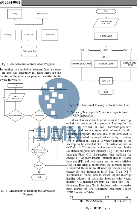
CPU simulation program that is developed in this research has architecture component as followed [4]:
ControlTrack, which is a module where user can interact with the simulation program like inputting instruction, and controlling the work of classCpu, CMemory, and IOAddressSpace
StatusTrack, which is playing the role as a window to display the status and value of all registers in classCpu and contents of Cmemory
ClassCpu, which is a component or a class in the simulation program that do the execution of instructions given
CMemory, which is a component or a class in the simulation program that has a role as data storage or memory
IOAddressSpace, which is a component or a class in the simulation program that has a role as I/O address space as means to access the I/O ports
71 IJNMT, Vol. IV, No. 2 | December 2017
ISSN 2354-0082
classCpu
CMemory ControlTrack StatusTrack
File Instruction Set
IOAddressSpace
Fig. 1. Archictecture of Simulation Program In running the simulation program, there are steps that the user will encounter in. Those steps are the mechanism of the simulation program described in the following flowcharts
Start
Input Instruction
More Instruction? Execute All?
Trace Next Instruction
Restart? No
No
Ya Yes
Yes
End No Trace Next Instruction
All instructions have been traced? See Execution
results
No See Execution
results
Yes
Fig. 2. Mechanism in Running the Simulation Program
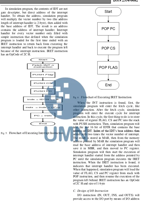
Start
Initialitation ICC = 0
Fetch Cycle
Execute (INT) Cycle Execute (IRET) Cycle ICC == 2 ICC? ICC == 3
ICC == 1
Execute Cycle
ICC = 0
End
Fig. 3. Mechanism of Tracing the Next Instruction
B. Design of Interrupt (INT) and Interrupt Return (IRET) Instruction
Interrupt is an instruction that is used to interrupt or halt the execution of a program. Interrupt by the sources is divided in two, hardware-generated interrupt and software-generated interrupt. In this simulation program, the one able to be simulated is software-generated interrupt, which is by executing INT n instruction, with n is vector number of the interrupt to be executed. The INT instruction has an OpCode of 1C H and instruction size of 3 byte. In this simulation program, Set Interrupt Flag (STI) and Clear Interrupt Flag (CLI) instructions that facilitate the change of flag from Enable Interrupt (EI) to Disable Interrupt (DI) and vice versa, are not yet available. Also, in this simulation program, the interrupt process is assumed the same to all interrupt vector and flag change for this instruction is IF flag. If an INT n
instruction is found, then to search for the interrupt handler address of particular interrupt with vector number n, simulation program will look into IDTR (Interrupt Descriptor Table Register), which contains base address of IDT (Interrupt Descriptor Table). IDTR has size of 24-bit
23 8 7 0
IDT Base Address IDT Limit
IJNMT, Vol. IV, No. 2 | December 2017 72
ISSN 2354-0082
In simulation program, the contents of IDT are not gate descriptor, but direct address of the interrupt handler. To obtain the address, simulation program will multiply the vector number by two (the address length of interrupt handler is 2-byte), then added with the base address of IDT. The result is an address contains the address of interrupt handler. Interrupt handler for every vector number only filled with simple instruction that defined when the simulation program is loaded for the first time ended with an IRET instruction to return back from executing the interrupt handler and back to execute the program left because of the interrupt instruction. IRET instruction has an OpCode of 2C H.
Start
PUSH Flag
PUSH CS
PUSH PC
indx = IDTR >> 8 Fetch INT n
instruction
indx = indx + (2*n)
PC = indx
End
Fig. 5. Flowchart of Executing Interrupt Instruction
Start
POP PC
POP CS
POP FLAG
End
Fig. 6. Flowchart of Executing IRET Instruction When the INT instruction is found, first, the simulation program will enter the fetch cycle, like other instruction. After the fetch cycle, simulation program will enter the execute cycle for interrupt instruction. In this cycle, the first thing to do is to store the value of register FLAG, CS and PC into the stack with PUSH instruction. Then, simulation program will take the last 16 bit of IDTR that contains the base
address of IDT. Index of the IDT’s base address then
added with two times the vector number of interrupt. The result is stored in MAR, then from the memory address pointed by MAR the simulation program will read the base address of interrupt handler and then save it in MBR, and then moved to PC register. Simulation program will then start the execution of interrupt handler started from the address pointed by PC until the simulation program executes the IRET instruction. When the IRET instruction is found, it indicates that interrupt handler has been executed. When that happened, simulation program will load the value of FLAG, CS and PC register from stack with POP instruction, and then resume the execution of the program left behind. IRET instruction has an OpCode of 2C H and size of 1-byte
C. Design of I/O Instruction
73 IJNMT, Vol. IV, No. 2 | December 2017
ISSN 2354-0082
Used to move one item (byte, word or double word) between I/O ports and general purpose register. Included in this group are IN and OUT instructions
Used to move string of item (string of byte, word or double word) between I/O ports and memory. Included in this group are INS and OUT instructions
In the simulation program, group of I/O instruction able to be handled are only IN and OUT instructions
IV. IMPLEMENTATION AND TESTING
A. Implementation of Class CMemory
In class CMemory, there is an array that acts as storage but has private attribute. The data in this array can only be accessed using functions or methods contained in this class. The array has the capacity of 4 KB (4096 byte). The functions or methods in this class have a function to read or write data in the array. There are four main methods in this class, methods to write and read byte like writeByte and readByte, and methods to write and read word like writeWord and readWord
B. Implementation of Instruction
The main focuses of this research are interrupt instruction (INT), interrupt return instruction (IRET) and I/O operations
1) Implementation of Interrupt and Interrupt Return
Interrupt is an instructions used to halt the running program. Based on the sources, interrupt is divided into two type, hardware generated interrupt and software generated interrupt. In simulation program, the type that can be handled is software generated interrupt, called through INT n instruction. n is the vector number of the interrupt called. Vector number is allowed only in the range from 0 to 1F H. Interrupt in simulation program is still simple, because there is no proper interrupt handler like the one in Intel processor
The interrupt process in this simulation program only shows how the interrupt handler is called through INT instruction. In this simulation program there no instructions to facilitate change in FLAG from EI (Enable Interrupt) to DI (Disable interrupt) vice versa like STI (Set Interrupt Flag) and CLI (Clear Interrupt Flag). In this simulation program, the interrupt process is considered the same for all interrupt vector and FLAG changed in this instruction is IF flag.
After the process of calling the interrupt handler, the simulation program then proceeds to executing the interrupt handler. Interrupt handler in this simulation program only contains simple instructions ended with IRET instruction, to return the value of register FLAG,
CS and PC back to the value before the interrupt instruction enter execute cycle.
2) Implementation of I/O Instructions
I/O instructions that can be handled by simulation program are IN, and OUT. IN instruction is an instruction to read the value of I/O address space with the address pointed by displacement or general purpose register and store it in general purpose register. And OUT Instructions will write the value of a general purpose register into I/O address space with address pointed by displacement or general purpose register.
C. Testing of Simulation Program
Testing for the simulation program is done to see if the program can run according to expectations. Testing is done by trying to execute variety of instructions that contained in file instruction set. The following is an example of instructions run by the simulation program.
TABLE I. Testing Of Arithmetic Operations ADD
TABLE II. Testing of Boolean Operation NOT
TABLE III. Testing of Stack Operations PUSHF
IJNMT, Vol. IV, No. 2 | December 2017 74
ISSN 2354-0082
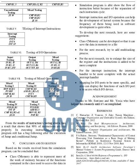
CMP R3, 5 CMP [R1+1], R2 CMP R3,R3
Unconditional Testing
Mixed Testing
JZ 10 CMP R1,R2
CMP R1,R1 JZ 10
TABLE V. TEsting of Interrupt Instructions Interrupt
Testing
INT 0 INT 8 INT 1F
TABLE VI. Testing of I/O Operations Input
Testing
Output Testing
Mixed Testing
IN R1, 45 IN R3, 12 IN R7, 2FF
OUT 12, R4 OUT 123, R6 OUT 7FF, R3
OUT 12, R1 IN R5, 12 IN R5,R1
TABLE VII. Testing of Mixed Operations Mixed
Testing I
Mixed Testing II
Mixed Testing III
MOV R1,R2 PUSHF CMP R1,R2
JE 10
CMP R1,R2 AND R1, [R2+5]
INT 5 CMP R4,R5
SUB R5,R6 OUT 12, R5 IN R7, 12 MUL R7,6
Mixed Testing IV
Mixed Testing V
SUB R1,R1 INT 1F CMP R1,[R2+4]
JZ 10
PUSH R1 ADD R1,5 MOV R2, R1
POP R1
From the results of instruction’s testing above, has a result that shows that 90% of instructions are run properly. In executing instructions, simulation program still has a bug following after the execution of Jump and conditional Jump.
V. CONCLUSION AND SUGESSTION
Based on the results received from the simulation program, can be concluded that:
Class CMemory is able to represent more of the work of memory because of the functions contained in the class used to access the data in the memory
Simulation program is able show the flow of instruction better because of the separation of each instruction cycle
Interrupt instruction and I/O operation can help the development of kernel system because the frequency of them being used in software development is quite often.
To develop the next research, here are some suggestions:
Class CMemory can be developed so that it can save the data in memory to a file
For the next research, try to add multitasking process.
For the next research, try to enlarge the size of the register and the instructions is added to be more complete
For the interrupt instruction, the interrupt handler to be more complete with the actual interrupt handler
Mapping for I/O ports to be more specific, and also can display the functions of each I/O port is to access which I/O device.
ACKNOWLEDGMENT
Thanks to Mr. Sutrisno and Mr. Yosia who have
helped this research until it’s accomplished
REFERENCES
[1] C. Hamacher, Z. Vranesic, S. Zaky. Naraig Manjikian ,
Computer Organization and Embedded Systems 6th Edition; McGraw-Hill, 2012
[2] B. Brey. The Intel Microprocessors , Architecture, Programming, and Interfacing , 8th Edition. Pearson, 2008 [3] W.Stallings. Computer Organization and Architecture, 9th
Edition Pearson , 2012
[4] F.A.Halim , Sutrisno, “Fundamental Characteristic of Central Processing Unit Simulation as a Basic Stage of Making Kernel”, Publish in Konferensi Nasional Sistem & Informatika (KNS&I 2010), 12-13 Nov 2010, Bali
[5] Intel, IA-32 Intel® Architecture Software Developer’s Manual Volume 3: System Programming Guide, Denver: Intel Corporation, 2004
[6] Intel,IA-32 Intel 80386 Reference Programmer's,: I/O Instruction , https://pdos.csail.mit.