Robust hydro-thermal power system controller
considering energy capacitor system and wind power
source
Thongchart Kerdphol*, Yaser Soilman Qudaih,
Khairudin H. Basri and Yasunori Mitani
Department of Electrical and Electronics Engineering, Kyushu Institute of Technology,
1-1, Sensui-cho, Tobata-ku, Kitakyushu-shi, Fukuoka, 804-8550, Japan
Email: [email protected] Email: [email protected] Email: [email protected] Email: [email protected] *Corresponding author
Abstract: This paper presents the method to design the robust controller for the hydro thermal system considering interconnection of two areas. The feasibility of using the automatic generation control with energy capacitor system is implemented to both areas. Wind turbines are considered to be one of the most used alternative sources of energy to solve global warming worldwide. The output of wind turbines depends on the weather condition which causes large fluctuation in the power output when WTs connect to the system. So, the system should be capable of handling uncertainties caused by the wind turbines and load variations. H∞ loop-shaping method is designed as the proposed controller which is used to regulate and improve system stability in the hydro thermal power system. Results demonstrate that the hydro thermal system with ECS-based H∞-controller gives higher system stability and more robustness than the hydro thermal system with ECS-based PID controller.
Keywords: energy capacitor system; ECS; H∞-LSDP; power system oscillation; robust control; wind energy.
Reference to this paper should be made as follows: Kerdphol, T., Qudaih, Y.S., Basri, K.H. and Mitani, Y. (2015) ‘Robust hydro-thermal power system controller considering energy capacitor system and wind power source’, Int. J. Process Systems Engineering, Vol. 3, Nos. 1/2/3, pp.90–109.
Biographical notes: Thongchart Kerdphol received his BEng and MEng from Kasetsart University, Bangkok, Thailand in 2010 and 2012. Currently, he is pursuing his DEng degree at Kyushu Institute of Technology. His research interests are in the area of the application of artificial intelligence in power systems, power system stability, smart grid, renewable energy, power system dynamics and controls.
Technology (KIT), Japan. His research interests are in the area of the application of artificial intelligence in power systems, power system stability, dynamics and controls and smart grid.
Khairudin H. Basri received his ST (equal to BSc degree) from Sriwijaya University, Palembang, Indonesia and MSc from The University of Manchester (formerly UMIST), UK in 1995 and 1999, respectively. Currently, he is pursuing in DEng degree at Kyushu Institute of Technology, Japan. His research interests are in the area of the application of artificial intelligence in power systems, power system stability, dynamics and controls and smart grid. He is a student member of IEEE.
Yasunori Mitani received his BSc, MSc and DEng in Electrical Engineering from Osaka University, Japan in 1981, 1983 and 1986, respectively. He was a Visiting Research Associate at the University of California, Berkeley, from 1994 to 1995. He is currently a Professor at the Department of Electrical Engineering and Electronics, Kyushu Institute of Technology (KIT), Japan. At present, he is the Head of Environmental Management Center of KIT. His research interests are in the areas of analysis and control of power systems. He is a member of the Institute of Electrical Engineers of Japan and IEEE.
This paper is a revised and expanded version of a paper entitled ‘Robust hydro thermal power system controller considering energy capacitor system and wind power source’ presented at the IEEE on Smart Energy Grid Engineering (SEGE‘14), UOIT, Oshawa, Canada, 11–13 August 2014.
1 Introduction
Currently, many countries have increased their capacity to generate electricity from renewable sources (Gu et al., 2011; Francisco et al., 2015). The main target is to reduce the amount of CO2 injected to the atmosphere and to eliminate the greenhouse effect
mainly caused by the huge consumption of fossil oil. Wind energy is one of the renewable energies used broadly because it is sustainable energy and environmental friendly. The numbers of installed wind power sources are increasing around the world. However, the wind power output affected by environmental change and weather condition. So, wind energy is not used as main energy sources because the electrical power obtained from the wind energy is fluctuating which leads to the oscillation of power system frequency (Lalor et al., 2005). In this case, the H∞ loop-shaping design procedure (H∞-LSDP) controller is proposed to the system in order to handle such a power fluctuation.
environmental friendly (Notomo et al., 2001; Qudaih et al., 2011; Yujun et al., 2014). This paper investigates the dynamics performance of both PID and H∞-LSDP controllers and takes the advantage of the ECS in an interconnected hydro-thermal power system to improve the system stability.
According to the power fluctuation from wind energy and load variations, the development in robust control theory has provided powerful tools such as H2, H∞ and
mixed H2/H∞ techniques for power system load frequency control design. The resulting
robust control can play an important role in system security and reliable operation. The main target of robust control design is to develop new load frequency control methods for multi-area power systems (Glover and McFarlane, 1989; McFarlane and Glover, 1990; Bevrani, 2009; Soumya et al., 2014). To overcome the fluctuation caused by wind energy and load variations and to improve the system stability, the ECS-based H∞-LSDP controller is considered.
In the past, two area power systems (e.g., thermal-thermal area or hydro-thermal area) have been considered as research studies. In such a system where one of the areas is hydro and the other is either thermal or hydro, interconnected via a tie line. The speed governor acts as the primary controller which balances the generation with the demand so as to control the system frequency. Nevertheless, the secondary controller matches the frequency and tie line power on (IEEE Committee Report, 1970; IEEE PES Committee Report, 1973; IEEE PES Working Group, 1992). Automatic generation control (AGC) under analysis is composed of an interconnection of two areas. AGC of interconnected power systems is increasing significantly in modern power system. Increasing demand in power system and the complexity of load profiles have required the design of interconnected power systems. The main target of AGC system is to quickly match the generation of the system with changing load demand. So, the reliability of the power system can be improved (Green, 1996; Karnavas and Papadopoulos, 2002; Nizamuddin and Bhatti, 2014).
This paper presents the H∞-LSDP controller design of hydro-thermal power system with the ECS. The H∞-LSDP is designed and implemented as the proposed controller. The main purpose of H∞-LSDP controller is to control and reduce the oscillation of the system frequency after the installation of wind turbines (WTs) and load variations. The power from WTs is applied to the system. For the performance verification, the ECS-based PID controller is selected to be the candidate for comparison with parameters optimally tuned by genetic algorithm (GA) (Chiang and Safonov, 1988) in order to compare the dynamic stability in the hydro-thermal power system (Goldberge, 1989; Dulal et al., 2012).
2 Dynamic model of interconnected hydro-thermal power system with the ECS
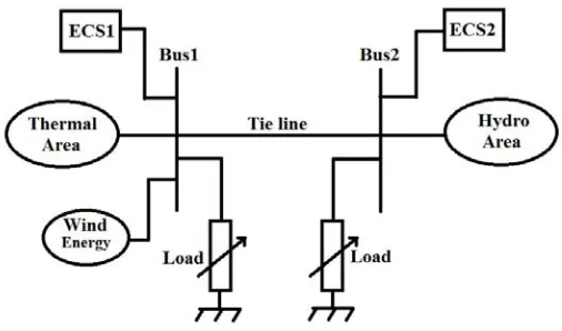
Based on Figure 1, the hydro-thermal power system with ECS is implemented in both of two areas. A load variation is connected to each area. The interconnected power systems consist of different control areas that are connected though tie line in order to transfer power and improve system stability (Elgerd, 1982; Elgerd and Fosha, 1970a, 1970b). Figure 1 Hydro-thermal power system incorporating the ECS and wind power source
The thermal power system is consisted of the speed governor acting as a primary controller. It helps to match the generation and demand by regulating the steam input to the turbine. The reference power setting of the governor is changed by the secondary controller in order to tune the system frequency.
2.1 Thermal power system formulation
The speed governor equation is:
1 1 1
1 1
ΔPG = ΔPref − Δf
R (1)
The hydraulic amplifier equation is:
1 1
1 1
⎛ ⎞
Δ =⎜ ⎟Δ
+
⎝ ⎠
H G
G
P P
sT (2)
The non-reheat turbine equation is:
1 1
1 1
⎛ ⎞
Δ =⎜ ⎟Δ
+
⎝ ⎠
T H
T
P P
sT (3)
2.2 Hydro power system formulation
2 2 2
2
1
ΔPG = ΔPref − Δf
R (4)
The hydraulic amplifier equations are:
2
The hydro turbine equation is:
2 2
The power output from the turbine becomes an input to the generator in order to feed electrical power to the system. This equation can be shown as:
(
)
; where 1, 2The power transfer equation between two areas via tie line is expressed as:
(
)
Because of load variations, each area experiences frequency deviation aside from tie line power deviation. This problem can be solved by using area control error (ACE). This equation followed in this paper is shown as:
, ; where 1, 2,
ΔACEi = ΔPtie i+ Δβi fi i= (10)
2.3 WT model
WT generator output is dependent on the wind speed. The characteristic of WT generator is demonstrated in Senjyu et al. (2005).
The WT system has much nonlinearity. Through the pitch controller, WT output power varies between maximum or rated power, and zero power to respond to utility grid frequency oscillations. Thus, the pitch angle set point is nonlinearly limited by these boundaries. The pitch system tunes the pitch angle and introduces nonlinearity. The WT can be simplified to a first order system. In this article, the transfer function of the WT is represented by a first-order lag (Lee and Wang, 2008) as:
2.4 Energy capacitor system
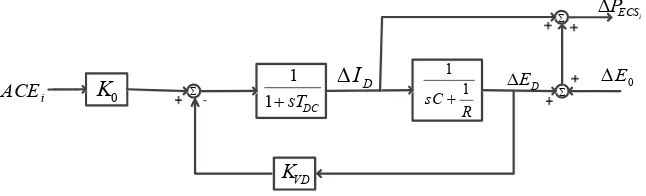
ECS collects the energy in its electrostatic field created at its plates in response to resolved potential across it. Figure 2 demonstrates the structure of the ECS.
Figure 2 ECS mathematical model
Σ
The ACE is fed as the control signal to the ECS unit. The relative equation between ACE and the ECS unit can be expressed as:
(
)
After a quick load variation, the restoration time of capacitor bank to normal voltage is not so fast in either of the areas. For fast restoration, a negative feedback is implemented through the voltage deviation (∆ED) control loop in the ECS as in Figure 2. The power
output from the ECS unit is shown as:
(
0)
• R1, R2 are the regulation of speed governor constant in the thermal and hydro power
• ΔPH1,ΔPH2 are the hydraulic value power deviation of the thermal and hydro power
system respectively
• ΔPT1,ΔPT2 are the turbine power deviation of the thermal and hydro power system
respectively
• ΔPHg is the hydro governor power deviation of the hydro power system respectively
• ΔPECS1,ΔPECS2 are the ECS power deviation of the thermal and hydro power system
respectively
• ΔPtie is the tie line power deviation
• ΔPD1,ΔPD2 are the load power deviation of the thermal and hydro power system
respectively
• ΔACE1, ΔACE2 are the ACE deviation of the thermal and hydro power system
respectively
• ΔID1,ΔID2 are the current deviation of the ECS in the thermal and hydro power
system respectively
• ΔED1,ΔED2 are the voltage deviation of the ECS in the thermal and hydro power
system respectively
• TG is the governor time constant of the thermal power system
• TT is the non-reheat turbine time constant of the thermal power system
• T1, T2, TR are the time constant of the hydro governor
• TW is the time constant of the hydro turbine
• T is the synchronising coefficient
• Tdc is the DC voltage time constant of the ECS unit
•
1
P
T , 2
P
T are the power system time constant of the thermal and hydro power system respectively
• KP1,KP2 are the power system gain of the thermal and hydro power system
respectively
• KECS is the ECS gain of the thermal and hydro power system
• KVD is the voltage deviation gain of the ECS in the thermal and hydro power system
• C is the capacitor of the ECS
• R is the resistance of the ECS
• KWT is the gain of the WT transfer function
• TWT is the time constant of the WT transfer function.
•
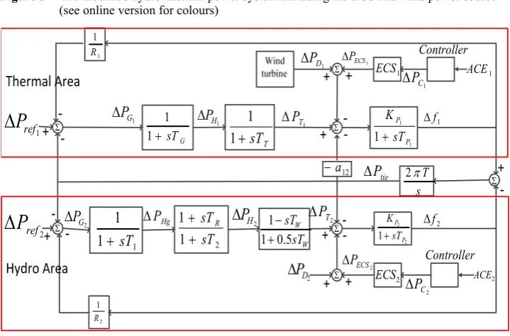
The modified hydro-thermal power system including the ECS and wind power source is linear and can be shown in Figure 3. The values of parameters are shown in Appendix. Figure 3 The modified hydro-thermal power system including the ECS and wind power source
(see online version for colours)
1
3 Proposed control strategy
3.1 Robust controller designed by H∞-LSDP
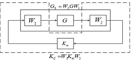
The nominal plant of the system is G. There are two weighting functions W1 (i.e., the lead
compensation) and W2 (i.e., the lag compensation). The shaped plant GS = W2GW1 is
enclosed by the solid line and the proposed robust controller KC = W1K∞W2 is enclosed by
the dashed line as shown in Figure 4.
K∞ is the H∞-LSDP transfer function. The weighting functions are W1 and W2 which
Figure 4 Plant GS and the robust controller design
∞
K
G
1
W W2
2 1KW
W KC= ∞
1 2GW W GS =
The next process of designing H∞-LSDP is shaping the plant GS using the left co-prime of
the nominal plant = −1
s l l
G M N where GP is expressed as:
(
) (
)
{
1}
: 1 /
−
∞
= + Δ + Δ Δ Δ ≤
p l M l N N M
G M N γ (16)
where ∆M and ∆N are the uncertainty transfer functions in the nominal plant G.
From the stability definition of H∞-LSDP, GP and KC can be synthesised as in
Figure 5. The objective function of the robust controller design does not only provide stability to the plant G, but also keeps the stability of GP of 1/γ as in equation (16) which
is the robust stability index.
The robust stability margin of the power system with uncertainty is specified by the minimum value of γ, that is γmin. Thus, γmin is the uncertainty of the power system having the maximum size that can be closed-loop stabilised as in Figure 5. The γmin can be calculated as follows:
( )
min = 1+ max
γ λ XZ (17)
where λmax(XZ) is the maximum value of XZ for the minimal state space realisation (A, B, C, D) of the nominal plant G. The values of X and Z are unique positive solutions to the generalised control algebraic Riccati equation.
Figure 5 Robust stability problem H∞-LSDP
The generalised control algebraic Riccati equation.
The generalised filtering algebraic Riccati equation.
(
A BS D C− −1 T)
T Z+Z A BS D C(
− −1 T)
T −ZC R CZT −1 +BS B−1 T =0 (19)where R = I + DDT and S = I + DTD. In order to ensure the robustness stability of the nominal plant G, the weighting function is selected so that 1 ≤ γmin < 4.0 (Glover and McFarlane, 1989).
The robust controller gain can be designed from (20).
( )
1(
)
( )
1Due to the large power system, the designed controller is normally in a very high order. Thus, the obtaining controller order needs to be reduced by using the appropriate reduction algorithm in robust control toolbox of MATLAB (Chiang and Safonoy, 1988).
3.2 PID controller with parameters optimally tuned by GA
The proportional-integral-derivative controller (PID controller) is a control loop feedback widely used in industrial and power plant control system. Thus, this paper selected it as the comparator in order to compare the results with the proposed controller.
GA is stimulated by the basic principles of natural development. GA works with a group of population of candidate solutions represented by group of chromosomes. The initial population consists of generated individuals. The fitness function of each individual is calculated in the current position of every iteration. The population is adjusted in stages to generate a new population for next iteration. The adjustment is done in three steps. The first is selection, the second is crossover; and the third is mutation. In the first process, selection is implemented as many times as there are individuals in the population. In the next process, crossover is applied by selection and combination of new individuals. The combination is done by random selection. In the final process, mutation changes the values in a randomly selected position on an individual. This process continues until one of the stopping conditions are met or global minimum is reached. Moreover, as GA does not require any information about structure of the function to be optimised and it is quick to implement (Goldberge, 1989; Dulal et al., 2012). Thus, this paper used GA in the tuning procedure to find the suitable parameters of KP, KI and KD.
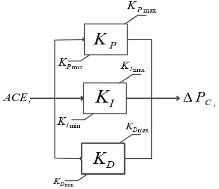
From Figure 6, the inputs of controller are ACE1, ACE2 and the outputs of controller are
The performance index or fitness function is formulated by the integral time domain. The fitness function (J) is applied for optimising the gain of the PID controller and this can be expressed as:
(
2 2 2)
Under the constraints of:
min max
power system. The GA tool provided in MATLAB 2010 is used for optimising the fitness function (J).
Figure 6 Structure of the supplementary PID controller
i
4 Simulation results
This paper makes the comparison between the hydro-thermal power system without the ECS and another one equipped the ECS-based H∞-LSDP controller so as to illustrate the efficiency of the proposed method. The performance verification is compared against the ECS-based PID controller tuned by GA. The WTs which add to the thermal power system as the disturbance are shown in Figure 7.
The K∞ of ∆Pref1 is evaluated by the ECS-based H∞-LSDP controller which can be
• Controller ΔPCi :
2154 12 0.20
63 0.30 0.10
∞ = − +
+ + +
K
s s s (23)
• Weighting function:
1 2
50 5
, 1
0.3
+
= =
+
s
W W
s (24)
Figure 7 Disturbance from the WTs
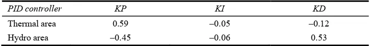
Table 1 shows the optimal values of PID controllers which tuned by GA. Table 1 Parameters used in the PID controllers
PID controller KP KI KD
Thermal area 0.59 –0.05 –0.12
Hydro area –0.45 –0.06 0.53
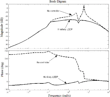
Based in Figure 8, the magnitude and phase of the frequency response without the H∞-LSDP controller have less damping which yield to resonance peak of 9 dB and 630 deg, respectively. After including the H∞-LSDP controller, the resonance peak of the magnitude and phase is decreased in Figure 8.
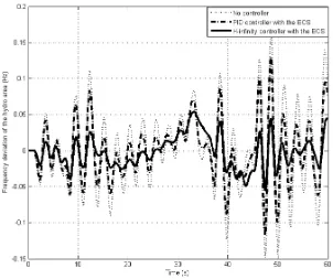
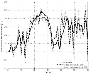
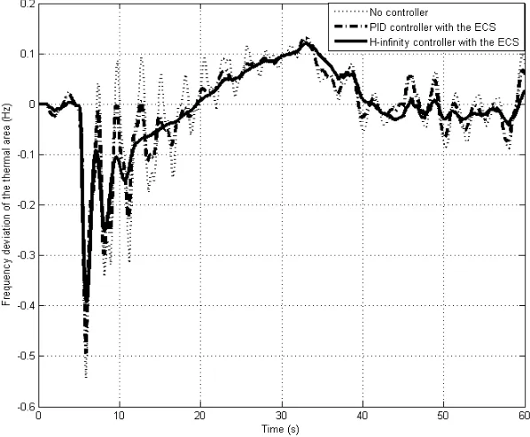
power of the system is also increased, which consequently affects the frequency of the power system. The frequency and power responses of the hydro-thermal power system are presented in Figures 9 to 13 accordingly. From the figures, it can be seen that the ECS-based H∞-LSDP controller can overcome fluctuations caused by 5% variation of wind power better than the hydro-thermal power system with the ECS-based PID controller. Hence, the results of the ECS-based H∞-LSDP controller indicate a more desirable performance as compared to the ECS-based PID controller.
Figure 8 Frequency response of the hydro-thermal power system with the ECS designed by H∞-LSDP
Figure 9 Frequency response of the thermal power system with 5% variation of the wind power
Figure 11 Tie line power response of the hydro power system with 5% variation of the wind power
Figure 13 Power response of the hydro power system with 5% variation of the wind power
Figure 15 Frequency response of the hydro power system with 5% variation of the wind power and 10% variation of load in the hydro power system
Figure 17 Power response of the thermal power system with 5% variation of the wind power and 10% variation of load in the hydro power system
5 Conclusions
The robust hydro-thermal power system controller design with the ECS is proposed in order to improve system stability under wind power disturbance with 5% variation of installed capacity. In this paper, the performance of controller is compared with the ECS-based PID controller. The results are shown that the ECS-based H∞-LSDP controller provides smooth and robust system stability compared to the ECS-based PID controller. After the hydro power system has been adjusted to 10% of its load, the ECS-based H∞-LSDP controller can still preserve the performance better than the ECS-based PID controller. Moreover, it has been shown that the system frequency and tie line power oscillations caused by the variations of wind power and loads can be reduced in both the areas by the ECS-based H∞-LSDP controller. Therefore, the AGC performance of hydro-thermal power system can be improved by the ECS-based H∞-LSDP controller.
References
Bevrani, H. (2009) Robust Power System Frequency Control, Springer, Germany.
Chacra, F., Bastard, P., Fleury, G. and Clavreul, R. (2005) ‘Impact of energy storage costs on economical performance in a distribution substation’, IEEE Trans. Power System, Vol. 20, No. 2, pp.684–691.
Chiang, L.Y. and Safonov, M.G. (1988) Robust Control Toolbox, MathWorks, South Natick, MA. Dulal, D., Roy, A. and Sinha, N. (2012) ‘GA based frequency controller for solar
thermal-diesel-wind hybrid energy generation/energy storage system’, Int. J. Electr. Power Energy Syst., Vol. 43, No. 1, pp.262–279.
Elgerd, O.I. (1982) Electric Energy Systems Theory: An Introduction, 2nd ed., McGraw-Hill, New York, NY.
Elgerd, O.I. and Fosha, C. (1970a) ‘Optimum megawatt-frequency control of multiarea electric energy systems’, IEEE Trans. Power Apparatus System, Vol.PAS-89, No. 4, pp.556–563. Elgerd, O.I. and Fosha, C. (1970b) ‘The megawatt-frequency control problem: a new approach via
optimal control’, IEEE Trans. Power Apparatus System, Vol. PAS-89, No. 4, pp.563–577. Francisco, D., Malanie, H., Andreas, S. and Oriol, G. (2015) ‘Coordinated operation of wind
turbines and flywheel storage for primary frequency control support’, Int. J. Electr. Power Energy Syst., Vol. 68, No. 1, pp.313–326.
Glover, K. and McFarlane, D (1989) ‘Robust stabilization of normalized coprime factor plant description with H∞-bounded uncertainty’, IEEE Trans. Automatic Control, Vol. 34, No. 8, pp.821–830.
Goldberge, D.E. (1989) Genetic Algorithm in Search, Optimization and Machine Learning, Addison-Wesley Publishing Company Inc., USA.
Green, R.K. (1996) ‘Transformed automatic generation control’, IEEE Trans. Power Systems, Vol. 11, No. 1, pp.1799–1804.
Gu, W., Wang, R., Sun, R. and Li, Q. (2005) ‘Wind power penetration limit calculation based on stochastic optimal power flow’, International Review of Electrical Engineering (IREE), Vol. 6, No. 4, pp.1939–1945.
IEEE Committee Report (1970) ‘Standard definitions of terms for automatic generation control on electrical power systems’, IEEE Trans. Electric Power Apparatus System, Vol. 89, No. 4, pp.1356–1364.
IEEE PES Committee Report (1973) ‘Dynamic models for steam and hydro turbine in power system studies’, IEEE Trans. Power Apparatus System, Vol. 92, No. 1, pp.455–463.
IEEE PES Working Group (1992) ‘Hydraulic turbine and turbine control models for system dynamics’, IEEE Trans. Power System, Vol. 92, No. 1, pp.455–463.
Karnavas, Y.L. and Papadopoulos, D.P. (2002) ‘AGC for autonomous power system using combined intelligent techniques’, International Journal of Electrical Power System Research, Vol. 62, No. 3, pp.225–239.
Lalor, G., Mullane, A. and O’Malley, A. (2005) ‘Frequency control and wind turbine technologies’, IEEE Trans. Power Systems, Vol. 20, No. 4, pp.1905–1913.
Lee, D. and Wang, L. (2008) ‘Small-signal stability analysis of an autonomous hybrid renewable energy power generation/energy storage system part I: time-domain simulations’, IEEE Trans. Energy Conversion, Vol. 23, No. 1, pp.311–320.
McFarlane, D. and Glover, K. (1990) ‘Robust controller design using normalized coprime factor plant descriptions’, Lecture Notes in Control and Information Sciences, Vol. 138, Springer-Verlag.
Notomo, S., Nakata, H., Yoshioka, K., Yoshida, A. and Yoneda, H. (2001) ‘Advanced capacitors and their application’, Journal of Power Sources, Vol. 97, No. 1, pp.807–811.
Qudaih, Y., Elbaset, A. and Hiyama, T. (2011) ‘Simulation studies on ECS application in a clean power distribution system’, Int. J. Electr. Power Energy Syst., Vol. 33, No. 1, pp.43–54. Senjyu, T., Nakaji, T., Uezato, K. and Funabashi, T. (2005) ‘A hybrid power system using
alternative energy facilities in isolated island’, IEEE Trans. Energy Conversion, Vol. 20, No. 2, pp.406–414.
Soumya, M., Nand, K. and Prakash, R. (2014) ‘Robust H-infinite loop shaping controller based on hybrid PSO and harmonic search for frequency regulation in hybrid distributed generation system’, Int. J. Electr. Power Energy Syst., Vol. 60, No. 1, pp.302–3016.
Tripathy, S., Kalantar, M. and Balasubramanian, R. (1991) ‘Dynamics and stability of wind and diesel turbine generators with superconducting magnetic energy storage unit on an isolated power system’, IEEE Trans. Energy Conversion, Vol. 6, No. 1, pp.46–51.
Yujun, L., Zeren, Z., Yong, Y., Yingyi, L., Hairong, C. and Zheng, X. (2014) ‘Coordinated control of wind farm and VSC-HVDC system using capacitor energy and kinetic energy to improve inertia level of power systems’, Int. J. Electr. Power Energy Syst., Vol. 59, No. 1, pp.79–92.
Appendix
A System data
TG = 0.08 s, TT = 0.3 s, T1 = 42.5 s, T2 = 0.515 s, TR = 5 s, TW = 1 s, T = 0.0855 s,
Tdc = 0.05 s, TP1 = 20 s, TP2 = 20 s, KP1 = 120 Hz/pu, KP2 = 120 Hz/pu, a12 = –1,
β1 = β2 = 0.424, R1 = R2 = 2.4 Hz/pu, PThermal = PHydro = 1,200 MW.
B Energy capacitor system