Numerical Estimation of Rolling Load and Torque for Hot Flat Rolling of
Hcss316 at Low Strain Rates Based on Mean Temperature
1
Sadiq, T O,
aFadara T G,
bAiyedun, P. O and
*Idris, J
1Manufacturing Department, Engineering Materials Development Institute
KM4, Ondo Road, P.M.B 611, Akure, Ondo State, Nigeria
a Department of Mechanical Engineering, College of Engineering
Federal Polytechnic, Ede, Osun State, Nigeria
b Department of Mechanical Engineering, College of Engineering
Federal University of Agriculture, Abeokuta, Ogun State, Nigeria
*Faculty of Mechanical Engineering,
Universiti Teknologi Malaysia, UTM, Skudai 81310, Johor Bahru, Malaysia
* Corresponding Author: +6075534659
E-mail addresses: [email protected] (T.O. Sadiq), [email protected] (J. Idris)
Keywords: Rolling Process, Numerical Estimation, Rolling Load, Torque, Strain Rates, Yield Stress, Zener–Hollomon Parameter.
ABSTRACT. Numerical estimation of rolling load and torque often showed large discrepancies when compared with experimental values. This was attributed to difficulty in estimating the mean rolling temperature from the available data. This work is thus directed at obtaining a good estimate for the mean rolling temperature which can effectively be used for load and torque estimates. Hot flat rolling stimulation by use of the Bland and Ford’s cold rolling (HRBF) theory confirmed the reverse sandwich effect in selected carbon steels at low strain rates. In this work, the effect of pass reduction on rolling temperature distribution, yield stress and rolling load were studied for AISI Type 316 stainless steel (HSCSS316). For this new simulation, at low and high strain rates, results showed that the ratio of experimental to calculated rolling load and torque were higher at lower reduction than at higher reduction. These results confirmed excess load and torque in the hot rolling of HSCSS316 low reductions. The results obtained from Hot Rolling Bland and Ford’s Theory based on Root Mean Square rolling temperature were in good agreement with values obtained using Reverse Sandwich Model and the Reverse Sandwich- Hot Rolling Bland and Ford’s Program under the same rolling conditions.
1. INTRODUCTION
It was discovered that measured load and torque were excessive when compared with calculated values using Simple Rolling Theories such as Sims, Bland and Ford, and a simple rolling temperature based on the mean entry temperature into the roll gap [2], for hot flat rolling at low strain rates and low reduction. These Theories all gave correct results for high strain rates range regarded as normal rolling conditions.
The strength of a material is dependent on its microstructure and the condition during testing of which temperature and strain rate are very important. The structure of the material is equally very much dependent on temperature. For hot rolling at low strain rates, the contact times with the rolls become increasingly large and the effect of this is manifested in pronounced temperature variations as slab is being rolled. It can then be concluded that temperature effects are the most important factors during hot rolling at low strain rates. From previously conducted investigations, the cause was traced to the fact that hot rolling at low strain rates actually occur at a temperature much lower than the mean entry temperature into the roll gap.
These low mean rolling temperatures lead to higher stress in materials since the strength of the material is dependent on temperature. Consequently, higher load and torque were experienced in material since they are also dependent on the yield stresses. The key to unravelling the mystery is then left to be found in the determination of the correct mean rolling temperature. In this work, efforts are aimed at using a suitable method in summarising the set of temperatures encountered during roll contact time into a single one. This single one is used to obtain the correct flow stress and hence correct load and torque. In clearer language, the best average temperature is desired. This will be done by considering various methods of obtaining averages and using each to ascertain the mean rolling temperature which is most suitable for the computation of loads and torques.
1.2 OBJECTIVES
To estimate the Mean Rolling Temperatures using the different averaging methods and to use these results obtained in estimating Yield Stresses which will be subsequently used in calculating the Rolling Load and Torque. Also, to make comparison between the Rolling Load and Torque with results obtained by other Researchers.
2. METHODOLOGY
2.1 Hot Rolling Bland and Ford’s Theory
The Bland and Ford’s Theory (HRBF) is a cold rolling theory, where sliding takes place throughout the arc of contact. It has however been found to be applicable to a hot rolling situation where sliding exists throughout the roll gap. This is the situation for hot rolling of HCSS316 at 9000C – 12000C; reductions of 0 -15%; strain rates of 0.07 -1.5 ; and geometrical factor of 4.0 – 20.00 as reported in the literatures [2, 3, 4].
Rolling Load (P) and rolling torque (T) are respectively given by equation (1) and (2);
=
∅
+
∅
1
= 2
Where: = . . . 3
= . . . 4
= . . 5
= . + 6
Where;
Α Angle of entry i.e. maximum value of θ in radians K Instantaneous yield stress (N/m2)
θ Angle subtended by a point on roll surface w.r.t. line joining roll centres in radians.
∅ Neutral angles in radians R’ Deformed roll radius (mm) R0 Undeformed roll radius in mm S Normal roll pressure (N/mm2) h1,2 Entry and exit height (mm)
N Number of measured values μ Fractional coefficient
In rolling processes generally, it is vital to know the temperature distribution within the slab. The literatures of previous researchers showed that temperature is the dominant parameter controlling the kinetics of metallurgical transformations and the flow stress of the rolled metal. The mean temperature used by Aiyedun (1984) in Hot Rolling Bland and Ford’s Theory is given in the
equation 8
= + 8
Where: T1 and T2 are entry and exit temperatures.
The true yield stresses for load and torque calculation are respectively given as equations (9) and (10);
= 9
= = 10
Where:
=
r = reduction
The percentage rolling reduction is given as:
= × % 11
2.2 The Reverse Sandwich Model (RSM)
The reverse sandwich model predicts the rolling reduction, rolling temperatures and temperature distribution along the through thickness of HCSS316. Detailed theoretical analyses of the model have been reported [7, 8, 13].
With the specimen partitioned into 17 zones (n = 1 – 17), the model’s prediction of rolling temperature follows equation (12) to (15).
The temperature at the specimen’s core is given as:
Where:
TF Furnace temperature,
TM The mean rolling temperature TS Exist or entry temperature
= + 13
= 14
K Reverse Sandwich Model constant, values of which are functions of the rolling speed. 1 ≤ ≤ 4 15 ≥ ≥ 12, = + . . 15
8 < < 9, = 15
5 ≤ ≤ 7 11 ≥ 9, = + . 15
The rolling speed is related to the reverse sandwich model constant as follow: 9 ≤ ≤ 10, = 1.59 16
≤ ≤ , = . 16
≤ ≤ , = . 16
≤ ≤ , = . 16
Where: V = Peripheral velocity of rolls (mm-1) The approximate empirical equation of Farag and Sellars [9] was used in the model for determination of mean strain rate thus: = . . [ ] . 17
δ = reduction (mm) The Zener-Hollomon parameter was determined for each of the seventeen (17) zones along thickness (Z1 – Z17) using the proposition of Zener and Hollomon equation [2, 3] written as; = = 18
Where:
R = Universal constant (8.314Jkg-1/ K) T = Absolute temperature (0C)
The Z-values are uniquely related to the stress, and, hence the deformation of the material. For HCSS316 specimen under the prevailing rolling condition, Q = 460 KJ/mol. [2, 3, 4]
2.3 Choice of Averaging Method for obtaining Mean Rolling Temperature.
Based on comparison of the results obtained with experimental values for the four averaging methods of harmonic mean method, geometric mean method, arithmetic mean method and root mean square method, the root square method gave the lowest error percentage. Hence was used in Bland and Ford’s Theory to estimate the yield stresses for load and torque and hence rolling load and torque for the various specimens.
2.4 Simulation of the Model
Simulation of the model was carried out using FORTRAN 77. The required input data are rolling speed, roll radius, furnace temperature, initial and final height of the specimen, and specimen width. From the output of the program, the temperature distribution, yield stress validation, rolling load and torque distribution across the thickness of the rolled specimen at different pass reduction are evident.
2.5 Experimental
Data used in validating the new hot rolling simulation was obtained through preliminary metallographic, hot torsion tests, and hot rolling experiments performed on the as-received wrought AISI316 with inclusions of Nb, V and Ti in the temperature range (600 – 1200) 0C and strain rate range of 3.6 X 10⁻³s-1 to 1.4s-1. The wrought material was High Carbon Stainless Steel; ASME SA-240 from Heat 38256-2C, product of G.O. Carlson Inc., P.A., and U.S.A. The material was cut into slabs of small sizes and hot rolled. The hot rolling experiments were performed on two laboratory mills; a 1000KN, 2-high, single stand, reversible mill with rolls of 254.0mm diameter by 266.0mm barrel length and 50T (498KN) capacity, 2-high reversible, Hille 50T rolling mill with rolls of diameter 139,7mm.
3.0 DISCUSSION OF RESULTS
The analyses presented above were used to write a Computer program which gave hot rolling load and torque to a reasonable accuracy. The program made use of experimental and theoretical data from a study of loads and torques for light reduction in hot flat rolling at strain rates carried out by [2] and the results from the reverse sandwich effects in HCSS316 hot flat rolled at low strain rates and low reductions investigated by [13] as input data.
In estimating the correct mean rolling temperature, four averaging methods of harmonic means, geometric mean, arithmetic mean and root mean square were used to calculate mean rolling temperature from the measured temperatures of various specimens of steels during roll contact. Due to the least error involved when compared with experimental values, the root square method was used in Bland and Ford’s Theory to calculate yield stresses and hence rolling loads and torques for the various specimens.
The results presented in Table1 will be discussed under the following headings:
• Rolling Load Estimation
• Rolling Torque estimation
• Results for different Rolling Conditions
3.1 Rolling Load Estimation
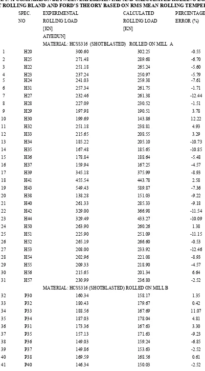
With reference toTable2, the results obtained for rolling load at different hot rolling conditions using the Hot Rolling Bland and Ford’s Theory (based on RMS mean rolling temperature) are in very good agreement with experimental values obtained for the same rolling condition [2]. The results gave a maximum and minimum error of 20.19% and .42% respectively.
3.2 Rolling Torque Estimation
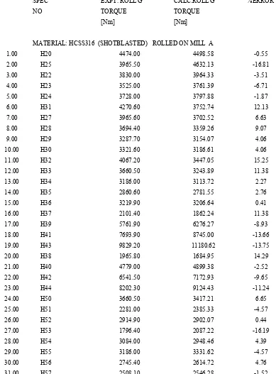
The results obtained for rolling torque estimation at different hot rolling condition using the Hot Rolling Bland and Ford’s Theory (based on RMS mean rolling temperature) are in good agreement with the experimental results obtained [2] under the same rolling condition. The results gave a minimum error of 0.41% and a maximum error of 22.54% (see Table 3).
3.3 Results for Different Rolling Conditions
The results for hot flat rolling of HCSS316 (with Nb, V and Ti inclusions) at low strain rates (0.08 – 1.5) s-1 and low reductions (r ≈10%) on Mills A and B for varying parameters (Appendix A) are sub-divided into the following headings:
• Effect of Variation of Reduction at Low and High Strain Rates
• Effect of Variation of Strain Rates and Furnace Temperature
• Effect of Varying Geometry (W1/h1) at Low and High Strain Rates.
• Effect of Shot Blasted and Smooth Specimen Rolling on Mills A and B at Varying Strain Rates.
3.3.1 Effect of Variation of Strain Rates and Furnace Temperature
For varying strain rates and furnace temperature (TF) values, specimen H20 – H24, H30-H31 and H32 – H36 in that order, the Table 4&5 plotted as Figs. 3.1 to 3.3, show that as the strain rates increases, the ratio of experimental to calculated load decreases on Mill A.
The output also shows that as the furnace temperature increased from 10500C at lowest strain rates i.e. specimen H20 to approximately 12000C (SpecimenH32), the ratio of experimental to calculated to load and torque increased from 1.02 to 1.05 and 0.99 t0 1.18 respectively. (See Tables 4&5). However, the results from rolling on Mill B show no significant variation of the ratio of experimental to calculated load at highest and lowest strain rates (See Table 4).
3.3.2 Effect of Variation of Reduction at Low and High Strain Rates
With reference to Table4 and the plot of Fig. 3.4, the ratio of experimental to calculated load decreases from 1.03 to 0.93 with increase in rolling reduction (specimen H37 – H43) (6.29% – 23.27%) for rolling on Mill A at low strain rates.
Also, at high strain rates, the ratio of experimental load to calculated load decreases from 0.92 to 0.76 as rolling reduction increases (Specimen H38 – H44).
From Table5 plotted as Fig. 3.5 shows that the ratio of experimental torque to calculated torque decreases from 1.17 to 0.90 with increase in rolling reduction (6.87 %– 24.53%) for rolling at low strain rates (Specimen H38 – H44) on Mill A.
3.3.3. Effect of Varying Geometry (W/H0) at Low and High Strain Rates
At a reduction of about 10%, furnace temperature Tf = 11250C at low and high strain rates, the following results were obtained:
From Table4 plotted as Fig.3.6 for specimens H50 - H53, H54 - H57 on Mill A as well as P58 – P61, P62 – P65 on mill B, the average of the ratio of experimental to calculated rolling load is about 1.0 for hot rolling on both Mills at low and high strain rates with geometry (W/H0) varied between 5.0 and 10.00; an indication that there is no systematic effect of geometry variation on the ratio of experimental to calculated load obtained using the Hot Rolling Bland and Ford’s approach.
3.3.4 Effect of Shot-blasted and Smooth Specimen Rolling on Mills A and B at Varying Strain Rates, r ≈ 10%, Tf ≈ 10500C
Results showing the effect of rolling rough and smooth specimen on both Mills at varying strain rates, reduction of about 10% and furnace temperature 10500C are reflected in Table 4 &Table 5. For smooth specimen on mill A (Specimen H01H – H06H), the ratio of experimental to calculated load and torque are higher (average of 1.138 and 1.208 respectively) than the values obtained for rough specimen (Specimen H20 – H24) on the same mill (average of 0.974 and 0.948) respectively).
However, on mill B, Table 4 shows that rough specimens (P30 – P31) have higher experimental to calculated load ratio (average of 1.064) than smooth specimens (P21 – P19) with average value of 0.964.
3.4 COMPARISON OF THE RESULTS BASED ON THE RATIO OF EXPERIMENTAL
TO CALCULATED ROLLING LOAD AND TORQUE [HRBF] WITH RESULTS OF REVERSE SANDWICH MODEL [SHOBOWALE] AND RSM-HRBF [ALAMU]
The accuracy or applicability of the Hot Rolling Bland and Ford’s Theory (based on RMS mean rolling temperature) used in this work was investigated through comparison with results obtained from the Reverse Sandwich Model [13] and RSM-HRBF Theory [7]. The comparison showed that the results obtained were in good agreement.
3.4.1 Ratio of Experimental to Calculated Rolling Load and Torque
The following observations were made from the results presented in Table 7 and 8 plotted as Figs. 3.8, 3.9 and 3.10:
• The ratio of experimental load to calculated load (Pexp/Pcal) values obtained from HRBF Theory (based on RMS mean rolling temperature) was lower than results obtained using RSM-HRBF Theory [7] and Reverse Sandwich Model [13] for all rolling conditions investigated on Mill A and Mill B, see Figs. 3.8 and 3.10. The results obtained from HRBF Theory (based on RMS mean rolling temperature) usually fall below similar lines for the RMS-HRBF Theory [7] and Reverse Sandwich Model [13].
• Also, the ratio of experimental to calculated torque (Gexp/Gcal) values was generally lower using HRBF Theory (based on RMS mean rolling temperature) compared to ratio of experimental to calculated torque (Gexp/Gcal) values using RMS-HRBF Theory [7] and Reverse Sandwich Model [13] for all rolling conditions investigated on mill A, see Figs.3.9.
• Figures 3.8 and 3.10 revealed that the values of load obtained using HRBF Theory (based on RMS mean rolling temperature) compared to RMS-HRBF Theory [7] and Reverse Sandwich Model [13] values are closer to experimental values.
4.0 CONCLUSION
From the results obtained from the Hot Rolling Bland and Ford’s Theory based on RMS mean rolling temperature, it can be concluded that:
• The mean rolling temperatures obtained were in very good agreement with experimental values with a mean error of 3.60%.
• The mean yield stress (for both Load and Torque calculations) obtained from the Hot Rolling Bland and Ford’s Theory based on RMS mean rolling temperature was in very good agreement with experimental values with a mean error of 10.14% and 7.13% for Load and Torque calculations, respectively.
• For varying reductions at low and high strain rates, furnace temperature of 11250C. The following conclusions can be drawn.
(a) The ratio of experimental to calculated Load and Torque based on RMS mean rolling temperature was higher at lower reduction of 5% than at higher reductions of 25% on both mills.
(b) For 5% reduction on mill B, the ratio of experimental to calculated Load based on RMS mean rolling temperature was about 1.03 at low strain rates and 0.93 at high strain rate. (c) The ratio of experimental to calculated Torque based on RMS mean rolling temperature
on mill A was high about 1.17 at low reductions (5%) and low about 0.91 at higher reduction.
• For a furnace temperature of 11250C, 10% reductions at low and high strain rates for varying geometry (W/H1), this conclusion can be drawn.
(a) The geometry (W/H1) varied between 5.0 and 10.0 has no systematic effect on the ratio of experimental to calculated Load
(b) based on RMS mean rolling temperature on both mills but has a marked effect on the ratio of experimental to calculated Torque based on RMS mean rolling temperature. It increased from 0.99 to 1.05 on mill A.
• Comparing smooth and rough specimens at a reduction of ̴ 10%, Tf ̴ 1050 0C and varying strain rates, it can be concluded that:
(a) The ratio of experimental to calculated Load and Torque based on RMS mean rolling temperature was both higher for smooth specimens than for rough specimens on mill A. (b) The ratio of experimental to calculated Load based on RMS mean rolling temperature
was higher for rough specimens than for smooth specimens on mill B.
• For varying furnace temperature (Tf) and varying strain rates at low reductions on mill A and B, it can be concluded that:
(a) As the strain rate increases, the ratio of experimental to calculated Load and Torque based on RMS mean rolling temperature decreases for a particular furnace temperature. This confirms the presence of excess Load at low strain rate when greater chilling leads to higher values of Z.
Acknowledgments
The Staff Members in the Department of Materials, Manufacturing and Industrial Engineering, Faculty of Mechanical Engineering and ISI, Universiti Teknologi Malaysia are sincerely appreciated for their financial and technical support during and after this work. This work was partially supported by the Ministry of Higher Education of Malaysia (MOHE), Research Management Centre, Universiti Teknologi Malaysia, through GUP no: 4F577
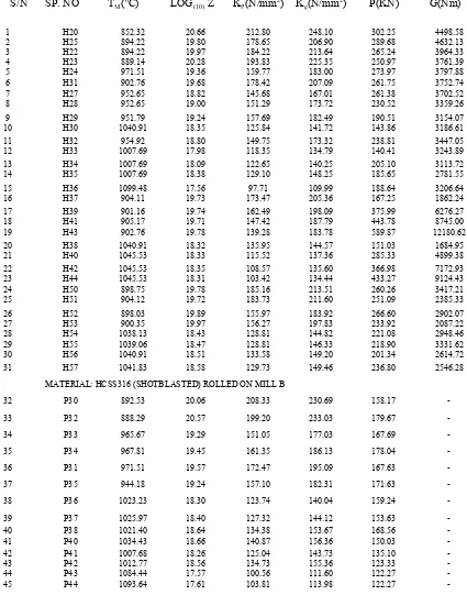
TABLE 1: VALUES OF YIELD STRESSES, LOADS AND TORQUE OBTANED USING HRBFAND MEAN TEMPERATURE BY ROOT MEAN SQUARE METHOD
S/N SP. NO TM(0C) LOG(10) Z
KP(N/mm2)
Kg(N/mm2) P(KN) G(Nm)
1 H20 852.32 20.66 212.80 248.10 302.25 4498.58 2 H25 894.22 19.80 178.65 206.90 289.68 4632.13 3 H22 894.22 19.97 184.22 213.64 265.24 3964.33 4 H23 889.14 20.28 193.83 225.35 250.97 3761.39 5 H24 971.51 19.36 159.77 183.00 273.97 3797.88 6 H31 902.76 19.68 178.42 207.09 261.75 3752.74 7 H27 952.65 18.82 145.68 167.01 261.38 3702.52 8 H28 952.65 19.00 151.29 173.72 230.52 3359.26 9 H29 951.79 19.24 157.69 182.49 190.51 3154.07 10 H30 1040.91 18.35 125.84 141.72 143.86 3186.61 11 H32 954.92 18.80 149.75 173.32 238.81 3447.05 12 H33 1007.69 17.98 118.35 134.79 140.41 3243.89 13 H34 1007.69 18.09 122.65 140.25 205.10 3113.72 14 H35 1007.69 18.38 129.10 148.25 185.65 2781.55 15 H36 1099.48 17.56 97.71 109.99 188.64 3206.64 16 H37 904.11 19.73 173.47 205.36 167.25 1862.24 17 H39 901.16 19.74 162.49 198.09 375.99 6276.27 18 H41 905.17 19.71 147.42 187.79 443.78 8745.00 19 H43 902.76 19.78 139.28 183.78 589.87 12180.62 20 H38 1040.91 18.32 135.95 144.57 151.03 1684.95 21 H40 1045.53 18.33 115.52 137.36 285.33 4899.38 22 H42 1045.53 18.35 108.57 135.60 366.98 7172.93 23 H44 1045.53 18.31 103.42 134.44 433.27 9124.43 24 H50 898.75 19.78 185.16 213.51 260.26 3417.21 25 H51 904.12 19.72 183.73 211.60 251.09 2385.33 26 H52 898.03 19.89 155.97 183.92 266.60 2902.07 27 H53 900.35 19.97 156.27 197.83 233.92 2087.22 28 H54 1038.13 18.43 128.81 144.82 221.08 2948.46 29 H55 1039.06 18.47 128.81 146.33 218.90 3331.62 30 H56 1040.91 18.51 133.58 149.20 201.34 2614.72 31 H57 1041.83 18.58 129.73 149.46 236.80 2546.28
MATERIAL: HCSS316 (SHOTBLASTED) ROLLED ON MILL B
32 P30 892.53 20.06 208.33 230.69 158.17 -
33 P32 888.29 20.57 199.20 233.03 179.67 -
34 P33 965.67 19.29 151.05 177.03 167.69 -
35 P34 967.81 19.45 161.35 186.13 178.04 -
36 P31 971.51 19.57 172.47 195.09 167.63 -
37 P35 944.18 19.24 157.10 182.31 171.63 -
38 P36 1023.23 18.30 123.74 140.04 159.24 -
39 P37 1025.97 18.40 127.32 144.12 153.63 -
40 P38 1021.40 18.64 134.38 153.67 168.56 -
41 P40 1034.43 18.66 140.87 156.36 150.03 -
42 P41 1007.68 18.26 125.04 143.73 135.10 -
43 P42 1012.77 18.56 134.73 155.36 123.33 -
44 P43 1084.44 17.57 100.56 111.60 122.27 -
TABLE 2: A COMPARISON BETWEEN EXPERIMENTAL AND CALCULATED ROLLING LOAD USING HOT ROLLING BLAND AND FORD’S THEORY BASED ON RMS MEAN ROLLING TEMPERATURE.
SPEC. EXPERIMENTAL CALCULATED PERCENTAGE
NO ROLLING LOAD ROLLING LOAD ERROR (%)
[KN] [KN]
AIYEDUN]
MATERIAL: HCSS316 (SHOTBLASTED) ROLLED ON MILL A
1 H20 300.60 302.25 -0.55
2 H25 271.48 289.68 -6.70
3 H22 251.18 265.24 -5.60
4 H23 237.24 250.97 -5.79
5 H24 241.03 259.38 -7.61
6 H31 257.34 261.75 -1.71
7 H27 232.46 261.38 -12.44
8 H28 227.09 230.52 -1.51
9 H29 197.98 190.51 3.78
10 H30 199.69 143.86 12.22
11 H32 251.18 238.81 4.93
12 H33 215.65 208.55 3.29
13 H34 185.22 205.10 -10.73
14 H35 167.48 185.65 -10.85
15 H36 178.84 188.64 -5.48
16 H37 159.94 167.25 -4.57
17 H39 345.18 375.99 -8.93
18 H41 455.54 443.78 2.58
19 H43 549.43 589.87 -7.36
20 H38 138.28 151.03 -9.22
21 H40 261.33 285.33 -9.18
22 H42 329.00 366.98 -11.54
23 H44 329.49 433.27 -10.09
24 H50 263.90 260.26 1.38
25 H51 225.90 251.09 -11.15
26 H52 265.19 266.60 -0.53
27 H53 208.00 233.92 -12.46
28 H54 202.96 221.08 -8.93
29 H55 209.33 218.90 -4.57
30 H56 215.65 201.34 6.64
31 H57 230.99 236.80 -2.52
MATERIAL: HCSS316 (SHOTBLASTED) ROLLED ON MILL B
32 P30 160.34 158.17 1.35
33 P32 180.43 179.67 0.42
34 P33 188.56 167.69 11.07
35 P34 187.03 178.04 4.81
36 P31 173.36 167.63 3.30
37 P35 157.13 171.63 -9.23
38 P36 149.03 159.24 -6.85
39 P37 149.86 153.63 -2.52
40 P38 169.59 168.56 0.61
42 P41 133.08 135.10 -1.52
43 P42 125.84 123.33 1.99
44 P43 121.61 122.27 -0.55
45 P44 128.61 122.27 4.93
46 P45 135.26 134.49 0.57
TABLE 3: A COMPARISON BETWEEN EXPERIMENTAL AND CALCULATED ROLLING TORQUE USING HOT ROLLING BLAND AND FORD’S THEORY BASED ON RMS MEAN ROLLING
TEMPERATURE.
SPEC EXPT. ROLL'G CALC.ROLL'G %ERROR
NO TORQUE TORQUE
[Nm] [Nm]
MATERIAL: HCSS316 (SHOTBLASTED) ROLLED ON MILL A
1.00 H20 4474.00 4498.58 -0.55
2.00 H25 3965.50 4632.13 -16.81
3.00 H22 3830.00 3964.33 -3.51
4.00 H23 3525.00 3761.39 -6.71
5.00 H24 3728.00 3797.88 -1.87
6.00 H31 4270.60 3752.74 12.13
7.00 H27 3965.60 3702.52 6.63
8.00 H28 3694.40 3359.26 9.07
9.00 H29 3287.70 3154.07 4.06
10.00 H30 3321.60 3186.61 4.06
11.00 H32 4067.20 3447.05 15.25
12.00 H33 3660.50 3243.89 11.38
13.00 H34 3186.00 3113.72 2.27
14.00 H35 2860.60 2781.55 2.76
15.00 H36 3219.90 3206.64 0.41
16.00 H37 2101.40 1862.24 11.38
17.00 H39 5761.90 6276.27 -8.93
18.00 H41 7693.90 8745.00 -13.66
19.00 H43 9829.20 11180.62 -13.75
20.00 H38 1965.80 1684.95 14.29
21.00 H40 4779.00 4899.38 -2.52
22.00 H42 6541.50 7172.93 -9.65
23.00 H44 8202.30 9124.43 -11.24
24.00 H50 3660.50 3417.21 6.65
25.00 H51 2281.00 2385.33 -4.57
26.00 H52 2914.90 2902.07 0.44
27.00 H53 1796.40 2087.22 -16.19
28.00 H54 3084.00 2948.46 4.39
29.00 H55 3186.00 3331.62 -4.57
30.00 H56 2745.40 2614.72 4.76
TABLE 4: A COMPARISON BASED ON THE RATIO OF EXPERIMENTAL TO CALCULATED ROLLING LOAD BETWEEN REVERSE SANDWICH MODEL [SHOBOWALE], RSM - HRBF [ALAMU] AND HRBF
BASED ON RMS MEAN ROLLING TEMPERATURE.
SPEC. LOG(10)Z RATIO OF RATIO OF RATIO OF
NO EXP/CAL. LOAD EXP/CAL. LOAD EXP/CAL. LOAD
[SHOBOWALE] [ALAMU] HRBF
[BASED ON RMS TEMP.] MATERIAL: HCSS316 (SHOTBLASTED) ROLLED ON MILL A
H20 20.66 1.20 1.03 1.02
H25 19.80 1.18 0.98 1.00
H22 19.97 1.16 0.99 0.98
H23 20.28 1.10 0.99 0.95
H24 19.36 1.08 0.92 0.92
H31 19.68 1.20 1.10 1.08
H27 18.82 1.15 1.03 1.04
H28 19.00 1.12 1.03 1.04
H29 19.24 1.10 0.95 0.99
H30 18.35 1.22 0.94 0.93
H32 18.80 1.16 1.10 1.05
H33 17.98 1.14 1.04 1.03
H34 18.09 1.04 0.94 0.90
H35 18.38 1.13 0.94 0.90
H36 17.56 1.22 0.99 0.95
MATERIAL: HCSS316 (SHOTBLASTED) ROLLED ON MILL B
P30 20.06 1.14 1.06 1.01
P32 20.57 1.12 1.05 1.10
P33 19.29 1.22 1.12 1.08
P34 19.45 1.27 1.05 1.10
P31 19.57 1.30 1.03 1.03
P35 19.24 1.10 0.95 0.95
P36 18.30 1.18 0.98 0.94
P37 18.40 1.14 1.02 0.98
P38 18.64 1.30 1.05 1.00
P40 18.66 1.43 1.02 0.98
P41 18.26 1.20 1.03 0.99
P42 18.56 1.25 1.05 1.02
P43 17.57 1.16 1.04 0.99
P44 17.61 1.38 1.07 1.02
P45 17.70 1.27 1.05 1.01
P55 19.31 1.35 1.16 1.11
P48 19.45 1.20 1.03 0.98
P50 19.38 1.10 0.98 0.94
P47 18.65 1.40 1.22 1.01
P49 18.82 1.15 0.96 1.21
P51 18.69 1.20 0.00 0.96
TABLE 5: A COMPARISON BASED ON THE RATIO OF EXPERIMENTAL TO CALCULATED ROLLING TORQUE BETWEEN REVERSE SANDWICH MODEL [SHOBOWALE], RSM-HRBF [ALAMU] AND HRBF
BASED ON RMS MEAN ROLLING TEMPERATURE
SPEC. LOG Z RATIO OF RATIO OF RATIO OF
NO EXP/CAL. TORQ. EXP/CAL. TORQ. EXP/CAL. TORQ.
[SHOBOWALE] [ALAMU] HRBF
[BASED ON RMS TEMP.] MATERIAL: HCSS316 (SHOTBLASTED) ROLLED ON MILL A
H20 20.66 1.20 1.04 0.99
H25 19.80 1.10 1.01 0.86
H22 19.97 1.23 1.01 0.97
H23 20.28 1.15 0.98 0.94
H24 19.36 1.16 1.02 0.98
H31 19.68 1.30 1.19 1.14
H27 18.82 1.31 1.12 1.07
H28 19.00 1.34 1.15 1.10
H29 19.24 1.28 1.09 1.04
H30 18.35 1.30 1.09 1.04
H32 18.80 1.36 1.23 1.18
H33 17.98 1.30 1.18 1.13
H34 18.09 1.20 1.07 1.02
H35 18.38 1.20 1.07 1.03
H36 17.56 1.17 1.05 1.00
Fig.3.1: Dependence of Ratio of Experimental Load to Calculated Load on Zener-Hollomon Parameter for HCSS316 Rolled on Mill A at r = 10%, Different Tf , Varying strain Rates (Based on RMS Mean Rolling
Temperature)
0.86 0.91 0.96 1.01 1.06
17.00 17.50 18.00 18.50 19.00 19.50 20.00 20.50 21.00
[P
exp
/P
cal
]
LOG (10)Z
H32-H36, Tf=1200 C H31-H30, Tf=1125 C H20-H24,Tf=1050 C
1
3
4 2
5 5
4 2
3
1
1
2
3
4 5
Fig.3.2: Dpendence of Ratio of Experimental Torque to Calculated Torque on Zener-Hollomon Parameter for HCSS316 Rolled on Mill A at r=10%, Different Tf, Varying Strain Rates (Based on RMS Mean Rolling
Temperature)
Fig.3.3: Dependence of Ratio of Experimental Load to Calculated loadon Zener-Hollomon Parameter for HCSS316 Rolled on Mill B at r = 10%, Different Tf, Varying Strain Rates ( Based on RMS Mean Rolling
Temperature)
17.00 17.50 18.00 18.50 19.00 19.50 20.00 20.50 21.00
[G
H32-H36, Tf=1200 C H31-H30, Tf=1125 C H20-H24, Tf=1050 C
ε1˂ε2˂ε3˂ε4˂ε5
17.00 17.50 18.00 18.50 19.00 19.50 20.00 20.50 21.00
Fig.3.4: Dependence of Ratio of Experimental Load to Calculated Load on Zenner-Hollomon Parameter for Different Reductions, Hot Rolling on Mill A & B at Low & High Strain Rates, Tf = 11250C (Based on RMS Mean
Rolling Temperature)
Fig.3.5: Dependence of Experimental Torque to Calculated Torque on Zener-Holllomon Parameter for Different Reduction, Hot Rolling on Mill A and Mill B at Low & High Strain Rates, Tf = 1125
0
18.20 18.40 18.60 18.80 19.00 19.20 19.40 19.60 19.80
Fig. 3.6: Dependence of Ratio of Experimental Load to Calculated Load on Zener-Hollomon Parameter for Rolling of Different Geometry (W/H0) at R = 10%, Tf = 11250C at Fast Slow Strain Rates on Mill A & Mill B
(Based on RMS Mean Rolling Temperature)
Fig.3.7: Dependence of Ratio of Experimental Torque to Calculated Torque on Zener-Hollmon Parameter for Different Geometry (W/H0) Hot Rolled on Milll A & Mill B at Low & High Strain Rates, Tf = 1125
18.40 18.60 18.80 19.00 19.20 19.40 19.60 19.80 20.00
Fig.3.8: A Comparison among RSM [SHOBOWALE], RSM- HRBF[ALAMU] & HRBF Theory (RMS Mean Rolling Tp.) for Dependence of Ratio of Exptl. to Calctd. Load on Zener-Hollomon Parameter for HCSS316
Rolled on Mill A at R = 10%, diff.TF & Strain Rates.
Fig.3.9: A Comparison among RSM [Shobowale], RSM-HRBF Theory [Alamu] & HRBF (based on RMS Mean Rolling Temp.) for Dependenceof Ratio of Exptl. Torqueto Calctd.Torque on Zener- Hollomon Parameter for
HCSS316 rolled on Mill A at R = 10%, diff. TF and Strain Rates
17.4 17.9 18.4 18.9 19.4 19.9 20.4
[
17.00 17.50 18.00 18.50 19.00 19.50 20.00 20.50 21.00
Fig. 3.10: A Comparison among RSM [Shobowale], RSM-HRBF Theory[Alamu]& HRBF (based on RMS Mean Rolling Temp.) for Dependence of Ratio of Exptl. Load to Calctd. Load on Zener- Hollomon Parameter for
HCSS316 rolled on Mill B at R = 10%, diff.TF and Strain Rates.
REFERENCES
[1] AFONJA, A.A. and SANSOME, D.H. (1973), “A Theoretical Analysis of the Sandwich
Rolling Process” Int. J. Mech. Sci., Vol. 15, pp. 1 – 14
[2] AIYEDUN, P.O. (1984), “A Study of Loads and Torques for Light Reduction in Hot Flat
Rolling at Low Strain Rates” Ph.D. Thesis, University of Sheffield.
[3] AIYEDUN, P.O. (1986), “Hot Flat Rolling Simulation by Use of the Bland and Ford’s Cold
Rolling Theory for HCCSS316 at Low Reduction and Low Strain Rates”, Proc, Int. AMSE
Conf., Vol. 3, pp. 14 – 36.
[4] AIYEDUN, P.O., SPARLING, L.G.M. and SELLARS, C. M., (1997), “Temperature Change
in Hot Flat Rolling of Steels at low Strain Rates and Low Reduction”. Pro. Instn. Mech.
Engrs. Vol. 211, Part B, pp.261-254.
[5] AIYEDUN, P.O. (1999), “Yield Stress Variation across Thickness for Steel (HC SS316)
Specimen hot rolled at Low Reduction and Low Strain Rates”. NSE Technical Transactions,
Vol. 34, pp. 46 - 70
[6] AIYEDUN, P.O. and ALIU, S. A (2009), “Rolling Temperature for Steel Hot Flat rolled at
Low Strain Rates”, Advanced Materials Research, Vol. 62-64, pp. 317-323.
[7] ALAMU, O.J. (2001), “Integration of the Reverse Sandwich Model into the Hot Rolling
Bland and Ford’s Theory (HRBF) of Load and Torque Calculation”, MSc. Thesis, University
of Ibadan.
[8] ALAMU, O.J. and AIYEDUN, P.O. (2003) “A Comparison of Temperature Gradient in Hot
Rolling at Low and High Strain Rates”. J. Sci. Engr. Tech., 10(1): 4644 – 4654.
[9] FARAG, M.M. and SELLARS, C.M. (1998), “Hot Working and Forming Processes”. Proc., Metals Society Conference, Sheffield.
17.00 17.50 18.00 18.50 19.00 19.50 20.00 20.50 21.00
[PEX P41-P45, TF = 1200 C [SHOBOWALE]
[10] LENARD, J.G. (1980), “Roll Deformation in Cold Strip Rolling’’ Journal of Engineering
Materials and Technology”, ASME Vol. 102, pp. 382 – 383.
[11] SADIQ, T.O. (2012), “Calculated Rolling Load and Torque for Hot Flat Rolling of Hcss316
at Low Strain Rates based on Better Mean Rolling Temperature”. MSc. Thesis, University of
Ibadan.
[12] SELLARS, C.M. (1981), “Les Traitments Thermomecaniques”, 24eme Colloque de Metallurgie, Institut National des Sciences et Technique Nucleaires, Sanclay, pp. 111 - 120. [13] SHOBOWALE, B. (1998), “The Reverse Sandwich Effect in HC SS316 Hot Flat Rolled at


![Fig. 3.10: A Comparison among RSM [Shobowale], RSM-HRBF Theory[Alamu]& HRBF (based on RMS Mean Rolling Temp.) for Dependence of Ratio of Exptl](https://thumb-ap.123doks.com/thumbv2/123dok/3879905.1847635/18.595.58.536.69.357/comparison-shobowale-theory-alamu-rolling-dependence-ratio-exptl.webp)
