ISSN: 1532-5008 print / 1532-5016 online DOI: 10.1080/15325008.2014.903536
Design and Implementation of a Dynamic Evolution
Controller for Single-phase Inverters with Large
Load Changes
Ehsan Najafi,
1Abdul Halim Mohamed Yatim,
2and Ahmad Saudi Samosir
31Faculty of Electrical and Computer Engineering, Qom University of Technology, Qom, Iran 2Faculty of Electrical Engineering, Universiti Teknologi Malaysia, Malaysia
3Department of Electrical Engineering, Lampung University, Bandar Lampung, Indonesia
CONTENTS
1. Introduction 2. DEC
3. Simulation Results 4. Experimental Results 5. Conclusion
References
Keywords: dynamic evolution control, single-phase inverter, inverter control, load change, power quality, power electronics, harmonic Received 10 January 2013; accepted 8 March 2014
Address correspondence to Ehsan Najafi, Faculty of Electrical and Computer Engineering, Qom University of Technology, Qom, Iran, 1519-37195. E-mail: [email protected]
Color versions of one or more of the figures in the article can be found online at www.tandfonline.com/uemp.
Abstract—A new controller is developed for a single-phase inverter based on the dynamic evolution control method. The non-linear model equations and algorithm of the approach is derived and presented. The simulation is conducted based on the proposed method by MAT-LAB/Simulink to test the performance of the controller for large load variations. The system was also tested experimentally to show the feasibility of the proposed method applied to a single-phase inverter. Results show that the proposed approach is suitable for applications with large load variations. Practical results show that the controller can successfully handle a 40 times load change in less than 2 ms. It also has good output in the harmonic spectrum compared with the IEEE 519 harmonic standard during no-load and full-load conditions.
1. INTRODUCTION
Inverters are the most important components for many power conversion applications, such as the uninterruptible power sup-ply (UPS), power quality devices, such as a unified power quality conditioner [1], motor control drives, induction heat-ing, and renewable energy systems [2–5]. The main feature of a well-designed inverter is its ability to provide high-quality and stable AC voltage regardless of the output load. One of the major challenges ahead of the converters is the load change. New electric devices need different power levels at different times, and the inverter should have the ability to recover as quickly as possible from transient conditions caused by load changes [6].
In recent years, various instantaneous feedback control methods on a linear model have been proposed [6–9]. Nor-mally when designing controllers using the conventional linear model control theory, such as proportional integrator (PI) and proportional integral derivative (PID) controllers, small-signal linear approximations are applied to the non-linear system. This approach enables the designer to implement a simple lin-ear controller to a system. However, the main disadvantage of
been proposed for power inverter applications. Since power inverters are non-linear time-varying systems, the design of suitable controllers requires consideration of the non-linearity and time-varying properties of the inverter system. An in-verter deals with many uncertainties and variations, such as system parameter variations, non-linearity, load disturbance, etc. Therefore, conventional linear methods (such as PI con-trollers) are not suitable for this purpose, especially in extreme load changes. Moreover, these controllers usually need a pulse width modulation (PWM) controller to drive the semiconduc-tor switches, which adds to the complexities of the approaches [11].
A well-known method to control inverters is the dq method. This approach transforms variable AC line values to fixed quantities. However, this method is basically introduced for three-phase systems and needs modifications for single-phase applications. To adapt this method for single-phase systems, measured voltage and current should be shifted by a quarter-line cycle; this needs exact frequency calculations, especially during load changes. This shows that this method is quite com-plex especially for implantation purposes. To avoid problems with this method during load changes, the concept of fictive axis emulation is introduced, adding to the complexity of the approach [12]. To overcome the restrictions of linear control methods for inverter control, researchers have proposed sev-eral non-linear control methods. The fuzzy control method a well-known method to overcome linear method shortcomings [8, 9]. Although it is more robust and does not need a system mathematical model, it is highly based on experience, and its rules and structure are mostly designed by trial and error [10]. It also needs extensive and complex calculations to determine the suitable output.
Another non-linear control method used for inverter appli-cation is predictive model control. However, this method re-quires an observer to improve the inverter performance, which adds to the complexities of the method. To tune the observer speed, accurate pole placement should be done, and this re-quires additional knowledge about system performance [13].
In this article, a new approach for an inverter controller based on the dynamic evolution control (DEC) theory [14–17] is proposed and implemented. DEC exploits the non-linearity and time-varying properties of the system to make it a
su-in such variable switchsu-ing frequency methods as the hystere-sis method. Although this method is implemented on DC-DC converters, it has not been tested on inverter applications that need an alternative reference.
Sliding-mode control seems to be suitable for inverter con-trol applications [18–20]. However, its coefficients need to be updated continuously to improve its tracking capability. Therefore, it needs extensive calculations [21] or some form of intelligent control or fuzzy logic to determine the continu-ously changing coefficients. It also suffers from a chattering problem that leads to variable and high-frequency switching in the converter [22].
In comparison with other new control methods, the pro-posed method has better results in terms of power quality and a simpler structure for implementation; therefore, it does not need fast and high-speed processors, such as field pro-grammable gate array (FPGA). FPGA-based controllers suffer from a long prototyping development time and troubleshoot-ing complexities. When good control performance is required, coding must be done in hardware description language (HDL), leading to substantial efforts during the design of the hardware architecture [23]. In [24], multi-dimensional calculations were carried out by FPGA, which made it more complex compared to conventional space vector modulation (SVM) control [12, 25]. This method also generates sideband harmonics that can interfere in control loops and are difficult to remove by filters [26]. It therefore needs higher-order shaping filters that add to the complexities of the approach [24].
The proposed approach also does not need to calculate the pole and zeros of the system to enhance the performance of the controller [27]. This method has also wide range of stability as experimentally proven and does not suffer from system parameter change instability [28].
2. DEC
2.1. Principle of DEC
FIGURE 1.Dynamic evolution path.
The principle of DEC is also based on reduction of the dif-ference (error) between redif-ference and actual operating points. This difference is that the error state is forced to zero by following a specified path; therefore, the error state rapidly decreases to zero after a disturbance.
2.2. Evolution Path and DEC
The main objective of the DEC method is to control the dy-namic characteristic of the system so that the state error (Y) becomes zero (Y =0); therefore, an evolution path for state error is adopted to make it zero after several cycles.
The following exponential function is selected for the evo-lution path of the state error in this research due to its fast response and simple structure:
Y =Ce−mt, (1)
whereCis the initial value of error state (Y), andmis a coef-ficient for the decrease rate of the error state. Asmbecomes larger, the error decreases faster according to the exponential function expression.
The evolution path is shown in Figure 1. In this exponential function, the value ofY is reduced exponentially to zero as a function of time. The reduction speed of the state error (Y) is proportional tom.Cis the initial value of state error (Y0), and
the following equation is obtained:
Y =Y0e−mt. (2)
The derivative ofYis found as follows:
dY
dt = −mY0e −mt
. (3)
This equation can be written as follows:
dY
dt = −mY. (4)
Therefore, the state error equation for dynamic evolution is obtained as
dY
dt +mY =0. (5)
In this equation,mis a positive integer specifying the de-crease rate of the state error in DEC.
FIGURE 2.Inverter general schematic diagram.
2.3. Application of DEC on Single-phase Inverter
To apply the proposed control method on an inverter, the state error equation based on inverter parameters should be obtained. Therefore, the controller determines the appropri-ate value for the duty cycle to follow the evolution path and decrease the state error to zero.
The general schematic diagram of a single-phase inverter is depicted in Figure 2. Operation of the circuit is mainly divided into two states: positive and negative. In the positive state, the output voltage has positive polarity, and the inverter switches between zero and DC voltage (VDC). On the other
hand, the output voltage polarity toggles between –VDC and
zero to generate negative polarity in the negative state. In the positive state, the circuit operation is also divided into two cases. In the first case, S1 and S2 are on while other switches are off and DC voltage is applied to the output load. The circuit characteristic equation is as follows:
Vdc=L
diL
dt +V0. (6)
In the second case, S1 and S2 are off to apply zero voltage to the output load. The circuit characteristic equation is as follows:
0=LdiL
dt +V0. (7)
dt dt
In a switching period, the off time (toff) and on time (ton)
generate the overall switching period (T) and can therefore be replaced as follows:
To f f =T −Ton. (11)
Duty cycle (α) is also relevant to on time (ton) as follows:
∝= ton
T . (12)
Replacing Eq. (11) into Eq. (10) and dividing the whole equation by the switching period (T), the final characteristic equation for state 1 is obtained:
V0=∝.VDC−LdiL
dt . (13)
The same procedure can be followed to determine the char-acteristic equation for state 2. The final charchar-acteristic equation for state 2 is as follows:
V0= − ∝.VDC−LdiL
dt . (14)
To apply DEC on the inverter as in Eq. (1), the state error function is defined as follows:
Y =kVerr, (15)
where k is a positive coefficient and is considered a small fractional number (such as 0.01). Verr is defined as voltage
error as follows:
Verr =Vr e f −V0. (16)
The derivative ofY is found as follows:
dY dt =k
d Verr
dt . (17)
Replacing Eqs. (17) and (15) into Eq. (5) gives
kd Verr
dt +m.k.Verr =0. (18)
Equation (18) can be rearranged as follows:
kd Verr Therefore, the duty cycle is obtained from Eq. (22) as fol-lows for state 1: The same procedure is true for state 2, which leads to
∝= − Equations (23) and (24) are used to calculate the appropriate duty cycle for the inverter. Therefore, output voltage deviation from the reference in inverter (error state) will follow the evolution path to reduce the error state to zero and reach its target reference.kis a scaling factor to downscale the actual values used in the calculations, and in this work,kis set at 0.1.mfunctions as the error convergence, and if it is set high, the errors converge rapidly, thus having good response to load changes. However, if it is set too high, overshoots in the error may occur due to the overflow in the DSP registers. In this work,mis iteratively selected to ensure good response without overshooting the error.
In comparison with [30], this controller presents better re-sults in terms of the harmonic spectrum due to its output switching levels. The proposed controller switches between
VDCand zero in the positive cycle and –VDCand zero in the
negative cycle (the output voltage change is equal toVDCin
both cycles), while the controller in [30] switches between –VDCandVDC(equal to 2.VDC), which is double the amount
of change in the proposed controller. Therefore, the voltage stress in the output load for the proposed method is half that of [30]. This will also decrease the sensitivity of the out-put voltage to duty cycle in the proposed controller. It means that with a change in duty cycle, in the proposed method, the output change is smaller compared to [30] due to the smaller output voltage changes. This will improve the quality of the output voltage.
FIGURE 3.General block diagram for simulation.
This requirement creates a small limitation on the control system since it is sometimes difficult to obtain the exact value ofL. In practice, small changes in inductor value do not affect the overall controller performance.
3. SIMULATION RESULTS
Simulation is done by MATLAB/Simulink (The MathWorks, Natick, Massachusetts, USA) to verify the controller perfor-mance. Figure 3 shows the simulation model. In this model, a single-phase inverter is controlled by the proposed method.
The most important capability of DEC is its ability to re-spond effectively under a step load change condition. There-fore, a load change is imposed to the inverter to investigate its dynamic performance.
Circuit parameters for simulation are also mentioned in Table 1. The output load RMS current is 28 mA in steady
Circuit parameter Value
Input DC voltage 60 V
Peak output voltage 40 V No load resistance 1 Kohm Load change resistance 22 ohm Switching frequency 20 kHz
Line frequency 50 Hz
Output inductor 10 mH
Output capacitor 47µF
k 0.01
m 2000
TABLE 1.Circuit parameters for simulation
FIGURE 4.Error during load change for differentm(m=
2000,m=20,000).
state; it then suddenly changes to 1.28 A, which is a large load change, to show the capability of controller to overcome large load conditions.
To show the effect ofmon the results, the error voltage (Verr) is depicted in Figure 4 during load change for different
values ofm. Asmincreases from 2000 to 20,000, oscillation and overshoot occur in the error.
The inverter output voltage and current together with the reference voltage are shown in Figure 5. As shown in Figure 5, initially, the inverter operates in almost no load. A large load change occurs att=55 ms. The inverter output voltage follows the reference in all instances. However, there is a small output voltage drop during the load change that lasts less than 2 ms. This voltage drop is approximately 25% and is small compared to the large amount of load change. The proposed controller is able to respond fast and is stable enough to handle large load changes.
The next section presents the experimental results for the controller to illustrate the practical capability of the controller. A prototype is built based on the simulation results and with the same circuit parameters.
4. EXPERIMENTAL RESULTS
A single-phase inverter prototype is built based on the simula-tion results. This prototype is controlled by a dSPACE (ds1104)
FIGURE 6.Experimental results of the proposed controller during no-load to full-load change, inverter output current (0.5 A/div), inverter output voltage (20 V/div), and inverter refer-ence voltage (20 V/div).
DSP (dSPACE GmbH, Paderborn, Germany) that is compati-ble with MATLAB.
The control method is developed and simulated in a MAT-LAB/Simulink environment. The same blocks used in this environment are adopted for the DSP. Then it is compiled and downloaded into the DSP to control the inverter. The DSP receives the value of inverter voltage and current and gen-erates the appropriate duty cycle according to the developed dynamic evaluation control. An isolated voltage transducer (LV25-P, LEM Company, Kuala Lumpur, Malaysia) is used as a voltage sensor in this experiment, and the current is measured through a Hall effect ACS712 sensor (Allegro Microsystems Company, Penang, Malaysia).
FIGURE 7.Dynamic results of the proposed controller during full-load to no-load change, reference voltage, output voltage and current, inverter output current (1 A/div), inverter output voltage (20 V/div), and inverter reference voltage (20 V/div).
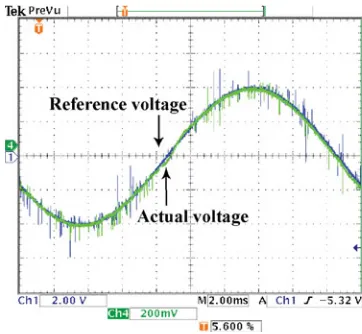
FIGURE 8.Experimental results for static performance of proposed controller during full load, actual voltage, and refer-ence voltage (10 V/div).
The experimental circuit parameters are the same as in Table 1. The almost no-load power was only 0.9 W, measured using a power analyzer. To investigate the dynamic perfor-mance of the proposed controller, a large load change is im-posed on the inverter. In the experiment, the load is changed from 0.9 to 36.1 W, which is about 40 times larger.
Figure 6 experimentally demonstrates the dynamic perfor-mance of the controller during load changes. The controller can successfully respond to large changes in the output voltage and follow the reference rapidly. It illustrates that this major load change generates approximately a 30% voltage drop and lasts less than 2 ms. The capability of the controller to over-come large signal disturbances without instability problems is also shown in this figure.
Figure 7 shows the capability of the controller for a step-down load. The voltage is controlled according to the reference value with only a little disturbance. Unlike the approach in [31], the proposed approach does not have overshoot during a full-load to no-load change. The load current does not drop sharply to a no-load current due to the effect of the filter inductor.
Figure 8 exhibits experimental results of inverter output voltage together with the reference that is generated by a DSP built in a digital-to-analog converter.
As discussed earlier, the controller presents good output power quality that is proven by the experimental results.
Figure 9 illustrates inverter output voltage and current dur-ing no-load conditions. The voltage total harmonic distortion (THD) was 0.88% measured using a power analyzer.
FIGURE 9.Inverter output voltage (20 V/div) and current (50 mA/div) during no-load conditions.
FIGURE 10.Inverter output voltage (20 V/div) and current (2 A/div) during full-load conditions.
FIGURE 11. Harmonic spectrum of output voltage during full-load conditions, percentage of each harmonic order com-pared to fundamental harmonic order (50 Hz).
FIGURE 12.Experimental results for static performance of proposed controller with reactive load, inverter output voltage (20 V/div), and current (1 A/div).
The harmonic spectrum in this condition is also depicted in Figure 11, which verifies the good output voltage quality of the controller due to the selected output voltage levels.
Finally, the performance of the controller for a reactive load is also investigated, as shown in Figure 12. A 90-mH inductor is placed in series with a light resistive load to observe the inverter output voltage and current for reactive loads. The result in Figure 12 shows that the controller can work successfully for both resistive and inductive loads.
5. CONCLUSION
This article presents a new controller based on the DEC method for inverter applications. DEC for single-phase ap-plications proved to be effective and fast, especially for large load changes.
A simulation is done based on the derived mathematical model for the controller. Then an experimental setup is devel-oped to show the feasibility of the control method applied to inverters. The practical results show that the controller is capa-ble of responding rapidly to the load change with a small dip lasting for 2 ms. The output power quality has low harmonics and is within the standard limits.
REFERENCES
[1] Pal, Y., Swarup, A., and Singh, B., “Flexible control of single-phase unified power quality conditioner using frequency-domain approach,” Elect. Power Compon. Syst., Vol. 41, pp. 401–412, 2013.
Syst., Vol. 41, pp. 31–46, 2012.
[6] Ayob, S. M., Azli, N. A., and Salam, Z., “Single input PI-fuzzy controller for single phase inverter system,”IREE, Vol. 3, pp. 418–425, 2008.
[7] Habetler, T. G., and Harley, R. G., “Power electronic con-verter and system control,”Proc. IEEE, Vol. 89, pp. 913–925, 2001.
[8] Ying-Yu, T., and Shih-Liang, J., “Full control of a PWM DC-AC converter for AC voltage regulation,”IEEE Trans. Aerospace Electron. Syst., Vol. 34, pp. 1218–1226, 1998.
[9] Tsang-Li, T., and Jian-Shiang, C., “UPS inverter design us-ing discrete-time slidus-ing-mode control scheme,”IEEE Trans. Indust. Electron., Vol. 49, pp. 67–75, 2002.
[10] Raviraj, V. S. C., and Sen, P. C., “Comparative study of proportional-integral, sliding mode, and fuzzy logic controllers for power converters,” IEEE Trans. Indust. Appl., Vol. 33, pp. 518–524, 1997.
[11] Sotoodeh, P., and Miller, R. D., “A novel single-phase inverter with distribution static compensator capability for wind appli-cations,”Elect. Power Compon. Syst., Vol. 41, pp. 1294–1310, 2013.
[12] Ninad, N. A., and Lopes, L. A. C., “A vector-controlled single-phase voltage source inverter based grid interface suitable for variable frequency operation in autonomous microgrids,”Elect. Power Compon. Syst., Vol. 40, pp. 1266–1284, 2012.
[13] Cortes, P., Ortiz, G., Yuz, J. I., Rodrigues, J., Vazquaz, and Franquelo, L. G., “Model predictive control of an inverter with output LC filter for UPS applications,” IEEE Trans. Indust. Electron., Vol. 56, pp. 1875–1883, 2009.
[14] Samosir, A. H. M. Y. A. S., “Implementation of new control method based on dynamic evolution control for DC-DC power converter,”IREE, Vol. 4, pp. 1–6, 2009.
[15] Samosir, A. S., and Yatim, A. H. M., “Implementation of new control method based on dynamic evolution control with lin-ear evolution path for boost DC-DC converter,” IEEE 2nd International Power and Energy Conference (PECon 2008), pp. 213–218, Johor Bahru, Malaysia, 1–3 December 2008. [16] Samosir, A. S., and Yatim, A., “Dynamic evolution control
of bidirectional DC-DC converter for interfacing ultracapacitor energy storage to fuel cell electric vehicle system,”Australasian Universities Power Engineering Conference (AUPEC ‘08), pp. 1–6, Australia, 14–17 December 2008.
[17] Samosir, A. S., and Yatim, A. H. M., “Implementation of dynamic evolution control of bidirectional DC-DC converter for interfacing ultracapacitor energy storage to fuel-cell sys-tem,”IEEE Trans. Indust. Electron., Vol. 57, pp. 3468–3473, 2010.
[18] Sofla, M. A., and Gharehpetian, G. B., “Dynamic performance enhancement of microgrids by advanced sliding mode
con-39, pp. 548–562, 2011.
[21] Komurcugil, H., “Rotating-sliding-line-based sliding-mode control for single-phase UPS inverters,”IEEE Trans. Indust. Electron., Vol. 59, pp. 3719–3726, 2012.
[22] Jiabing, H., Lei, S., Yikang, H., and Zhu, Z. Z., “Direct ac-tive and reacac-tive power regulation of grid-connected DC/AC converters using sliding mode control approach,”IEEE Trans. Power Electron., Vol. 26, pp. 210–222, 2011.
[23] Buccella, C., Cecati, C., and Latafat, H., “Digital control of power converters—a survey,”IEEE Trans. Indust. Informat., Vol. 8, pp. 437–447, 2012.
[24] Jwu-Sheng, H., Keng-Yuan, C., Te-Yang, S., and Chi-Him, T., “Control of voltage source inverter using multidimensional feedback quantization modulator,”IEEE Trans. Indust. Elec-tron., Vol. 58, pp. 3027–3036, 2011.
[25] Sanbo, P., Junmin, P., and Zuohua, T., “A shifted SVPWM method to control DC-link resonant inverters and its FPGA real-ization,”IEEE Trans. Indust. Electron., Vol. 59, pp. 3383–3391, 2012.
[26] Odavic, M., Sumner, M., Zanchetta, P., and Clare, J. C., “A theo-retical analysis of the harmonic content of PWM waveforms for multiple-frequency modulators,”IEEE Trans. Power Electron., Vol. 25, pp. 131–141, 2010.
[27] Turner, R., Walton, S., and Duke, R., “Robust high-performance inverter control using discrete direct-design pole placement,”
IEEE Trans. Indust. Electron., Vol. 58, pp. 348–357, 2011. [28] Yiqiang, C., Mwinyiwiwa, B., Wolanski, Z., and Boon-Teck, O.,
“Regulating and equalizing DC capacitance voltages in multi-level STATCOM,”IEEE Trans. Power Delivery, Vol. 12, pp. 901–907, 1997.
[29] Ogata, K.,Modern Control Engineering: Prentice-Hall, 1997. [30] Samosir, A. S., and Yatim, A. H. M., “Dynamic evolution
controller for single phase inverter application,” IEEE Sym-posium on Industrial Electronics & Applications (ISIEA 2009), pp. 530–535, Kuala Lumpur, Malaysia, 4–6 October 2009. [31] Abrishamifar, A., Ahmad, A. A., and Mohamadian, M., “Fixed
switching frequency sliding mode control for single-phase unipolar inverters,”IEEE Trans. Power Electron., Vol. 27, pp. 2507–2514, 2012.
BIOGRAPHIES
until 2013. He then joined Qom university of technology as an assistant professor. His research interests include power electronics, multilevel inverters, FACTS and power quality.
Abdul Halim Mohamed Yatim received the B.Sc. degree
in electrical and electronic engineering from Portsmouth Polytechnic, Portsmouth, U.K., in 1981, and the M.Sc. and Ph.D.degrees in power electronics from Bradford University, Bradford, U.K., in 1984 and 1990, respectively. Since 1982, he has been a member of the faculty at the Universiti Teknologi Malaysia, Johor, Malaysia. He was a Commonwealth Fel-low during 1994–1995 at Heriot-Watt University, Edinburgh, U.K., and a Visiting Scholar at the Virginia Power Electronics Center, Virginia Polytechnic Institute and State University, Blacksburg, in 1993. He is a Fellow of the Institution of Engineers Malaysia and a Registered Professional Engineer with the Malaysian Board of Engineers. He is also the founder and the first Chapter Chair of the Malaysian Section of the IEEE Industrial Electronics/Industry Applications/Power
Electronics Joint Societies. His research interests include power electronics, renewable energy, electrical drives, mul-tilevel inverters and power quality.