Experimental Study on Shear Capacity of RC Beams Strengthened With
Carbon Fiber Reinforced Polymer
Mandated by ACIi 440
SRI Tudjono
1,a*, HIMAWAN Indarto
1,b, MONICA Devi
1,c1Civil Engineering Department, Diponegoro University, Semarang, Indonesia
a[email protected], b[email protected], c[email protected]
Keywords: Shear Capacity, Shear Reinforcement, Retrofit,CFRP
Abstract. Shear reinforcement for retrofitting a reinforced concrete (RC) beam using unidirectional
Carbon Fiber Reinforced Polymer (CFRP) woven can only be applied on the beam web below the concrete floor slab. Thus, it cannot fully confine like the way stirrups do, in which it will affect the shear capacity. The CFRP can only be ‘n’or ‘u’ shaped, taking into consideration the direction of shear force. Herein, the experimental study of the shear capacity of shear capacity the beam strengthened by FRP is carried out.shear capacity. The beams are RC beams of width 150 mm, height 300 mm, span of 1000 mm, f'c = 26 MPa having 2 bar of 19 mm diameter (fy = 403.65 MPa)
and stirrups 6 mm diameter of 250 mm spacing (fy=375 MPa). The shear capacity measured is then
compared with the shear capacity calculated using ACI 440. The result shows that the shear capacity measured from experiment is greater than the shear capacity calculated by ACI 440. Also, the shear capacity of RC beam with CFRP reinforcement n shape is greater than u shape.
Introduction
Retrofitting may be needed for an existing RC structure when the capacity measured is less than the design capacity. When the problem is its shear capacity, additional shear reinforcement shall be installed to prevent the structure from failing under shear mode. The most common retrofitting method on shear reinforcement of RC beam is by using u shaped of CFRP sheets. It shall however be noted that the shear retrofit using CFRP works as the CFRP provides additional confinement to the concrete in compression, not in tension. Thus, for RC beams located in the area of negative moment, such like the area near beam column joint in RC frames, further study is needed.
Shear and flexural retrofitting using CFRP have been studied by many researchers [1,2] and also coped in ACI 440 code [3]. Namboorimadathil [1] studied shear and flexural strengthening of T beam in the area of negative moment. T beam of 14 ft span, 20 inch depth, 32 inch flange width and 4 inch flange thickness was used. Shear strengthening using 2 layers of u shaped FRP fully wrapped on its longitudinal direction was applied onto T beam. Flexural strengthening using two layers of FRP sheet was installed on the flange of the T beam instead of on top of the T beam to provide the continuity of the strengthening due to the presence of the existing column. Bagio et al. [2] conducted a study on RC beam shear reinforced by CFRP and glass FRP sheet. The experiment was carried out on a beam of 2200 mm span, 350 mm depth and 150 mm width. The u shaped FRP was not fully wrapped onto the beam on its longitudinal direction. The study was conducted in variation of wrapping height, and the presence of FRP anchor. This method is more appropriate for reinforcing the positive moment area. The aforementioned literature review showed a gap to obtain a more appropriate method of shear reinforcement for the negative moment area which will be presented in the following paper.
Methodology
The behaviors of CFRP shear reinforcements in the positive moment and negative moment area are certainly different. Let us now consider the u shaped CFRP. In the positive moment area, the u
shaped CFRP ‘wrap’ a concrete under tension. On the other hand, in the negative moment area the u
shaped CFRP confined a concrete under compression. Under compression, the compressive strength
Applied Mechanics and Materials Submitted: 2015-08-29 ISSN: 1662-7482, Vol. 845, pp 154-157 Revised: 2015-10-11 doi:10.4028/www.scientific.net/AMM.845.154 Accepted: 2015-10-18 © 2016 Trans Tech Publications, Switzerland Online: 2016-07-25
of the confined concrete will increase, leading to the increase of shear capacity of the concrete. This study will examine two methods of strengthening, i.e. u shaped of CFRP wraps for both the positive and the negative moment areas, and the differences with respect to the shear capacity of the retrofitted beam. To distinguish the term, ‘u’ shaped CFRP system is for the POSITIVE moment area and ‘n’ shaped CFRP system is for NEGATIVE moment area.
This study is conducted on three RC beams, consisting 1 control beam without any retrofit system, 1 RC beam having u shaped of CFRP system, and 1 RC beam with n shaped of CFRP system of reinforcement. All the three beams are of the same dimensions and steel reinforcements. Shear capacity of the RC beam is designed using Zararis [4] formulations. It is influenced by several factors, i.e. the depth of compression zone, the ratio of longitudinal reinforcement, the shear reinforcement ratio, and the ratio of the distance between the load to the pedestal and the effective depth of the beam. It is expected that the predicted shear capacity shall be close to the shear capacity obtained from the experiment.
The dimensions of the RC beams tested are 300 mm depth 150 mm width, and 1000 mm clear span. The flexural steel reinforcement installed is 2D19 (fy=410 MPa), having 6 mm diamater of
stirrup (fy=375 MPa) in every 250 mm distance. The beam does not have any compressive steel.
The compressive strength of concrete is measured 26 MPa Based on Zararis formulation, the obtained ultimate shear capacity of the beam (Vu) is76.38 kN. The ultimate Load Pultimate is 152.76
kN and the predicted ultimate load due to flexural failure is 251.11 kN. Thus it is expected that the failure of the RC beam tested will be in shear mode.
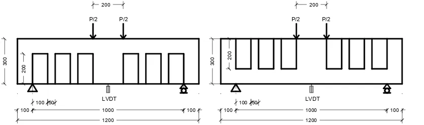
Shear retrofitting using CFRP as per ACI 440 does not distinguish the shape and the placement of the CFRP wrap, be it full block, or intermittently installed n shape or u shaped of CFRP wrap. One layer of CFRP sheet having thickness of 0.131 mm with the dimension of 100 mm x 200 mm and 150 mm spacing, its shear contribution is 18.88 kN. Thus, the predicted shear capacity of the RC beam reinforced using CFRP is 95.26 kN which is the total shear capacity of the control beam and the CFRP. The ultimate load prediction is therefore 190.53 kN. The CFRP is not fully wrapped vertically to take into account the presence of the floor slabs. The load setting is shown in Figure 1.
Figure 1: The load setting of RC beam reinforced by n shaped (left) and u shaped (right) of CFRP In this experiment, the distance from the point load to the support (a) is 400 mm and the effective height of beam (d) is 254.5 mm. It can be expected that with a/d ratio of 1.57 the RC beam will be collapsed in shear failure. The third test was performed until the beam was collapsed.
Results and Discussion
Table 1 shows the experimental results of the ultimate load (Pultimate) of the RC beams. Pultimate of RC
beams with n shaped of CFRP is shown to be higher than that of the RC beams reinforced with u
shaped CFRP.When the ultimate load is calculated based on ACI 440, the increase in ultimate load (Pcode) between the retrofitted beams, be it n or u shaped of CFRP reinforcement, and the control
beam is 37.77 kN. However, on the other hand the experiment shows that the increase of Pultimate of
RC beams reinforced with u shaped and n shaped of CFRP to Pcode of the control beam are 53.47 kN
and 102.07 kN respectively. This shows that the ACI 440 provides very conservative design in calculating the ultimate load of the RC beam retrofitted using CFRP in negative moment area.
Table 1:Experimental results
Beam Type P ultimate (kN) P code (kN) P ultimate increment (%) P code increment (%)
Control beam 160.38 152.76 0 0
Beam with U shape 206.23 190.53 35.00 24.72
Beam with N shape 254.83 190.53 66.82 24.72
In the study conducted by Namboorimadathil [1] on reverse T beams having both flexural and shear retrofit systems using FRP fully installed along its longitudinal direction, Pultimate of retrofitted
beam was found to be 39% greater than Pultimate of their control beam. It was said that when the load
approached its ultimate load, the shear FRP debonded near the load, however the failure of the beam was still due to flexure. This indicated that the shear capacity of the retrofitted T beam was still way beyond that.
Meanwhile in this study, as shown in Figure 1, the shear reinforcement using CFRP wraps is provided on its longitudinal direction intermittently leaving a 50 mm gap between each CFRP wrap. The test is carried out without any flexural retrofit system. Herein, the Pultimate of RC beams
retrofitted using n shaped and u shaped of CFRP increase of about 66.82 % and 35 % from the
Pultimate of the control beam respectively. Such a difference is expected as the n shaped CFRP wrap
system provides additional confinement to the compressive concrete, a thing that the u shaped system is lacking.
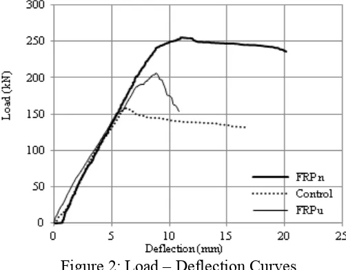
Figure 2: Load – Deflection Curves
Figure 2 shows load-deflection curves of the experiment carried out. It is clearly shown that n
shaped system is more ‘ductile’ than the control beam and the u shaped system. The u shaped system is found to be the most brittle among the three.
Figure 3: Shear failuresof RC beams strengthened by n (left) and u (right) shaped of CFRP The shear failure modes of both the retrofitted RC beams are shown clearly in Figure 3. The diagonal cracks appear, connecting the load point and the support, and then followed by the debonding of CFRP sheet.In the case of RC beam with n shaped of CFRP, flexural micro cracks are observed which makes the retrofitted beam more ductile than that of the u shaped CFRP.
Conclusion
Based on the aforementioned analysis and discussion, the conclusions are as follows:
• The difference of the shear capacity obtained between RC beams retrofitted using n and u shapes of CFRP sheets is mainly caused by the presence (n) and the absence (u) of concrete confinement by the C FRP sheet, respectively.
• The difference between the experimental shear capacity of RC beam retrofitting by n shaped of CFRP and the design shear capacity calculated using ACI 440 is very significant. Further study is required to take into account the concrete confinement effect of n shaped CFRP to optimize the shear capacity of the beam as it has not been covered in ACI 440.
• The beam retrofitted using n shaped of CFRP achieves higher ductility than the beams retrofit with u shaped of CFRP wrap.
• ACI 440 provides quite a conservative design of shear capacity of RC beam reinforced using CFRP.
Acknowledgements
This research was supported by PT. Sika Indonesia by providing the CFRP wraps (Sika Wrap-231C) and Epoxy Impregnation Resin (Sikadur-330).
References
[1] Namboorimadathil Sinaph M; Gustavo Tumialan and Nanni Antonio, Behavior of RC T-Beams Strengthened in The Negative Moment Region with CFRP Laminates, ICCI 2002, San Fransisco, CA,June 10-12 2002.
[2] Daniel Baggio, Khaled Soudki, Martin Noel, Strengthening of Shear Critical RC Beams with Various FRP System, Construction and Building Materials 66 (2014) 634-644 Elsevier. [3] ACI 440.2R-08, Guide for the Design and Construction of Externally Bonded FRP Systems for
Strengthening Concrete Structures, ACI Commite 440, 2008.
[4] Zararis Prodromos, Shear Compression Failure in Reinforced Concrete Deep Beams, ASCE, Vol 129 No.4, 2003.