EXTRACTING SEMANTIC BUILDING MODELS FROM AERIAL STEREO
IMAGES AND CONVERSION TO CITYGML
A.Sengul a
a
ITU, Civil Engineering Faculty, Dept. of Geomatic Engineering, 80626 Maslak Istanbul, Turkey [email protected]
Commission III, WG IV
KEY WORDS: 3D City model, CityGML, Data model
ABSTRACT:
The collection of geographic data is of primary importance for the creation and maintenance of a GIS. Traditionally the acquisition of 3D information has been the task of photogrammetry using aerial stereo images. Digital photogrammetric systems employ sophisticated software to extract digital terrain models or to plot 3D objects. The demand for 3D city models leads to new applications and new standards. City Geography Mark-up Language (CityGML), a concept for modelling and exchange of 3D city and landscape models, defines the classes and relations for the most relevant topographic objects in cities and regional models with respect to their geometrical, topological, semantically and topological properties. It now is increasingly accepted, since it fulfils the prerequisites required e.g. for risk analysis, urban planning, and simulations. There is a need to include existing 3D information
science, government, and private industry. Several
municipalities decide nowadays to build up 3D city models in order to clearly understand the cities’ real situations. With the increasing number of more complex applications and objectives more sophisticated models are required not only based on geometric information, but onsemantic information as well as on 3D topology, representing the meaning and functionality of urban objects. CityGML, an OGC standard for city and landscape modelling, is able to identify structures for the organization of urban information which can be used in a broad range of applications, e.g., for analysis in urban planning, disaster management, and environmental simulations.
Traditionally, acquisition of 3D objects is done by photogrammetric methods, using aerial stereo images. Leica Photogrammetrry Suite (LPS) by Erdas for example, offers sophisticated tools for stereo feature collection. But there is a gap between the photogrammetric measurement and the storage of processed objects in CityGML which is filled by a student’s master thesis completed at the Technische Universität Berlin.
2. 3D CITY MODELLING
2.1 3D City Models
3D City Models are digital representations of the Earth’s surface and related objects belonging to urban areas. In order to get information about a city it is necessary to collect data from different sources. There are several methods of collecting the
data such as LIDAR, laser scanning, surveying measurements, aerial and satellite images…etc.
2.2 Semantic 3D City Models
Semantic 3D city models comprise besides the spatial and graphical aspects particularly the ontological structure including thematic classes, attributes, and their interrelationships. It follows structures that are given or can be observed in the real world. For example, a building can be decomposed into different building parts, if they have different roof types and their own entrances like a house and the garage (Kolbe,2009).
3.DATA MODELLING
Data modelling defines the relationships between data elements and structures. Data modelling techniques are used to model data in a standard, consistent, predictable manner in order to manage it as a resource (Carlis, 2001).
3.1 Building model in photogrammetric tools
The photogrammetric tools are combined with ERDAS Imagine – LPS and ArcGIS Stereo Analyst in the thesis work. The building data model of ERDAS which could not reach anywhere and it decided to build using UML diagram. Modelling the UML diagram of the ERDAS Imagine LPS module and ArcGIS Stereo Analyst is another task to follow on the project, while working on the photogrammetric methods. The UML diagram will help the user to follow the thesis work. It is representing the details of the workflow (Fig3.1).
International Archives of the Photogrammetry, Remote Sensing and Spatial Information Sciences, Volume XXXIX-B3, 2012 XXII ISPRS Congress, 25 August – 01 September 2012, Melbourne, Australia
Figure 3.1: Overview UML diagram of Photogrammetric Tool’s Building Model
3.1 UML diagram of building model in CityGML
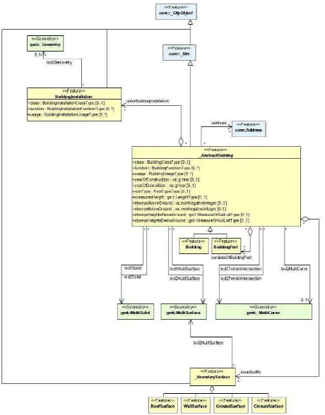
The City GML building model is minimized depending on the requirements of this paper work. The geometric representation and semantic structure of a Building model which defines as an _AbstractBuilding. The model is refined only from LOD1 to LOD2 due to the work purpose and requirement. For intuitive understanding of the UML model, classes will also be shown in different colours such as blue, green, yellow. The UML diagram of the building model is depicted in figure 3.2.
Figure 3.2: Overview UML diagram of City GML’s Building Model (Gröger, 2008)
Also, not all aggregation levels are allowed in each LOD. The geometric representation is refined in LOD2 by additional MultiSurface and MultiCurve geometries, used for modelling architectural details like a roof overhang, columns, or antennas. For the LOD 1-2 group the geometries gml_Solid, gml_MultiSurface and gml_MultiCurve are linked with the Abstract Building class (Gröger, 2008).
3.2 Comparision of the data models
When we compare the UML diagrams derived from the photogrammetric methods and ending with the CityGML Building model it is possible to define differences and similarities. The differences of the UML diagrams are defined such as complexity structure, XML based, Level of Detail (LODs) definition, geometry and semantic …etc. (Tab.1) In ERDAS LPS, the building model can be defined with the UML classes in the workflow. So that the user who has aerial stereo images can be build a building model in the program. Also, the CityGML Building Model is a standard for the representation and exchange of 3D city and landscape models, issued by the Open Geospatial Consortium.
Properties ERDAS LPS & ArcGIS Stereo
Analyst
CityGML
Complexity Structure No Yes
Semantic No Yes
XML based No Yes
Level of Details No Yes
Geometry Multipatch Multi Surface
Solid Type No Multi Solid
Predefined Structure No Yes
Table.1: It shows the differences between ERDAS LPS & ArcGIS Stereo Analyst and CityGML Data models
International Archives of the Photogrammetry, Remote Sensing and Spatial Information Sciences, Volume XXXIX-B3, 2012 XXII ISPRS Congress, 25 August – 01 September 2012, Melbourne, Australia
4.METHODOLOGY
To use technologies, which make the work possible are Digital Photogrammetric Workstations, Erdas Stereo Analyst, Stereo Analyst and Feature Assist for ArcGIS, FME and CityGML as an accepted data model for 3D GIS.
First of all the workflow is described using different colours and in different boxes referring the different programs which are used during the thesis work. Also on the workflow diagram the number refers to the steps which are in order on the thesis workflow. (Fig.4.1)
Figure 4.1: Workflow Diagram
During the workflow the following 19 steps which are listed below:
1. Adding Aerial Stereo images on ERDAS LPS and arranging to get 3D view
2. Defining the camera properties associated with the camera parameters
3. Orientation Parameters
A. Interior Orientation Parameters B. Exterior Orientation Parameters
4. Adding the Ground Control Points on ERDAS LPS 5. Building a Block Model in ERDAS LPS
6. Import the Block Model in the Arc GIS Stereo Analyst 7. Adding a Digital Terrain Model in ArcGIS
8. Editing the Terrain using the Terrain Editor 9. Adding Terrain on Feature Assist
10.Digitizing the roof structure from Aerial stereo images in 3D view using Feature Assist for ArcGIS
11.Chosing the roof template in ArcGIS Stereo Analyst to digitize it
12.Digitizing the building installations and merging with the building roof
13.Extruding the roof structure with Extrude Roof Base based on the terrain model.
14.Giving the attributes of the building,
15.Footprints of the buildings from Multipatch Shape file 16.Converting from “Multipatch” to “Polygonz” on FME
Workbench
17.Giving the attributes to the building's surface
18.Converting the building data from “Shape” to “CityGML” on FME Workbench
19.Displaying the CityGML data model in Land Explorer or Aristotales
The result of the thesis work is a valid CityGML building model. In this paper work the aerial images were only the data which have been used within ERDAS LPS Program and the 3D city model have been created as a result.
5. CONVERSION WITH FME
In this chapter, the main aim is filling the gap between photogrammetric tools and the CityGML data model has been solved by adding several transformers in the FME program. The conversion part is divided into two main part:
1. Conversion from ESRI Multipatch shape file format to ESRI PolygonZ shape file format with calculation of the building height. (Fig.5.1)
Figure 5.1: Conversion from ESRI Multipatch to ESRI PolygonZ shape file
International Archives of the Photogrammetry, Remote Sensing and Spatial Information Sciences, Volume XXXIX-B3, 2012 XXII ISPRS Congress, 25 August – 01 September 2012, Melbourne, Australia
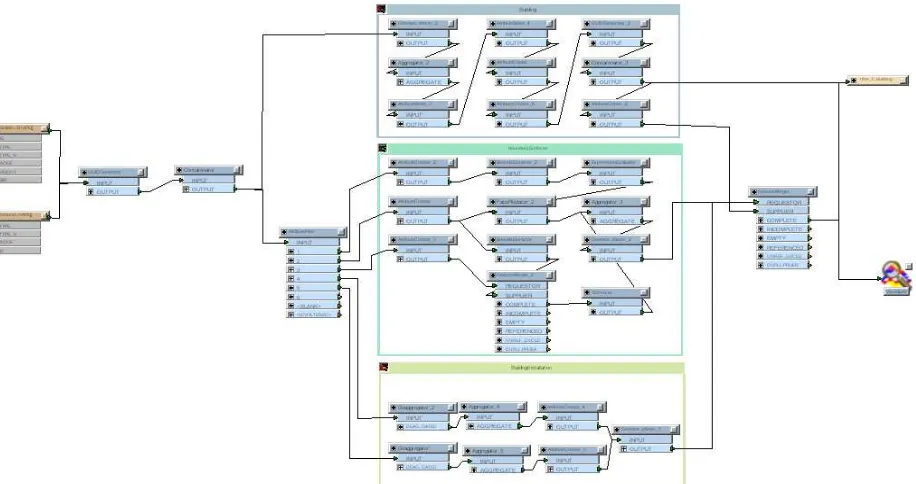
Figure 5.2: Conversion from ESRI PolygonZ shape file to CityGML data model
2. Conversion from ESRI PolygonZ Shape file to CityGML data model which is the main conversion task of the thesis work. Also the convertion is divided into three parts which are called bookmark in FME (Fig.5.2),
a. Building bookmark which includes general information about buildings and necessary attributes in order to have correct CityGML dataset.
b. Boundry Surface bookmark which includes the buildings surface informations, necessary attributes as well as extra attribute such as roof height.
c. Building Installations bookmark which includes the building installation necessary attributes in order to open properly in the CityGML data model.
Each Transformer needs necessary input data and should be in the right position in the FME workbench. Finally, the conversion has reached the destination data as CityGML, which is XML based format.
6. CONCLUSION
To sum up, the gap between photogrammetric methods and CityGML has been filled with a FME Workbench. Furthermore, the building model of photogrammetric methods has been created and also the building model of CityGML is minimized from the specification document depending on the requirements of the thesis work.. Also those building data models are compared with CityGML building model. The differences and similarities of those models have also defined and also they mapped eachother with using UML diagram.
7. REFERENCES
Kolbe, T. H., Gröger, G., Plümer, L. (2005), CityGML – Interoperable Access to 3D City Models. Proceedings of the first International Symposium on Geo-Information for Disaster Management, Springer Verlag.
Zlatanova, S., Paintsil, J. and Tempfli, K., 1998: 3D object reconstruction from aerial stereo images. In: WSCG '98, 6th international conference in Central Europe on computer graphics and visualization: February 9-13, 1998, Plzen-Bory, Czech Republic
Gröger, G., Kolbe, T.H., Czerwinski, A., Nagel, C., 2008. OpenGIS City Geography Markup Language (CityGML) Encoding Standard, Version 1.0.0, OGC Doc. No. 08-007r1, Open Geospatial Consortium
Kolbe, T.H, 2009, Representing and Exchanging 3D City Models with CityGML, 3D Geo-Information Sciences, ISBN: 978-3-540-87395-2, pp. 15-31
John Vincent Carlis, Joseph D. Maguire ,2001. Mastering Data Modeling: A User-driven Approach.
International Archives of the Photogrammetry, Remote Sensing and Spatial Information Sciences, Volume XXXIX-B3, 2012 XXII ISPRS Congress, 25 August – 01 September 2012, Melbourne, Australia