IMPROVING CAR NAVIGATION WITH A VISION-BASED SYSTEM
H. Kim, K. Choi, I. Lee*
Dept. of Geoinformatics, The University of Seoul, 163 Seoulsiripdaero, Dongdaemun-gu, Seoul 130-743, Korea - (zzimss, shale, iplee)@uos.ac.kr
Commission III, WG III/3
KEY WORDS: Position and Attitude, Car Navigation, Intelligent Vehicle, Single Photo Resection
ABSTRACT:
The real-time acquisition of the accurate positions is very important for the proper operations of driver assistance systems or autonomous vehicles. Since the current systems mostly depend on a GPS and map-matching technique, they show poor and unreliable performance in blockage and weak areas of GPS signals. In this study, we propose a vision oriented car navigation method based on sensor fusion with a GPS and in-vehicle sensors. We employed a single photo resection process to derive the position and attitude of the camera and thus those of the car. This image georeferencing results are combined with other sensory data under the sensor fusion framework for more accurate estimation of the positions using an extended Kalman filter. The proposed system estimated the positions with an accuracy of 15 m although GPS signals are not available at all during the entire test drive of 15 minutes. The proposed vision based system can be effectively utilized for the low-cost but high-accurate and reliable navigation systems required for intelligent or autonomous vehicles.
1. INDRODOUCTION
The Intelligent vehicles are improved automobile in terms of driver safety and comfort, and are based on mechanical, electronic, telecommunication and control engineering fields. As complexity and challenges in today’s traffic are growing, interest in the intelligent vehicle, that is accident-free and with autonomous driving function, is increasing. The autonomous driving vehicles travel to their destination without driver’s manual intervention while recognizing their surrounding environment and position. These autonomous driving vehicles reduce the chance for accidents and fuel consumption as well as improve driver safety and comfort (Bishop, 2000). On the roadmap to the autonomous driving vehicle, we are currently on the semi-autonomous driving stage where adaptive cruising or/and lane keeping are possible. To realize the next stage in the roadmap, the autonomous driving, three kinds of important issues have to be addressed. They are 1) high precision positioning and mapping, 2) omni-directional sensing, 3) driving situation grasp and actuators control. The first issue among the three matters is related to navigation which needs to know a car’s position on a map and guide the best route by comparing the position and a destination. The autonomous driving vehicle technologies so far depend on high price LiDAR (Light Detection And Range) and GPS (Global Positioning System) to estimate their position and recognize surrounding environments.
Google, the world’s biggest IT company, employs sensors of hundreds of millions of dollars such as radars, 3D LiDAR, GPS/INS/Encoder and others for self-driving cars. Global automobile manufacturers such as Mercedes-Benz, BMW, Audi are also developing self-driving cars relying on expensive high performance sensors (Franke et al., 2013). Those companies announced they are in nearly complete phase of hardware technologies like the sensors for the self-driving cars, and they will complete the self-driving car by 2017 through complementing software technologies like navigation. However, in order to commercialize the self-driving cars, there is a matter
* Corresponding author
of cost that prices of sensors applied to them are too expensive and go up by more than those of basic vehicles. It is expected to need long time until the prices of the sensors and peripheral equipment go down to the suitable level for the commercialization. To advance the commercialization date, we have to avoid using the high price sensors and suggest an alternative. As a part of the alternative, some researches have conducted to combine existing GPS used to current car navigation system with the other lower priced sensors such as cameras and an INS.
performance at high speed and fast turn scenarios. Jung et al. (2012) proposed a dead reckoning algorithm using low-cost GPS and in-vehicle sensory data that is velocity and heading angle. The algorithm is based on a Kalman filter and can exclude low accuracy GPS data by selecting a vehicle model between kinematic and dynamic models.
Many of modern cars have built-in front and around view monitoring cameras or additionally equipped black box cameras to protect drivers and vehicles. While the cameras are low-priced, the precision of relative positioning using the images is high as compared with other navigation sensors. Furthermore, we can easily obtain image sequences during driving, hybrid approaches using images for positioning also seem to be promising (Soloviev and Venable, 2010; Kim et al., 2011; Yoo et al., 2005, Kim et al., 2004; Goldshtein et al., 2007). Single camera or more cameras’ images are used with GPS data to enhance the positioning accuracy in many studies. Caraffi et al. (2012) presented a system for detection and tracking of vehicles from a single car-mounted camera. Though the system showed high potential for positioning using images from a single camera, had some constraint condition and was far from perfect in terms of automation. Mattern and Wanielik utilized landmarks images in combination with a low-cost GPS, a detailed digital map, and in-vehicle odometer to localize a vehicle at intersections where it is difficult to recognize which road or lane is actually taken, although the reception of GPS signal is good (Mattern and Wanielik, 2010). Nath et al. (2012) developed an algorithm to estimate 3D position of moving platform equipped with a camera employing an adaptive least squares estimation strategy. They showed the effectiveness of the proposed algorithm using only simulated data. Oskiper et al. (2012) presented a navigation system using a MEMS IMU, GPS and a monocular camera. They performed the fusion the IMU and camera in a tightly coupled manner by an error state extended Kalman filter. Soloviev and Venable (2010) investigated into the feasibility of the combination of GPS and a single video camera for navigation in GPS-challenged environments including tunnel or skyscraper area where GPS signal blockage occurs. They also demonstrated the performance of the method using only simulated data. Kim et al. (2011) employed omnidirectional cameras to overcome narrow field of view and in-vehicle sensors, an odometer. The system provided accurate results but the used sensors are still too expensive to commercialize.
Precise digital map, which includes in-depth information on each lane, road features, can be also used to improve positioning accuracy. If a precise map data are constructed well, it could be powerful tool for upgrade the estimation results. However, precise map generation and generated data management are a laborious task. And the parameter definition of the map data and generated data sorting are also hard to treat well. Therefore there are some studies about how to generate and use the map data effectively. Ziegler et al. (2014) developed an autonomous car using precise digital map and multiple cameras, in-vehicle sensors. The car is equipped with multiple computers in order to manage huge map data and compute in real-time. They acquired the image from the cameras, and convert them to map and feature data. Through this process, reference map and trajectory is generated. After the procedure, the car drive same route again and acquire various sensory data. Comparing acquired data to reference data, they can get current position and decide where to drive. The test driving was successful. However, this autonomous car is a map dependent system and it only can drive where the data base exist. And the data for autonomous driving are excessively large. Thus it still need time to apply for real life. In this paper, we propose a precise car positioning method to enhance existing GPS performance or get over GPS signal problem based sensor fusion. For this, we use a front view camera,
in-vehicle sensors and the existing GPS, and adopt an extended Kalman filter to integrate the multi-sensory data. To check the feasibility of our proposed method, we implement the algorithm and construct data acquisition system. We conduct and evaluate the experiment using real data from the system. The remaining part of this paper is organized as follows. The framework of the proposed system and experiment are discussed in section 2 and section 3 in order, and conclusions are followed in section 4.
2. VISION BASED NAVIGATION FRAMEWORK AND METHOD
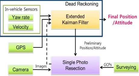
To estimate the position and attitude of a car more accurately, we design a sensor fusion framework combining a camera, a GPS and in-vehicle sensors. As the acquisition time and period and the accuracy of these sensory data are different, we utilize an Extended Kalman Filter (EKF) for sensor fusion. This framework enables to produce the accurate position of a moving car even in GPS interference places. The overall framework is shown in Figure 1. It includes three main processes: (1) dead reckoning using in-vehicle sensors, (2) image georeferencing based on Single Photo Resection (SPR), (3) sensor fusion using an Extended Kalman Filter. The dead reckoning process determines the preliminary position and attitude using the in-vehicle sensory data such as yaw-rates and velocities. The image georeferencing process estimates the position and attitude of a camera and thus those of the car at the time of the image exposure using ground control points. Finally, the EKF process combines individual sensory data and produce the final enhanced position and attitude. The remaining parts of this section explain more details about each process.
Figure 1. The proposed position and attitude estimation framework
2.1 Dead Reckoning using In-vehicle Sensors
���((��))�=���(0)
(0)�+ ∫ �(�)���� � (�) ��� �(�)� ��
�
0 , (1)
�(�) =�(0) + � �(�)��
�
0 , (2)
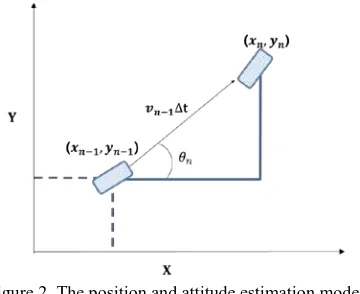
where (x,y) and θ indicate the position and direction of the car; v and w are the velocities and yaw rates from the in-vehicle sensors. Actually, in this formula, we don’t consider the variation of elevation in the position and thus all the variables are defined in a 2D coordinate. It is because the in-vehicle sensory data cannot provide accurate information on the elevation change. With such data, we estimate the horizontal position only. Eqs. (1) and (2) can be discretized as
������=���0
0�+ ∑ ������ � �
��� ��� ∆� �−1
�=0 , (3)
��=�0+ ∑�−1�=0��∆�, (4)
where ∆t is the computation update interval; n and k denote sampling at time t=n•∆t and t=k•∆t. Eqs. (3) and (4) can be rewritten as
������=����−1
�−1�+ ��−1���� � �−1
��� ��−1� ∆�, (5)
��=��−1+ ��−1∆�. (6)
The current position and attitude at time n can be updated from the previous position and attitude at time (n-1) with the velocity and yaw rate of the time interval between (n-1) and n. With a short time interval, we assume that the velocity and yaw rate are maintained constantly as the values transmitted from the CAN bus at time (n-1). This update model is shown in Figure 2. Using these equations, the system can determine the relative position and attitude from the initial values. Furthermore, if the system obtains the initial status in an absolute coordinate system from a GPS/INS sensor, it can determine the position and attitude in the absolute coordinate system all the time.
Figure 2. The position and attitude estimation model
2.2 Image Georeferencing Based on Single Photo Resection
To increase the accuracy of the preliminary position and attitude, we combine the image georeferencing results based on Single Photo Resection (SPR). The SPR process determines the extrinsic camera parameters such as the position and attitude at the acquisition time of an image using the ground control points (GCP). Since the camera is rigidly mounted on a car, the position and attitude of the camera can be transformed into those of the car, which be effectively used to enhance the preliminary position
and attitude. For the accurate transformation, we require the mounting parameters to describe how the camera is mounted on the car. These parameters are usually the position and attitude of the camera in the car body coordinate system, which should be determined by a prior system calibration process.
The SPR process is based on the collinearity equations that represent the mathematical relationship between an object point and its projected image point. These equations are abstractly expressed as Eq. (7), where (x,y) describes an image point; and (��,��,��) does an object point. (��,��,��) and (ω,ϕ,κ) indicate
the position and attitude of the camera, respectively.
(�,�) =�(��,��,��,�,�,�,��,��,��).
(7)
A pair of an object point and its corresponding image point provides two equations similar to Eq. (7). If we know the coordinates of the object point and find its corresponding image point using an image matching process, only six extrinsic camera parameters remain unknown. In theory, if we have more than three pairs providing six equations, we can solve this simultaneous equations to determine the camera parameters. Such object points with known coordinates are called ground control points.
As shown in Figure 3, the single photo resection process requires four kinds of inputs such as ground control points, image points, intrinsic camera parameters and preliminary (or initial) extrinsic camera parameters. The ground control points are determined through GPS and total station survey. The image points are the points appearing in an image, which are corresponding to the ground control points. The intrinsic parameters means the parameters related to the optics of the camera, such as the focal length, the principal point, and lens distortion parameters. Although the extrinsic parameter are the output of the SPR process, we need initial approximations to such unknowns to solve the non-linear simultaneous equations. The initial values can be derived from GPS and in-vehicle sensory data. With these inputs, for each image, the SPR process produces the extrinsic parameters improved from the initial values. The accuracy of such extrinsic parameters mainly depends on the number, distribution, and accuracy of the ground control points.
Figure 3. The procedures of the SPR process
2.3 Sensor Fusion Using an Extended Kalman Filter
In this process, the GPS data, in-vehicle sensory data and the image georeferencing results are combined together. For the accurate estimation of the position and attitude, we designed and used the EKF method. Whenever a kind of these data are acquired, position and attitude are estimated through an EKF process. The EKF that used in this paper is designed with six state parameters described in Table 4.
Parameter Description
�, y, z Position
� Direction
� Velocity
� Yaw rate
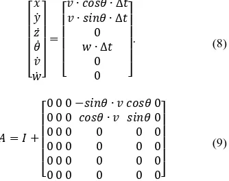
According to Eqs. (5) and (6), the state equations of the EKF are mainly derived from the dead reckoning process, being expressed as Eq. (8). The state variables (z,v,w) not being directly affected from the in-vehicle sensory data are assumed to be constant. These non-linear state equations are further linearized as Eq. (9).
⎣
Based on the prediction equations, the system keeps producing its predictions until new measurements occur. With the new measurement, the EKF calculates the Kalman gain value, state and covariance values. According to the kinds of the measurements, we derive different measurement models being represented Eqs. (10-12).
where Z vector represents the measurement vector and H matrix does the relationship between the state and measurements. Whenever the sensor data are measured, the corresponding equations are used. Eq. (10) is used when the image georeferencing results are obtained. Similarly, Eqs. (11) or (12) is used when the GPS or in-vehicle sensor measurements are updated.
3. EXPERIMENT
To demonstrate the feasibility of the proposed method, we constructed a data acquisition system that can acquire the GPS, image and in-vehicle sensory data. Furthermore, we mounted the reference data acquisition equipment for accuracy evaluation. Before the position and attitude estimation, we verified the accuracy of the in-vehicle sensory data. We then estimated car position and attitude using the proposed algorithm. To evaluate the accuracy of the in-vehicle sensory data and the estimation results, we compare them with the reference data.
3.1 Experimental Description
We designed the data acquisition system for various sensor data acquisition and storing. This system acquires GPS data, images, in-vehicle sensory data and reference data. The in-vehicle sensory data can be collected through the CAN bus on a vehicle such as velocity and yaw-rate. For the collection, we built a data
acquisition board, which collects the data through the CAN bus and transmit them to a laptop through a RS232 port. The acquisition system also has a front view camera, GPS and reference equipment (POSLV 420, Applanix). The specifications of the camera are summarized in Table 5. The specifications of the reference equipment are described in Table 7 (Applanix, 2012). With this reference equipment, we can determine the 3D position of a moving car in an accuracy of less than 5 cm after post-processing. The overall data acquisition process is described in Figure 6 and the constructed system mounted on the car is shown in Figure 8. We mounted a GPS, a front view camera and a reference device on the roof of the car. Using a laptop inside of the car, we can collect and monitor the receiving sensory data in real time while the car is moving.
Parameter Value Unit
focal length 6 mm
resolution 1024 x 768 pixels
pixel size 4.65 μm
Table 5. Specification of the camera
Figure 6. The configuration of the data acquisition process
Figure 8. The data acquisition system mounted on the car
This data acquisition system uses various sensors. The update frequency of each sensor is different. Besides, the in-vehicle sensors and camera do not inherently provide the accurate time tag of each data. Hence, when the data acquisition board collects the sensory data, it record the data with an accurate acquisition time based on its built-in clock. This clock is set to the GPS time, when the board is initialized with a GPS. In this way, all the sensory data are then collected and recorded with GPS time tags in real time.
The experiment has been conducted on an urban road in Seoul, Korea. The test vehicle was a Hyundai Santa Fe DM and the driving time was approximately 15 minutes. The trajectory is shown in Figure 9 as a red line. We planned the trajectory to include straight and curved sections. It is a loop trajectory, where we finish the drive at the starting point to check the estimated finishing point is the same as the starting point.
Figure 9. The test site and trajectory (a red line)
3.2 Accuracy Verification of In-vehicle Sensors
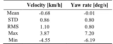
The proposed system use in-vehicle sensors for estimation but the car manufacturer does not open the specification of the sensors. We conducted the accuracy verification of the in-vehicle sensors before the estimation process. For the verification, we compare the acquired in-vehicle data with the reference data. The comparison results are shown in Figure 10 and 11. As shown in Table 12, the RMS of the discrepancy with respect to velocity and yaw rate are 1.1 km/h and 0.8 deg/s, respectively.
Figure 10. The velocity difference between in-vehicle sensor and reference data
Figure 11. The yaw rate difference between in-vehicle sensor and reference data
Velocity [km/h] Yaw rate [deg/s]
Mean -0.68 -0.01
STD 0.86 0.80
RMS 1.10 0.80
Max 3.87 7.20
Min -4.55 -6.19
Table 12. The discrepancy between built-in sensor data and reference data
3.3 Estimation Results
The estimated results are shown in Figure 13, presenting three trajectories. The blue line indicates the trajectory from the reference data, being regarded as the true one. The green line is the one determined from in-vehicle sensory data only. Lastly, the red line is the one determined from the sensor fusion results with in-vehicle sensory data and the image georeferencing results. The cyan circle means the positions where the SPR results are available. According to the results, the sensor fusion results are more close to the reference data.
Figure 13. The comparison of the estimated trajectory
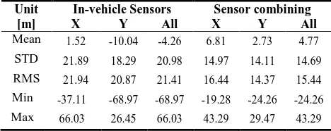
Figure 14 shows the distance differences comparing to the reference data. The red line means the comparison results of the in-vehicle sensor only method and the blue dashed line does the comparison result from the sensor fusion method. Table 15 indicates the error statistics comparing with the reference data. The RMSE of the in-vehicle sensor only method and the proposed sensor fusion method are 21.4 m and 15.4 m respectively. This figure and table show the proposed estimation method is effective to reduce errors although we use only 9 SPR results.
Figure 14. The estimated position difference
Unit [m]
In-vehicle Sensors Sensor combining
X Y All X Y All
Table 15. Error statistics of the estimation results
4. CONCLUSIONS
We presented an improved car navigation system based on visual localization. A front view camera, GPS and in-vehicle sensors are employed for this system. An EKF based sensor fusion method is proposed to combine several sensory data and estimate the car’s position and attitude. The proposed method combines in-vehicle sensor data, GPS data and image georeferencing results. It estimates the position and attitude every computation period or whenever new sensory data are acquired. Through this process, it can estimate the position and attitude more accurately. Moreover, it provide robust estimation results although the GPS signal blockage of a long period occurs. For verification, we have implemented the proposed estimation method and constructed the corresponding data acquisition system. This system acquires and archives the in-vehicle sensory data, image data and reference data during the test drive at the same time. The experimental results show that the proposed sensor fusion method can estimate the trajectory more accurately than the in-vehicle sensor only method. The RMSEs in the estimated trajectory using the sensor fusion method are 15.4 m although only 9 sets of image georeferencing results are combined during the 15 minute drive with no GPS signals at all.
Consequently, the proposed image based sensor fusion method can compensate the limitation of GPS dependent systems. In the near future, we will change the front view camera to stereo cameras to enhance the image based estimation algorithm. Furthermore, not only a single image based algorithm such as the SPR algorithm but also many image based estimation algorithm such as bundle adjustment will be investigated. Finally, it will be applied to a real time car navigation system.
ACKNOWLEDGEMENTS
This research was supported by the Industrial Strategic Technology Development Program (10042808, Development of Driver Assistance Systems Using Camera, Radar and Road Characteristics) funded by the Ministry of Trade, Industry and Energy (MOTIE, Korea).
REFERENCES
Applanix. Available online: http://www.applanix.com/media/downloads/products/specs/posl
v_specifications.pdf (12 Sep. 2014).
Bishop, R., Intelligent vehicle applications worldwide. Intelligent Systems and their Applications, IEEE 2000, 15, 78-81.
Caraffi, C.; Vojir, T.; Trefny, J.; Sochman, J.; Matas, J., A system for real-time detection and tracking of vehicles from a single car-mounted camera, Intelligent Transportation Systems (ITSC), 2012 15th International IEEE Conference on, 16-19 Sept. 2012; pp. 975-982.
Franke, U.; Pfeiffer, D.; Rabe, C.; Knoeppel, C.; Enzweiler, M.; Stein, F.; Herrtwich, R.G., Making Bertha See, Computer Vision Workshops (ICCVW), 2013 IEEE International Conference on, 2013; pp. 214-221.
Goldshtein, M.; Oshman, Y.; Efrati, T., Seeker gyro calibration via model-based fusion of visual and inertial data, Information Fusion, 2007 10th International Conference on, 2007; pp. 1-8.
Jung, H.; Lee, D.; Kim, S.; Kim, C.; Huh, K., Development of vehicle position estimator using dead reckoning algorithm, Annual Conference and Exhibition, 2012; pp. 1255-1257.
Jo, K.; Chu, K.; Lee, K.; Sunwoo, M., Integration of multiple vehicle models with an IMM filter for vehicle localization, Intelligent Vehicles Symposium (IV), 2010 IEEE, 21-24 June 2010, pp. 746-751.
Kim, J.; Ridley, M.; Sukkarieh, S.; Nettleton, E., Real-time Experiment of Feature Tracking/Mapping using a low-cost Vision and GPS/INS System on an UAV platform. Journal of Global Positioning Systems 2004, 3, 162-172.
Kim, S.; Bazin, J.; Lee, H.; Choi, K; Park, S., Ground vehicle navigation in harsh urban conditions by integrating inertial navigation system, global positioning system, odometer and vision data. Iet Radar Sonar Nav 2011, 5, 814-823.
Madison, R.; Andrews, G.; Paul, D.; Rasmussen, S.; Bottkol, M., Vision-Aided Navigation for Small UAVs in GPS-Challenged Environments. In AIAA Infotech@Aerospace 2007 Conference and Exhibit; American Institute of Aeronautics and Astronautics: 2007.
Martin, S.; Rose, C.; Britt, J.; Bevly, D.; Popovic, Z., Performance analysis of a scalable navigation solution using vehicle safety sensors, Intelligent Vehicles Symposium (IV), 2012 IEEE, 2012; pp. 926-931.
Mattern, N.; Wanielik, G., Camera-based vehicle localization at intersections using detailed digital maps, Position Location and Navigation Symposium (PLANS), 2010 IEEE/ION, 4-6 May 2010; pp. 1100-1107.
Nath, N.; Dawson, D.M.; Tatlicioglu, E., Euclidean Position Estimation of Static Features Using a Moving Uncalibrated Camera. Ieee T Contr Syst T 2012, 20, 480-485.
Oskiper, T.; Samarasekera, S.; Kumar, R., Multi-sensor navigation algorithm using monocular camera, IMU and GPS for large scale augmented reality, Mixed and Augmented Reality (ISMAR), 2012 IEEE International Symposium on, 5-8 Nov. 2012; pp. 71-80.
Pavelková, L., Vehicle position estimation using GPS/CAN data based on nonlinear programming, Proceedings of the 13th IASTED International Conference on Intelligent Systems and Control, 2011.
Rezaei, S.; Sengupta, R., Kalman filter-based integration of DGPS and vehicle sensors for localization. IEEE Control Systems Techonology, 2007, 15, 1080-1088.
Soloviev, A.; Venable, D., Integration of GPS and vision measurements for navigation in GPS challenged environments, Position Location and Navigation Symposium (PLANS), 2010 IEEE/ION, 4-6 May 2010, pp. 826-833.
Yoo, J.; Choi, J.; Sung, K.B.; Kim, J., Vehicular image based geographic information system for telematics environments-integrating map world into real world, Geoscience and Remote Sensing Symposium, 2005. IGARSS'05. Proceedings. 2005 IEEE International; pp. 1206-1209.