INCREMENTAL REAL-TIME BUNDLE ADJUSTMENT FOR MULTI-CAMERA
SYSTEMS WITH POINTS AT INFINITY
Johannes Schneider, Thomas L¨abe and Wolfgang F¨orstner
University of Bonn, Institute of Geodesy and Geoinformation Department of Photogrammetry, Nussallee 15, 53115 Bonn, Germany
[email protected],{laebe, wf}@ipb.uni-bonn.de, http://www.ipb.uni-bonn.de
KEY WORDS:Incremental Real-time Bundle Adjustment, Visual Odometry, Multisensor Camera
ABSTRACT:
This paper presents a concept and first experiments on a keyframe-based incremental bundle adjustment for real-time structure and motion estimation in an unknown scene. In order to avoid periodic batch steps, we use the software iSAM2 for sparse nonlinear incremental optimization, which is highly efficient through incremental variable reordering and fluid relinearization. We adapted the software to allow for (1) multi-view cameras by taking the rigid transformation between the cameras into account, (2) omni-directional cameras as it can handle arbitrary bundles of rays and (3) scene points at infinity, which improve the estimation of the camera orientation as points at the horizon can be observed over long periods of time. The real-time bundle adjustment refers to sets of keyframes, consisting of frames, one per camera, taken in a synchronized way, that are initiated if a minimal geometric distance to the last keyframe set is exceeded. It uses interest points in the keyframes as observations, which are tracked in the synchronized video streams of the individual cameras and matched across the cameras, if possible. First experiments show the potential of the incremental bundle adjustment w.r.t. time requirements. Our experiments are based on a multi-camera system with four fisheye cameras, which are mounted on a UAV as two stereo pairs, one looking ahead and one looking backwards, providing a large field of view.
1 INTRODUCTION
The presented work is part of the visual odometry package within the DFG-project Mapping on Demand (MoD) at the University of Bonn and the Technical University of Munich, in which we use a lightweight autonomously navigating unmanned aerial vehicle (UAV). The goal of the project is the development and testing of procedures and algorithms for the fast three-dimensional seman-tic mapping of inaccessible objects.
The on-board sensing of lightweight UAVs has to be designed with regards to their limitations in size and weight, and limited on-board processing power requires highly efficient algorithms. In this project we use a quadrocopter, equipped with a GPS unit, an IMU, ultra sonic sensors, a 3D laser scanner, a high resolu-tion camera and four fisheye cameras, which are mounted as two stereo pairs, one looking ahead and one looking backwards, pro-viding a large field of view, see Fig. 1. The two stereo cameras are used (a) besides the ultra sonic sensors and the laser scan-ner for obstacle perception in the environment for autonomous navigation and (b) besides the GPS-unit and IMU for ego-motion estimation. The goal is to use the on-board processed ego-motion as an initial estimate for the orientation of the images of the high resolution camera, taking images with about 1 Hz, for near real-time semantic surface reconstruction on a ground station.
The four cameras with Lensagon BF2M15520 fisheye lenses with a field angle up to 185◦ capture four image sequences with a
frame rate of 14 Hz in a synchronized way. The basis between the cameras amounts to 20 cm providing highly overlapping views at each time of exposure, see Fig. 2. The monochromatic im-ages have a resolution of 752×480 pixels. In this paper we treat the issue of visual odometry for real-time ego-motion estimation using the synchronized images of the multi-camera system in a keyframe-based fast incremental bundle adjustment.
Bundle adjustmentis the work horse for orienting cameras and determining 3D points. It has a number of favorable properties,
Figure 1: Illustration of the UAV, one stereo pair is looking for-ward and one backfor-wards providing a wide field of view.
e.g. it is statistically optimal in case all statistical tools are ex-ploited and it is highly efficient in case sparse matrix operations are used and variable reordering is done to prevent unnecessary fill-in. Our previous work yielded a rigorousbatch bundle ad-justmentfor omnidirectional and multi-view cameras for an ef-ficient maximum-likelihood estimation with scene points at in-finity, called BACS (bundle adjustment for camera systems), see (Schneider et al., 2012). Multi-camera systemscan be used like
omnidirectional camerasto augment the effective aperture angle.
Far or even ideal points, i.e. points at infinity, e.g. points at the horizon, have been proven to be effective in stabilizing the orien-tation of cameras, especially their roorien-tations.
In this paper we focus on our concept for the visual odometry with a multi-view camera system consisting of omnidirectional cameras using the iSAM2 algorithm for a keyframe-based incre-mental real-time bundle adjustment.
The paper is organized as follows. In the next section we present our prototype realizing the image processing for data acquisition and reliable data association and the robust orientation of a set of frames taken in a synchronized way. Further, we show how the sparse non-linear incremental optimization algorithm iSAM2 can eliminate the need for periodic batch bundle adjustment steps for mapping and motion estimation on sets of keyframes. We follow up in section 3 with first experiments regarding the achieved tim-ings and observed properties of the algorithm used. Finally we conclude and give an outlook on our future work in section 4.
Related Work. Real-time bundle adjustment has been tack-led intensively in the photogrammetric community, see e.g. the review by Gr¨un (1987). It has recently attracted researchers in videometry for real-time visual odometry. Basic techniques for achieving real-time capabilities are Kalman-filter (Davison, 2003; Choi and Lee, 2012), sliding bundle adjustment (Engels et al., 2006) and incremental bundle adjustment (Mouragnon et al., 2009), the last two techniques aiming at higher stability in deter-mining the pose parameters. It is useful to exploit the sparsity during a sliding window bundle adjustment, cf. (S¨underhauf et al., 2005; Klein and Murray, 2007). Recently, filtering techniques based on bundle adjustment, have intensively been investigated. They use current image information to improve the past pose and map information. Strasdat et al. (2012) show that filtering all frames is inferior to using keyframes and that a high number of features is superior to a high number of frames. Incrementally up-dating the normal equations can be replaced by upup-dating the QR-factorization, described in detail in (Golub and Van Loan, 1996) and e.g. proposed for aerial on-line triangulation (Gr¨un, 1984). It has been realized for generic incremental maximum a poste-riori estimation by Kaess et al. (2008) in a first version without considering reordering or relinearization. A fluid relinearization and reordering has recently been published by Kaess et al. (2012) using a bayes-tree, published in (Kaess et al., 2010).
Multi-camera systems are regularly used for odometry, especially stereo camera systems, e.g. (Mostafa and Schwarz, 2001; Strasdat et al., 2012) and more than two cameras e.g. in (Maas, 1999) or (Kaess and Dellaert, 2006). Fisheye-Cameras, see e.g. (Abraham and F¨orstner, 2005), catadioptric cameras, see e.g. (Aliaga, 2001) or omnidirectional cameras, see (Tardif et al., 2008) ensure stable geometric positioning and full scene coverage due to their large field of view.
2 OVERALL CONCEPT
2.1 Overview
Visual odometry consists in determing the pose of the cameras in real-time. Our system uses feature points. The process consists of several steps:
1. The data acquisition and association detects feature points, performs the matching and provides camera rays associated with the previous and the other cameras.
2. The orientation of individual frames aims at providing ap-proximate values for the subsequent bundle adjustment and allows to select keyframes.
3. The incremental bundle adjustment uses the new informa-tion at a keyframe and merges it optimally with the previous information.
Figure 2: Example frame set taken with the four fisheye cameras in a synchronized way, that contains 50 feature points in each frame, which are tracked using the OpenCV implementation of the KLT tracker.
As the last step uses all available data and therefore is the most costly one, it needs to be an efficient one, to ensure real-time ca-pability, and requires the previous steps to guarantee outlier free information. Therefore we chose the software package iSAM2 for “incremental smoothing and mapping” for the third step and aim at efficient methods for reliable data association. The steps are now described in more detail.
2.2 Data Acquisition and Association
Our system for visual odometry is based on interest points, which are tracked in the individual cameras using the OpenCV imple-mentation of the KLT tracker. Interest points are corners in the gradient image with a large smallest eigenvalue of the structure tensor, cf. (Shi and Tomasi, 1994), and detected by using the functioncvGoodFeaturesToTrackand tracked using the func-tion cvCalcOpticalFlowPyrLK, which implements the itera-tive Lucas-Kanade method with pyramids according to Bouguet (2000). Fig. 2 shows an example of extracted feature points in the images of the four fisheye cameras.
Tracked feature points are converted into ray directions pointing to the observed scene points in the individual camera systems. For this we model the fisheye objective with the equidistant-model described in (Abraham and F¨orstner, 2005) allowing for ray directions with an intersection angle equal or larger than 90◦
to the viewing direction. The interior orientation of each cam-era is determined in advance by camcam-era calibration according to Abraham and Hau (1997) using Chebyshev polynomials. Using the equidistant-projection and applying all corrections to the fea-ture points, we obtain image pointse
x
lying closer to the prin-cipal pointH
than the gnomonic projectionsgx
of the observed scene points, see Fig. 3. The spherically normalized ray directionkx′scan be derived frome
x
by using the normalized radialdis-tancer′ = |ex|growing with the angleφbetween the viewing
direction and the camera ray.
The uncertainty of the image coordinates can be transformed to the uncertainty of the directionkx′s of the camera ray via
vari-ance propagation yieldingΣkx′s kx′s. In all cases the covariance
matrix of the camera rays is singular, as the normalized 3-vector only depends on two observed image coordinates.
To match feature points in the overlapping images of a stereo camera pair, we determine the correlation coefficients between the local 7×7 image patches at the feature points in the left and right images. Using the known rotationR21and translation
x
k’
x e gx r
- ’kxs
s H
O
O g φ
Figure 3: Relation between sensor point, viewing direction and viewing ray.
Figure 4: Example images taken in a synchronized way in the left and right camera of a stereo pair. The extracted feature point in the left image on the rightmost car has the illustrated epipolar line in the right image. The matching point in the right image lies on the indicated yellow line and the corresponding local image patches show a high correlation.
pair, which is determined in advance according to Schneider and F¨orstner (2013), we can reduce the amount of possible can-didates to feature points lying with regard to their uncertainty close to the corresponding epipolar lines, see Fig. 4, by check-ing the significance of the contradiction to the coplanarity of [kx′s
1,R
2
1t
2
1,kx
′s
2]. We assume feature points with the highest
correlation coefficient ρ1 to match, if ρ1 is above an absolute
threshold, e.g. 0.8, and – if there is more than one candidate close to the epipolar line – the closest-to-second-closest-ratio
r =ρ2/ρ1with the second highest correlation coefficientρ2 is
lower than an absolute threshold, e.g. 0.7. Finally we check if this criterion holds also for all feature points in the left image if there are more than one feature points on the corresponding epipolar lines. This procedure leads in some rare cases to wrong matches, which can be detected with a third observing ray from another pose. Matched feature pairs in the stereo cameras are used be-neath visual odometry for fast obstacle detection by directly in-tersecting the corresponding camera rays using the known mutual orientations between the cameras within a stereo pair.
2.3 Orientation of a Set of Frames
A map in our context is a set of scene points
X
= {Xi, i =1, ..., I}. It is initialized by forward intersecting the matched ray directions in the stereo pairs in the initiating frame set.
The initiating frame set is chosen as the first keyframe set with a fixed pose
M
k, defining the coordinate system of the map up toscale. The indexkdenotes a motion of a set of keyframes
K
kofall keyframe sets
K
= {Kk, k = 1, ..., K} ⊂T
={Tt, t =1, ..., T}, taken out of the set
T
of all frame setsT
t,tbeing theindex referring to the time of exposure of a set of frames taken in a synchronized way.
After initialization of the map, robust estimates for the motion
M
tof the camera system in the map are computed at each timeof exposure t via simultaneous resection of all cameras. We
Figure 5: A two-camera system with fisheye camerasc= 1,2 with projection centers
Z
tc, rigid motionM
c and time-varyingmotion
M
t, having a field of view larger than180◦shown at twoexposure timest = 1,2observing two points
X
i, i = 1,2,X
1being close by and
X
2at infinity.use a generalized camera model with multiple projection centres
c= 1, ...,4and known system calibration, described by the mo-tion
M
cof each single camera from the camera system. Themea-surement equation, which considers mutually fixed single view cameras, allows the single cameras to be omnidirectional and al-lows for far or ideal scene points, reads as
vitc=JT(x′itc)N [I3|03]M− 1 c M−
1
t Xi (1)
with the homogeneous scene pointXi, motion matricesMtand
Mc, and the observed ray direction kx ′s
itc and residual vitc of
scene pointiin camera systemkat timet, see Fig. 5, whereby J(x) =null(xT)andN(x) =x/|x|.
We determine the solution for the six pose parameters of Mt
by a robust iterative maximum likelihood-type estimation down weighting observations with large residuals by minimizing the ro-bust Huber cost function, see (Huber, 1981). The rigid motions
M
care determined in advance using a rigorous bundle adjustmentestimating the system calibration as described in (Schneider and F¨orstner, 2013). Using the pose
M
t−1as the initial approximatevalue, the estimation for
M
tconverges in most cases after 2-3 fastiterations. This allows the orientation of set of frames taken with a high frame rate. A track of observations getting a low weight is put on the blacklist. Tracks on the blacklist are not considered in the following frames anymore.
2.4 Keyframe-Based Incremental Bundle Adjustment
Bundle adjustment refers to the sets of keyframes, which reduce the processing to some geometrically useful, tracked observa-tions. A new keyframe set with motion
M
kis initiated in case aminimal geometric distance to the last keyframe set with motion
M
k−1 is exceeded. In case a new keyframe set is initiated, theobservationsx′
ikcare used to update and refine the scene points
in
X
and poses inK
in the incremental bundle adjustment. We classify the tracked observations into two sets,x
′1 and
x
2′, wherex
′1 are the observations of scene points that are already in the
map and
x
′2denotes those observing new scene points. The map
is continually expanded as new keyframe sets are added. Initial values for new tracked scene points are obtained by forward inter-section with observations
x
′2, where we claim that each track
con-sists of at least three keyframe sets. Care has to be taken with the sign: We assume the negativeZ-coordinate of each camera sys-tem to be the viewing direction. The homogeneous representation of the scene points then need to have non-negative homogeneous coordinatesXi,4. In case of ideal points, we therefore need to
which are points at infinity in opposite directions. Intersected scene points that show large residuals in the observations are put on the blacklist and deleted in the data association. Observations
x
′2are assumed to be revised from corrupted tracks via the former
robust resection.
The map
X
and the set of poses inK
is simultaneously refined using bundle adjustment. For our real-time application the pro-cessing of a new keyframe setK
kneeds to be finished by the timethe next keyframe set is added. For the first ten keyframe sets we use batch bundle adjustments as the map contains only a small number of scene points yet. After that the new information are incrementally merged with the previous information, yielding a fast optimal solution for the bundle adjustment using iSAM2, see (Kaess et al., 2012).
Incremental Bundle Adjustment. For bundle adjustment we use the measurement equation
that is not linear in the scene points and pose parameters ofXi
andMk. Linearization of the non-linear model at the actual
lin-earization points, which is shown in detail in (Schneider et al., 2012), leads to the least squares optimization problem
d
∆x=argmin
∆x
kA∆x−bk2
Σ (3)
with the JacobianAthat contains for each observationx′ ikcthe
block entriesAikc, right hand side (RHS) vectorb, unknown up-dates∆xfor the scene point and pose parameters and for proper weighting the covariance matrixΣthat contains the covariance matrices of allx′
ikcthat we assume to be uncorrelated with each
other. Using the decorrelated JacobianA′ =
Σ−1/2A
, which re-tains the sparsity pattern ofA, yields in eq. (3) a metric withΣas identity matrix.
QR factorization ofA′ yieldsA′ = Q[RT0]TwhereR is up-per triangular andQ is orthogonal, see (Golub and Van Loan, 1996). Applying this factorization to the least squares prob-lem in eq. (3) with[dT,eT] = QTb yieldskA′∆x−bk2
= kR∆x−dk2
+kek2
, which becomes minimal ifR∆x = d, leading to the unique solution
R∆xd=d. (4)
AsRis upper triangular, we can solve for∆xdwith simple back-substitution. The expensive part is done by QR decomposition. The matrix R is calledsquare root information matrix, as the information matrix, i.e. the normal equation matrix, is given by N=RTR.
When a keyframe set is initiated with new measurements, gen-erating the JacobianW and RHSg, the previously calculated components ofRcan be reused yielding the new system
R 0
with updates∆x1 and∆x2 for the old and new parameters,
re-spectively. Instead of applying an expensive full QR factoriza-tion, the entries below the diagonal can be efficiently eliminated by using Givens rotations, see (Golub and Van Loan, 1996), to obtain the updated square root information matrix.
The iSAM2 Algorithm. Applying this procedure iteratively would keep the linearization point unchanged, but relineariza-tion would involve the recalcularelineariza-tion ofR. As new measurements
(a )
Figure 6: (a) A small exemplary factor graph and the associated Jacobian matrixAwhere scene points
X
1 andX
2 are observedfrom the poses
M
1,M
2andM
3and odometry measurementsbe-tween the poses are given. (b) The so-called chordal Bayes net and the associated square root information matrixRresult from factorization of the factor graph with the elimination ordering
X
1,X
2,M
1,M
2,M
3. The clique containing the last eliminatedvari-able is called the root. (c) The Bayes tree and the associated square root information matrixRdescribe the clique structure in the Bayes net. The association of cliques and their conditional densities with rows in theRfactor is indicated by color. Adapted from Kaess et al. (2012).
often have only a local effect and fill-in may become time ex-pensive, Kaess et al. (2012) encode the conditional density of cliques in a so-calledBayes tree, see Fig. 6, which allows for an efficient incremental reordering, just-in-time relinearization and partial solving, when parameters change only locally. Using this data structure replaces also the need to form neither the complete matricesAnorRexplicitly.
When a new measurement is added, i.e. a factorf(Mk,
X
i), onlythe paths in the Bayes tree between the cliques containing
M
kandX
ias well as the root are affected by the update. The affected partis turned into a factor graph, the new factors are added to it and a new elimination ordering is applied, to avoid fill-in. A new Bayes tree is formed and all unaffected sub-trees can be reattached.
Relinearization is performed only on variables whose estimated update is larger than a thresholdβ, which can be defined for dif-ferent types of variables. If a variable is chosen to be relinearized, all cliques up to the root have to be removed from the Bayes tree and replaced by the relinearized factors involved. The approach is calledfluid relinearization(Kaess et al., 2012) and is done in combination with the update step.
3 EXPERIMENTS
We have integrated our measurement model in eq. (2) into the software package GTSAM 2.3.0, which provides a fast imple-mentation of the iSAM2 algorithm and is described by Dellaert (2012). GTSAM provides a comprehensive MATLAB interface that allows us to perform first experiments, as our prototype for visual odometry is mainly running in MATLAB so far.
To test the real-time capabilities and the optimality of the incre-mental bundle adjustment we use an image sequence taken with the four fisheye cameras from our UAV performing two circular motions. The image sequence consists of 1,800 frame sets taken with 14 Hz. We apply a high-weighted prior on the 6-parameter pose of the first keyframe to define the coordinate system of the map. The scale is defined by the known mutual orientations in the multi-camera system. Our system initiates a new keyframe set after each 1 m resulting in 107 keyframe sets. Tracking 50 feature points in each camera and settingβfor the rotations to 0.5◦and for the translations to 3 cm yields a very fast processing
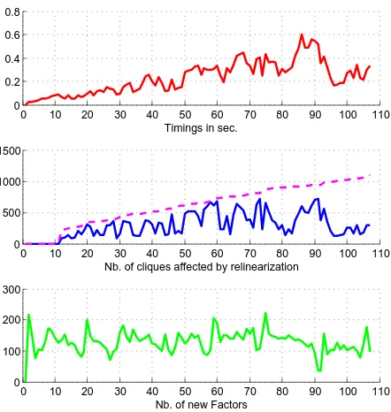
of the bundle adjustment that is always faster than 1 second on a 3.6 GHz machine, see Fig. 7. The required time is independent of the number of new factors added to the Bayes tree but rather highly depends on the number of cliques related to variables that need to be relinearized.
0 10 20 30 40 50 60 70 80 90 100 110 0
0.2 0.4 0.6 0.8
Timings in sec.
0 10 20 30 40 50 60 70 80 90 100 110 0
500 1000 1500
Nb. of cliques affected by relinearization
0 10 20 30 40 50 60 70 80 90 100 110 0
100 200 300
Nb. of new Factors
Figure 7: (a) Required time for processing incremental bundle adjustment using iSAM2. (b) Number of cliques related to re-linearized variables (solid) and the total number of cliques in the Bayes tree (dashed), note the effect on (a). (c) Number of new factors added, note that the number has no effect on (a).
The choice ofβhas a significant influence on the required time and the obtained accuracy of the estimated parameters. Set-tingβtoo low leads to relinearization of all variables on every keyframe and settingβtoo large decreases the accuracy of the estimates. As we expect to have better initial parameters with DGPS-observations, which will be included into the estimation process soon, the need for frequent relinearizations should de-crease.
The root mean square error (RMSE), which is determined after each incremental bundle adjustment, is in the order of 2–3, see Fig. 8, which is quite large as we assumed a standard deviation of
0 10 20 30 40 50 60 70 80 90 100 110 0
1 2 3 4
keyframe
RMSE
Figure 8: Root mean square error (RMSE) for each keyframe set.
σl= 1pixel for the extracted feature points. We apply the batch
bundle adjustment BACS on the observations used by iSAM2 and we use the estimated values of iSAM2 as approximates. We re-tain the pose of the first keyframe set to use the same gauge def-inition as we did using iSAM2. We obtain an empirical variance factor ofbσ2
0 = 2.0
2
which is quite large, being in the order of the RMSE. Applying the robust Huber minimizer shows no signifi-cant outliers and yields an equal robust empirical variance factor ofbσ2
0 = 1.96
2
. The reason for the poor accuracy of the observa-tions still has to be identified. It could lie e.g. in the tracking, in the assumption that the multi-camera system is rigid, not taking into account the possibility of vibrations, or a poor image quality. Differences in the estimated pose parameters between those from iSAM2 and BACS are shown in Fig. 9 for each set of keyframes. These differences are within their estimated uncertainty, shown in Fig. 10. The results show that iSAM2 provides estimates which are in a statistical sense optimal like the rigorous batch bundle adjustment BACS.
0 10 20 30 40 50 60 70 80 90 100 110
−0.04 −0.02 0 0.02 0.04
meter
translations
0 10 20 30 40 50 60 70 80 90 100 110
−0.1 −0.05 0 0.05 0.1
rotation angles
grad
x−axis y−axis z−axis
Figure 9: Deviations between the estimated rotation angles and translations of BACS and iSAM2 on all set of keyframes. The z-axis points in flight direction, the x-axis points upwards and the y-axis is orthogonal to both.
4 CONCLUSIONS AND FUTURE WORK
We presented our system for visual odometry performing a keyframe-based bundle adjustment for real-time structure and motion estimation in an unknown scene. Incremental bundle ad-justment is performed by using the iSAM2 algorithm for sparse nonlinear incremental optimization in combination with our mea-surement equations allowing for multi-view cameras, omnidirec-tional cameras and scene points at infinity. First experiments show the high potential of the incremental bundle adjustment w.r.t. time requirements and optimality.
0 10 20 30 40 50 60 70 80 90 100 110 0
0.02 0.04 0.06 0.08 0.1
meter
Estimated standard deviations of tranlsations
0 10 20 30 40 50 60 70 80 90 100 110
0.1 0.15 0.2 0.25 0.3 0.35
Estimated standard deviations of rotations
grad
x−axis y−axis z−axis
Figure 10: Estimated standard deviations of the estimated rota-tion angles and translarota-tions of BACS on all set of keyframes. All are up to the fourth digit identical to these provided by iSAM2. The axes are oriented as described in Fig. 9.
the issue of estimating scene points which are at first near to the camera system and as the camera system moves away lying nu-merically at infinity. Furthermore we are porting the prototype, which is mainly running in MATLAB, to a fast C++ implemen-tation.
Acknowledgements This work was supported by the DFG-Project FOR 1505 “Mapping on Demand”.
References
Abraham, S. and F¨orstner, W., 2005. Fish-Eye-Stereo Calibration and Epipolar Rectification. ISPRS J. of Photogrammetry & Remote Sensing 59(5), pp. 278–288.
Abraham, S. and Hau, T., 1997. Towards Autonomous High-Precision Calibration of Digital Cameras. In: Videometrics V, Proc. of SPIE Annual Meeting 3174, pp. 82–93.
Aliaga, D. G., 2001. Accurate Catadioptric Calibration for Real-time Pose Estimation of Room-size Environments. In: Inter-national Conference on Computer Vision, pp. 127–134.
Bouguet, J.-Y., 2000. Pyramidal Implementation of the Lucas Kanade Feature Tracker Description of the algorithm.
Choi, K. and Lee, I., 2012. A Sequential Aerial Triangulation Algorithm for Real-time Georeferencing of Image Sequences Acquired by an Airborne Multi-Sensor System. Remote Sens-ing 5(1), pp. 57–82.
Davison, A. J., 2003. Real-Time Simultaneous Localisation and Mapping with a Single Camera. In: ICCV ’03: Proceedings of the Ninth IEEE International Conference on Computer Vision, IEEE Computer Society, Washington, DC, USA, p. 1403.
Dellaert, F., 2012. Factor Graphs and GTSAM: A Hands-on In-troduction. Technical Report GT-RIM-CP&R-2012-002, GT RIM.
Engels, C., Stewenius, H. and Nister, D., 2006. Bundle Adjust-ment Rules. In: Int. Archives of Photogrammetry and Remote Sensing, pp. 266–271.
Golub, G. H. and Van Loan, C. F., 1996. Matrix Computations (3rd ed.). The Johns Hopkins University Press.
Gr¨un, A., 1984. Algorithmic Aspects in on-line Triangulation. In: Int. Arch. Photogramm. Remote Sens. Spatial Inf. Sci., Vol. XXV-A3, pp. 342–362.
Gr¨un, A., 1987. Towards real-time Photogrammetry. In: togrammetric Week 1987, Schriftenreihe des Instituts fr Pho-togrammetrie, Heft 12,.
Huber, P. J., 1981. Robust Statistics. John Wiley, New York.
Kaess, M. and Dellaert, F., 2006. Visual SLAM with a Multi-Camera Rig. Technical Report GIT-GVU-06-06, Georgia In-stitute of Technology.
Kaess, M., Ila, V., Roberts, R. and Dellaert, F., 2010. The Bayes Tree: An Algorithmic Foundation for Probabilistic Robot Mapping. In: Intl. Workshop on the Algorithmic Foundations of Robotics (WAFR), Singapore, pp. 157–173.
Kaess, M., Johannsson, H., Roberts, R., Ila, V., Leonard, J. and Dellaert, F., 2012. iSAM2: Incremental Smoothing and Map-ping Using the Bayes Tree. Intl. J. of Robotics Research, IJRR 31, pp. 217–236.
Kaess, M., Ranganathan, A. and Dellaert, F., 2008. iSAM: In-cremental Smoothing and Mapping. IEEE Trans. on Robotics (TRO) 24(6), pp. 1365–1378.
Klein, G. and Murray, D., 2007. Parallel Tracking and Mapping for Small AR Workspaces. In: Proc. Sixth IEEE and ACM In-ternational Symposium on Mixed and Augmented Reality (IS-MAR’07), Nara, Japan.
Maas, H., 1999. Image Sequence Based Automatic Multi-camera System Calibration Techniques. ISPRS J. of Photogrammetry & Remote Sensing 54(5-6), pp. 352–359.
Mostafa, M. and Schwarz, K., 2001. Digital image georeferenc-ing from a multiple camera system by gps/ins. ISPRS J. of Photogrammetry & Remote Sensing 56(1), pp. 1–12.
Mouragnon, E., Lhuillier, M., Dhome, M. and Dekeyser, F., 2009. Generic and Real-time Structure from Motion Using Lo-cal Bundle Adjustment. Image and Vision Computing 27(8), pp. 1178–1193.
Schneider, J. and F¨orstner, W., 2013. Bundle Adjustment and System Calibration with Points at Infinity for Omnidirectional Camera Systems. Z. f. Photogrammetrie, Fernerkundung und Geoinformation, Heft 4,.
Schneider, J., Schindler, F., L¨abe, T. and F¨orstner, W., 2012. Bun-dle Adjustment for Multi-camera Systems with Points at Infin-ity. In: ISPRS Ann. Photogramm. Remote Sens. and Spatial Inf. Sci., Vol. I-3, pp. 75–80.
Shi, J. and Tomasi, C., 1994. Good Features to Track. In: 9th IEEE Conference on Computer Vision and Pattern Recognition (CVPR’94), pp. 593–600.
Strasdat, H., Montiel, J. M. M. and Davison, A. J., 2012. Visual SLAM: Why filter? Image Vision Comput. 30(2), pp. 65–77.
S¨underhauf, N., Konolige, K., Lacroix, S. and Protzel, P., 2005. Visual Odometry Using Sparse Bundle Adjustment on an Au-tonomous Outdoor Vehicle. In: P. Levi, M. Schanz, R. Lafrenz and V. Avrutin (eds), Autonome Mobile Systeme 2005, Infor-matik aktuell, Springer Berlin Heidelberg, pp. 157–163.