Submission Date: 2015-02-12
Approval Date: 2015-03-13
Publication Date: 2016-03-24
External identifier of this OGC® document: http://www.opengis.net/doc/DP/gml-aviation-guidance/r1
Internal reference number of this OGC® document: 12-028r1
Category: OGC® Discussion Paper
Editor: OGC Aviation Domain Working Group
Use of Geography Markup Language (GML) for Aviation Data
Copyright notice
Copyright © 2016 Open Geospatial Consortium
To obtain additional rights of use, visit http://www.opengeospatial.org/legal/.
Warning
This document is not an OGC Standard. This document is an OGC Discussion Paper and is therefore not an official position of the OGC membership. It is distributed for review and comment. This document is subject to change without notice and may not be referred to as an OGC Standard. Further, an OGC Discussion Paper should not be referenced as required or mandatory technology in procurements.
License Agreement
Permission is hereby granted by the Open Geospatial Consortium, ("Licensor"), free of charge and subject to the terms set forth below, to any person obtaining a copy of this Intellectual Property and any associated documentation, to deal in the Intellectual Property without restriction (except as set forth below), including without limitation the rights to implement, use, copy, modify, merge, publish, distribute, and/or sublicense copies of the Intellectual Property, and to permit persons to whom the Intellectual Property is furnished to do so, provided that all copyright notices on the intellectual property are retained intact and that each person to whom the Intellectual Property is furnished agrees to the terms of this Agreement.
If you modify the Intellectual Property, all copies of the modified Intellectual Property must include, in addition to the above copyright notice, a notice that the Intellectual Property includes modifications that have not been approved or adopted by LICENSOR.
THIS LICENSE IS A COPYRIGHT LICENSE ONLY, AND DOES NOT CONVEY ANY RIGHTS UNDER ANY PATENTS THAT MAY BE IN FORCE ANYWHERE IN THE WORLD.
THE INTELLECTUAL PROPERTY IS PROVIDED "AS IS", WITHOUT WARRANTY OF ANY KIND, EXPRESS OR IMPLIED, INCLUDING BUT NOT LIMITED TO THE WARRANTIES OF MERCHANTABILITY, FITNESS FOR A PARTICULAR PURPOSE, AND NONINFRINGEMENT OF THIRD PARTY RIGHTS. THE COPYRIGHT HOLDER OR HOLDERS INCLUDED IN THIS NOTICE DO NOT WARRANT THAT THE FUNCTIONS CONTAINED IN THE INTELLECTUAL PROPERTY WILL MEET YOUR REQUIREMENTS OR THAT THE OPERATION OF THE INTELLECTUAL PROPERTY WILL BE UNINTERRUPTED OR ERROR FREE. ANY USE OF THE INTELLECTUAL PROPERTY SHALL BE MADE ENTIRELY AT THE USER’S OWN RISK. IN NO EVENT SHALL THE COPYRIGHT HOLDER OR ANY CONTRIBUTOR OF INTELLECTUAL PROPERTY RIGHTS TO THE INTELLECTUAL PROPERTY BE LIABLE FOR ANY CLAIM, OR ANY DIRECT, SPECIAL, INDIRECT OR CONSEQUENTIAL DAMAGES, OR ANY DAMAGES WHATSOEVER RESULTING FROM ANY ALLEGED INFRINGEMENT OR ANY LOSS OF USE, DATA OR PROFITS, WHETHER IN AN ACTION OF CONTRACT, NEGLIGENCE OR UNDER ANY OTHER LEGAL THEORY, ARISING OUT OF OR IN CONNECTION WITH THE IMPLEMENTATION, USE, COMMERCIALIZATION OR PERFORMANCE OF THIS INTELLECTUAL PROPERTY.
This license is effective until terminated. You may terminate it at any time by destroying the Intellectual Property together with all copies in any form. The license will also terminate if you fail to comply with any term or condition of this Agreement. Except as provided in the following sentence, no such termination of this license shall require the termination of any third party end-user sublicense to the Intellectual Property which is in force as of the date of notice of such termination. In addition, should the Intellectual Property, or the operation of the Intellectual Property, infringe, or in LICENSOR’s sole opinion be likely to infringe, any patent, copyright, trademark or other right of a third party, you agree that LICENSOR, in its sole discretion, may terminate this license without any compensation or liability to you, your licensees or any other party. You agree upon termination of any kind to destroy or cause to be destroyed the Intellectual Property together with all copies in any form, whether held by you or by any third party.
Contents
1. Scope ... 12
2. Conformance ... 12
3. References ... 12
4. Terms and Definitions ... 12
4.1. data set ... 13
4.2. right-handed CRS ... 13
4.3. left-handed CRS ... 13
5. Conventions ... 13
5.1. Abbreviated terms ... 13
6. Coordinate reference systems ... 15
6.1. Geographic vs geometric data ... 15
6.2. CRS and srsName ... 16
6.3. WGS-84 ... 17
6.4. Use of global srsName ... 18
7. Positions ... 20
7.1. Background ... 20
7.2. GML encoding ... 20
8. Lines and Surfaces ... 21
8.1. Background ... 21
8.2. GML encoding ... 21
8.2.1. Straight lines ... 21
8.2.2. Parallels ... 22
8.2.3. Arc by edge ... 24
8.2.6. Perimeter encoding direction ... 31
8.2.7. Corridor ... 32
8.2.8. Other geometries ... 33
9. Airspace aggregation ... 35
9.1. Background ... 35
9.2. GML encoding ... 35
9.2.1. By reference ... 35
9.2.2. By copying the geometry ... 38
9.2.3. Combined method ... 40
10. Point references and annotations ... 41
10.1. Background ... 41
10.2. GML encoding ... 42
10.2.1. Using aixm:Point annotations ... 42
10.2.2. Using xlink:href ... 43
10.2.3. Summary ... 44
11. Geographical border references ... 45
11.1. Background ... 45
11.2. GML encoding ... 46
11.2.1. Using aixm:Curve annotations ... 46
11.2.2. Using xlink:href ... 48
12. AIXM GML Profile ... 54
12.1. Introduction ... 54
12.2. Purpose of the profile ... 54
12.3. Scope of the profile ... 54
12.4. Using the AIXM GML Profile ... 55
12.5. XML Namespaces ... 55
12.6.1. Basic Types ... 55
12.6.2. AIXM Types ... 57
12.6.3. ISO 19107 and ISO 19136 (GML) Types - Overview ... 57
12.6.4. ISO 19108 and ISO 19136 (GML) Types ... 61
12.6.5. Use of xsi:type is forbidden ... 63
12.7. AIXM GML Profile Definition ... 65
Annex A - List of CRS used for aeronautical data ... 67
Left-handed CRS ... 67
Right-handed CRS ... 68
Annex B - ArcByCenterPoint Interpretation Summary ... 69
Introduction ... 69
Angle Measuring Convention in GML ... 69
General Direction of Increasing and Decreasing Angle Values ... 69
Angle Measurement in Different Coordinate Systems ... 70
Direction of an Arc ... 71
Arc encoding examples in a left-handed CRS system ... 72
Arc interpolation ... 76
Annex C - Mapping for ArcByCenterPoint ... 77
Annex D - Perimeter encoding direction considerations ... 80
Annex E – Offset Curve and Airspace Corridor encoding issues ... 82
Annex F – Considerations about interpolations ... 85
Role of interpolation ... 85
Why geodesic is better ... 85
Practical considerations ... 86
Mapping of GML to Simple Geometry ... 88
Flattening of geometry structure ... 88
Densification of curves ... 88
Loss of data structure ... 89
Annex G - GML Profile - XML Schema Implementation ... 90
AIXM Point – Documentation ... 90
AIXM ElevatedPoint – Documentation ... 91
AIXM Curve – Documentation ... 92
AIXM ElevatedCurve – Documentation ... 93
AIXM Surface – Documentation ... 95
AIXM ElevatedSurface – Documentation ... 96
DirectPosition / gml:pos – Documentation ... 98
GM_Object / gml:AbstractGeometry – Documentation ... 98
GM_Point / gml:Point – Documentation ... 100
GM_Envelope / gml:Envelope – Documentation ... 101
GM_PointRef / gml:pointProperty – Documentation ... 102
GM_Position / gml:geometricPositionGroup – Documentation ... 102
GM_PointArray / gml:posList – Documentation ... 103
gml:AbstractCurve – Documentation ... 104
GM_Curve / gml:Curve – Documentation ... 105
GM_CurveSegment / gml:AbstractCurveSegment – Documentation ... 106
gml:ArcByCenterPoint – Documentation ... 107
gml:CircleByCenterPoint – Documentation ... 109
GM_Arc / gml:Arc – Documentation ... 111
GM_Circle / gml:Circle – Documentation ... 112
GM_GeodesicString / gml:GeodesicString – Documentation ... 113
GM_LineString / gml:LineStringSegment – Documentation ... 115
GM_Surface / gml:Surface – Documentation ... 116
GM_SurfacePatch / gml:AbstractSurfacePatch – Documentation ... 117
GM_Polygon / gml:PolygonPatch – Documentation ... 118
gml:AbstractRing – Documentation ... 119
GM_Ring / gml:Ring – Documentation ... 119
GM_OrientableCurve / gml:OrientableCurve – Documentation ... 121
GM_CompositeCurve / gml:CompositeCurve – Documentation ... 123
TM_GeometricPrimitive / gml:AbstractTimeGeometricPrimitive – Documentation .... 124
TM_Instant / gml:TimeInstant – Documentation ... 125
TM_Period / gml:TimePeriod – Documentation ... 126
GML Simple Types ... 127
Deprecated GML 3.2.1 items ... 127
i.
Abstract
Starting with version 5, the Aeronautical Information Exchange Model (AIXM) schema began using the OGC Geographical Markup Language (GML) version 3.2.1 for the encoding of positional and shape data of aeronautical information items, such as airspace, runway thresholds, navaids, etc.
The ISO 19107 spatial schema, which is implemented in GML, is very complex. ISO 19107 contains an extensive list of geometries, geometric properties and operations – many of which are not necessary for aeronautical information applications. In addition, ISO 19107 contains an exhaustive 3D geometry model that is probably not needed in its entirety for AIXM either. Therefore, a profile of GML for AIXM needs to be defined.
The objective of this document is to identify the elements of the AIXM-GML profile and to provide guidelines for the use of GML constructs in AIXM data sets.
ii.
Keywords
The following are keywords to be used by search engines and document catalogues.
ogcdoc, OGC document, GML, AIXM, aviation profile
iii.
Preface
According to the ICAO1 rules, Aeronautical Information (AI) is published by States using paper (and increasingly electronic) documents, such as Aeronautical Information Publications (AIP), charts, manuals. These data includes geographically related information items such as:
▪ Positions expressed in latitude/longitude, which according to ICAO Annex 15 shall use a WGS-84 datum;
▪ Shapes of airspace, expressed as a series of positions in combination with arcs of circles or as full circles. Sometimes, these shapes contain references to national borders, water courses, etc., which are not provided explicitly in the AIP;
▪ Shapes of obstacles, provided as point, line or polygon, again using a series of positions and arcs of circle.
Since 2003, the Aeronautical Information Exchange Model (AIXM) has been used for the provision of AI in digital format. Initially developed for the European AIS Database, AIXM was progressively adopted by other States world-wide. From the International Civil Aviation
Organisation (ICAO) perspective, AIXM is positioned as a means of achieving compliance with the standards and recommended practices for digital aeronautical data exchange, as stated in the ICAO Annex 15.
AIXM versions up to 4.5 used a custom XML encoding and did not use OGC standards. Beginning in 2008 with the publication of version 5, the AIXM specification has embraced GML as the data encoding format.
There are a number of specific requirements in the AI Domain that concern the provision of geographical and geometrical information. These requirements are discussed in this document and includes recommendations for data encoding in GML.
The first version of this document was developed by the OGC Aviation Domain Working Group and published as an OGC Discussion Paper (OGC document reference 12-028) in May 2012. This version is an update of the original version and based on the feedback from users and the results for OGC testbed activities provides further guidance and clarifications.
The objective is the publication of this document as an OGC Best Practice document by mid-2015
iv.
Forward
Attention is drawn to the possibility that some of the elements of this document may be the subject of patent rights. The Open Geospatial Consortium shall not be held responsible for identifying any or all such patent rights.
v.
Submitting organizations
The following organizations submitted this Document to the Open Geospatial Consortium (OGC):
● IDS Ingegneria Dei Sistemi S.p.A.
● Interactive Instruments
● Luciad
● M-click
● Snowflake Software
● SOLITEC Software Solutions GesmbH
● Thales
vi.
Submitters
All questions regarding this submission should be directed to the editor or the contributors:
Name Role Organization
Daniel Balog Contributor Luciad
Manfred Beckmann Contributor SOLITEC Software Solutions GesmbH
David Burggraf Contributor Galdos, Inc.
Eddie Curtis Contributor Snowflake Software
Warwick Dufour Contributor Avitech AG
Johannes Echterhoff Editor interactive instruments
Yves Ernotte Contributor Thales
Davide Castagni Fabbri Contributor IDS Ingegneria Dei Sistemi S.p.A
Benoit Geffroy Contributor EgisAvia
Francois Germain Contributor Thales
Volker Grabsch Contributor M-Click
Razvan Guleac Contributor EUROCONTROL
Robin Houtmeyers Contributor Luciad
Alain Kabamba Contributor Erdas
Michal Kadlec Contributor Avitech AG
Ian Painter Contributor Snowflake Software
Eduard Porosnicu Editor EUROCONTROL
Bert Robben Contributor Luciad
Timo Thomas Contributor Comsoft
Scott Wilson Contributor EUROCONTROL
1.
Scope
The document provides guidelines for the use of GML and a GML profile description in the scope of aeronautical data encoding, in particular when using the Aeronautical Information Exchange Model (AIXM). In the future, the applicability of the guidelines contained in this document might be enlarged to cover other related domains, such as aeronautical weather data and flight data.
2.
Conformance
This document is aimed at becoming an OGC Best Practice. Compliance with this best practice implies compliance with all the "shall" statements contained in this document.
For a particular AIXM data set, conformance with the provisions of this document shall be declared through the inclusion of the following annotation in the AIXM Schema file:
<annotation> <appinfo>
<gml:gmlProfileSchema>http://www.aixm.aero/schema/GML_profile/gml321forAIXM.xsd </gml:gmlProfileSchema>
</appinfo> </annotation>
3.
References
The following normative documents contain provisions that, through reference in this text, constitute provisions of this document. For dated references, subsequent amendments to, or revisions of, any of these publications do not apply. For undated references, the latest edition of the normative document referred to applies.
● ISO 19107:2003 – Geographic information — Spatial schema
● ISO 19136:2007 – Geography Markup Language
● OGC 07-092r3 - Definition identifier URNs in OGC namespace http://portal.opengeospatial.org/files/?artifact_id=30575
● OGC 06-042 - OpenGIS® Web Map Server Implementation Specification http://portal.opengeospatial.org/files/?artifact_id=14416
● ISO 19108:2002 - Geographic information - Temporal schema
4.
Terms and Definitions
For the purposes of this document, the following additional terms and definitions apply.
4.1. data set
Means an identifiable collection of data.
4.2. right-handed CRS
The name derives from the right-hand rule (mathematics and physics). If the index finger of the right hand is pointed forward, the middle finger bent inward at a right angle to it, and the thumb placed at a right angle to both, the three fingers indicate the relative directions of the x-, y-, and z-axes in a right-handed system. The thumb indicates the x-axis, the index finger the y-axis and the middle finger the z-axis. Conversely, if the same is done with the left hand, a left-handed system results.
Figure 1 - Left-handed and right-handed systems
When applied to a geodetic Coordinate Reference System (CRS) for which the z axis points from the centre of the Earth outwards, this implies that right-handed systems will have longitude (East) as first axis and latitude (North) as second axis. This is not the usual aviation convention, as latitude is usually used in aviation as first axis and angles/bearings are measured clockwise towards East (the second axis).
4.3. left-handed CRS
See the explanations for right-handed CRS above. Left-handed CRS are the natural choice for the aeronautical data domain.
5.
Conventions
This sections provides details and examples for any conventions used in the document. Examples of conventions are symbols, abbreviations, use of XML schema, or special notes regarding how to read the document.
5.1. Abbreviated terms
Table 1 - abbreviations
AIP Aeronautical Information Publications
AIXM Aeronautical Information Exchange Model
EPSG European Petroleum Survey Group
GIS Geographic Information System
GML Geographical Markup Language
ISO International Organization for Standardization
OGC Open Geospatial Consortium
OPADD Operating Procedures for Aeronautical Dynamic Data
UCUM Unified Code of Units of Measure
6.
Coordinate reference systems
6.1. Geographic vs geometric data
As in many other classes of applications, aeronautical applications deal with entities which have a geographic extent. By definition, software systems supporting aeronautical applications are Geographic Information Systems (GIS). Within this context, distinguishing between the adjectives “geometric” and “geographic” is worthwhile.
Geometric entities are point sets in a metric space, namely a topological space endowed with a metric. A metric is nothing but a set of rules for measuring space properties such as distances, angles, volumes and so on. A well known example of metric space is n-dimensional Euclidean space , namely the real vector space endowed with the usual Euclidean metric (where the distance between any two points is given by the Pythagorean formula applied to the points’ coordinates).
Geographic entities are geometric entities belonging not to a generic, abstract metric space but to the Euclidean 3D space surrounding the Earth, where the metric can be operatively defined by means of the usual measuring processes, once a length unit of measure has been defined, such as “meters”. This metric is the Euclidean-Pythagorean one for Earth Centered Earth Fixed (ECEF) coordinates.
Given that a great part of the physical phenomena relevant for GIS applications is restricted to a thin layer of space surrounding the Earth surface, it is often useful to adopt a Coordinate Reference System (CRS) different from ECEF. Therefore, in many applications, including those in the aeronautical family, it is common to adopt a CRS in which the first two coordinates parameterize the Earth surface while the third coordinate parameterizes the orthogonal axis emanating from the surface. The third coordinate is called altitude or height, depending on the zero reference point (e.g. ellipsoid, geoid or terrain).
In many applications the horizontal aspect of geographic entities is far more relevant than the vertical aspect. Hence geographic entities are simply described as 2D geometric objects: the orthogonal projection of 3D entities onto the Earth surface.
6.2. CRS and srsName
In GML, the geodetic datum is specified by reference to a Coordinate Reference System (CRS). A CRS relates a coordinate system to the Earth by a datum. A geodetic datum consists of an ellipsoid model and a prime meridian. The intersection of the equator and prime meridian is the origin of the CRS.
Figure 2 - ECEF coordinate system
A geodetic CRS (e.g. EPSG 4326) relates a (lat/long) ellipsoidal coordinate system to the Earth.
Figure 3 - Ellipsoidal coordinate system
The CRS reference is critical for the correct encoding and processing of the geographical data contained in AIXM/GML files. The CRS indicates not only the geodetic reference datum, but also the order of the coordinate axes (latitude/longitude or longitude/latitude) and has important implications for the convention used for measuring angles (from the North, clockwise, for example). This will be discussed in more detail later in this document.
OGC. The two sets of CRS definitions have many common points. For example, the OGC:CRS84 is a variant of EPSG:4326 (differing only in its coordinate order: longitude/latitude) and is defined in the ISO 19128 Geographic information — Web Map Server standard. The EPSG CRS database is available at http://www.epsg.org - European Petroleum Survey Group Geodesy Parameters [EPSG CRS].
Recommendations for the use of CRS references in GML data sets are provided in the OGC Recommendation Paper “URNs of definitions in ogc namespace” [OGC 07-092r3]. The CRS of an AIXM geometry is identified by a URN (e.g. urn:ogc:def:crs:EPSG::4326) and defined in its srsName attribute or derived from the larger context that the geometry is part of.
When applied to the encoding of a surface in AIXM, this will give the following GML element:
<aixm:Surface gml:id="S01" srsName="urn:ogc:def:crs:EPSG::4326">
Specifying the srsDimension attribute is not required. This is because it is implicit in the srsName. Specifying the srsDimension could lead to discrepancies, such as using srsName=”epsg:4326” and srsDimension=”3”. One could think that this is a good way to describe 3D WGS84 coordinates. However, this assumption is wrong and an appropriate 3D srsName should be used in that case, such as EPSG::4979.
6.3. WGS-84
According to ICAO Annex 15, all “published aeronautical geographical coordinates (indicating latitude and longitude) shall be expressed in terms of the WGS-84 geodetic reference datum”.
The Coordinate Reference System (CRS) reference is critical for the correct encoding and processing of AIXM/GML geometries. This is because a CRS not only indicates the geodetic datum and ellipsoid for which point coordinates are expressed but also the order of the coordinate axes in which coordinate values are provided, e.g. latitude before longitude – which is an important convention for the aviation domain.
Due to the way that angle directions are traditionally measured in the AI domain (North corresponds to 0°, East to 90°, etc.), the use of the OGC:CRS 84 is not straight-forward for AIXM 5.1/GML data sets that contain arcs of circle defined by start angle/end angle measured from the North. This will be explained in section "Measuring angles in GML"of this document. Therefore, the EPSG:4326 CRS is the typical choice for AIXM 5.1 data sets that use the WGS-84 reference datum. However, this does not exclude the use of other CRS when appropriate.
When encoding aeronautical data that complies with the WGS-84 ICAO Standard, the following Coordinate Reference System (CRS) shall be used in AIXM 5.1:
● EPSG:4326 - for data conforming to the usual aviation practice (latitude first, longitude second, angles/bearings measured from the North with positive values clockwise);
When encoding aeronautical data that does not comply with the WGS-84 ICAO Standard an appropriate CRS shall be used. A list of CRS that are likely to be used in aeronautical data sets is provided in Annex A of this document. The use of other CRS falls outside the scope of this document.
Geographic coordinates(latitude and longitude) shall be expressed in decimal degrees, not in degrees minutes seconds.
6.4. Use of global srsName
For all geometries (Surface, ElevatedPoint, etc.) a CRS shall be specified. The CRS is either defined directly on the geometry element using the srsName attribute or is derived from the larger context the geometry is part of.
Unless overruled by the presence of a local srsName for convenience in constructing feature and feature collection instances, the value of the srsName attribute on the gml:Envelope shall be inherited by all directly expressed geometries in all properties of the feature or members of the collection. As indicated in Figure 4, the gml:Envelope is a child element of the gml:boundedBy property of the feature. If a geometry uses the same coordinate reference system as given on the gml:boundedBy property of its parent feature that geometry does not require a srsName attribute,
Inheritance of the coordinate reference system continues to any depth of nesting. However, if overruled by a local srsName declaration, then the new coordinate reference system is inherited by all its children in turn.
Notwithstanding this rule, all the geometries used in a feature or feature collection may carry srsName attributes. This is in order to indicate a local reference system, even if they are the same as the parent. A geometry without a srsName derives its CRS from its closest ancestor that has a srsName. Due to the way that AIXM is modelled, this can only be one of the following:
▪ aixm:Surface ▪ aixm:Curve ▪ aixm:Point
7.
Positions
7.1. Background
Simple positions are used in order to indicate the geographical location of an airport reference point, navaid, waypoint, runway threshold, etc. In AI publications, simple positions are expressed as a pair of latitude/longitude coordinates. Usually the information about the geodetic reference datum is specified once for the whole AIP and not provided for each individual position.
7.2. GML encoding
In AIXM 5.1, simple positions are encoded using the aixm:Point or aixm:ElevatedPoint elements, which are extensions of the gml:Point:
…
<aixm:ElevatedPoint srsName="urn:ogc:def:crs:EPSG::4326" gml:id="ID55">
<gml:pos>52.2889 -32.0350</gml:pos>
</aixm:ElevatedPoint> …
Note that the EPSG:4326 CRS has latitude as the primary axis, which indicates that the order of the values in the gml:pos element is first latitude, then longitude. This convention is very important for the correct interpretation of the data and it is not the same for all CRS! For example, the OGC:CRS84 has longitude as the primary axis. Therefore in a GML data set that use the OGC:CRS84 the first value in the gml:pos element will indicate the longitude!
The convention “first latitude, then longitude” is widely observed in the AI domain. Not surprisingly, the OGC WMS standard has a note that reads: “users in the international aviation and marine sectors may expect latitude to be before longitude, and a different coordinate display may have safety implications, especially in an emergency response situation” and “developers of user interfaces for WMSs are cautioned that all references to latitude and longitude, for example user input of bounding box or readout of cursor coordinates, should show latitude before longitude”.
8.
Lines and Surfaces
8.1. Background
Certain features in the AI domain have polygonal shapes (such as Airspace) or linear shapes (such as a power line Vertical Structure). They are typically published (for example, in Aeronautical Information Publications – AIP) as a series of latitude/longitude positions, such as in the following example:
EAP 25 (The Castle) 521108.00N 0051230.00E; 521222.00N 0051715.00E; 521121.00N 0051756.00E;
521009.00N 0051756.00E;
(then along the parallel to) 521009.00N 0051311.00E; to point of origin.
Usually, the interpolation method used for the curve between the consecutive points it is not indicated in the AI source documents , but it is generally assumed that:
▪ If two consecutive points have the same latitude value, then the line connecting the two points is a parallel on the surface of the Earth; this may be explicitly stated using words such as “along the parallel to”;
▪ Otherwise, it is considered a “straight line on the map”.
In addition, the source map used when the airspace was designed is typically unknown.
Arcs of circle are also used in the definition of airspace borders, such as in the following examples:
EHR 4A (VLIEHORS) TSA
531012.59N 0044621.14E; along clockwise arc (radius 8 NM, centre 531500.00N 0045700.00E) to 530701.98N 0045602.41E; 531100.00N 0045124.00E; to point of origin.
EHR 4B (VLIEHORS)
530943.06N 0050658.79E; 530240.00N 0051500.00E; 525809.00N 0050622.00E; 530701.98N 0045602.41E; along anti-clockwise arc (radius 8 NM, centre 531500.00N 0045700.00E) to point of origin.
Arcs may also be used in the definition of approach/departure trajectories. However, specific “path and terminator” codes are used to encode such arcs and the use of GML in this case is limited to providing a curve for printing the procedure on a map. GML is not used to encode the real flight trajectory of an aircraft, as stored in the Flight Management System (FMS).
▪ A geodesic interpolation is the mathematical generalization of the notion of “straight line” on the surface of the Earth;
▪ The result of the interpolation on the surface of the Earth does not depend on the CRS used; by contrast, a linear interpolation would result on different curves on the surface of the Earth, depending on the CRS used (in fact, this will be exploited in order to encode lines along a parallel, see further down).
Surfaces are encoded in GML using gml:PolygonPatch elements. The pairs of lat/long coordinates can be encoded as either a sequence of gml:pos or, more compact, using a gml:posList element:
…
<aixm:Surface gml:id="S01" srsName="urn:ogc:def:crs:EPSG::4326"> <gml:patches>
<gml:posList>52.18556 5.20833 52.20611 5.2875 52.18917 5.29889 52.16917 5.29889 52.18556 5.20833</gml:posList>
</gml:GeodesicString>
Note that the first latitude/longitude pair in this posList example is equal to the last one. As stated in section 10.5.11.1 of the GML Standard: “Every gml:curveMember references or contains one curve, i.e. any element which is substitutable for gml:AbstractCurve. In the context of a ring, the curves describe the boundary of the surface. The sequence of curves shall be contiguous and connected in a cycle”. In the special case that there is only one curve member in a gml:Ring, this means that the curve member itself needs to form a cycle, thus the need for the last position to be equal with the first one. Note that in GML 3.3 there are new compact encodings for geometry primitives, such as SimplePolygon that do not require the repeated last coordinate. However, these are not available yet in AIXM 5.1, which uses GML 3.2.1.
Also note that the same separator (space) is used both between the latitude and longitude values (coordinate separator) and also between the latitude/longitude groups (tuple separator).
8.2.2. Parallels
such as EPSG:4326. The linear interpolation in a 2D geodetic CRS between two points that have the same latitude corresponds to a parallel on the Earth’s surface. This is shown graphically in Figure 5.
Figure 5 - Linear interpolation in a geodetic CRS
Note that the current GML 3.2.1 does not allow general “rhumbline” (constant angle with the meridians) interpolations to be specified directly (e.g. using a “RhumbLine” element or a “rhumbline” interpolation). However, linear interpolations in certain conformal projections do correspond to rhumblines on the ellipsoid Earth model.
For example, a LineStringSegment with two coordinates (i.e. a line segment with begin and end point) may be used with a srsName that references a Mercator projection (e.g. EPSG:3395), which is a well supported conformal projection. Note that the LineStringSegment element implies that linear interpolation must be used and srsName=”urn:ogc:def:crs: EPSG::3395” implies that the interpolation is done in the Mercator projection plane. Hence this geometry gets realized as a rhumbline on the WGS84 ellipsoid Earth model. Other conformal stereographic and conical projections can also be used to represent rhumblines on the earth ellipsoid model of WGS84 (this may be useful for regions of interest near the poles).
In conclusion:
▪ in the classical aeronautical information case of two consecutive points having the same latitude, a gml:LineStringSegment with "default" CRS EPSG:4326 shall be used for encoding. This is the case for most Airspace data published by States.
▪ in the particular case where one wants to express a rhumbline whereas the two consecutive latitudes are different, a gml:LineStringSegment with a "Mercator" CRS like EPSG:3395 may be used. However, this is a theoretical discussion since no real world aeronautical data like is known to require the use of arbitrary rhumblines.
8.2.3. Arc by edge
This is a relatively simple case as it is represented by the element gml:Arc in GML, which does not have any ambiguities: 3 points always define a single arc. Unfortunately, this is rarely used in the AI domain. When moving towards a fully digital AI chain, the use of this type of arc information should be encouraged and eventually imposed as the unique way for defining arcs. However, this is not likely to be achieved on short term.
A border that uses arcs by 3 points looks like in Figure 6 - Arc by edge point:
Figure 6 - Arc by edge point
A GML encoding example for this type of arcs is provided below.
…
<gml:PolygonPatch> <gml:exterior>
<gml:Ring gml:id=”…”>
…
<gml:curveMember> <gml:Curve gml:id="…"> <gml:segments> <gml:Arc gml:id=”…”> <gml:pos>P2</gml:pos> <gml:pos>P3</gml:pos> <gml:pos>P4</gml:pos> </gml:Arc>
</gml:segments> </gml:Curve> </gml:curveMember> ...
In fact, this is a particular case of the more general GML concept of “ArcString”2, which is a curve segment that uses three-point circular arc interpolation in a piecewise fashion to “string” the arc segments together. The number of control points in the string is (2 x numArc)+1, where
2
numArc is the property defining the number of the arcs in the string, such as in Figure 7 - ArcString in ISO 19107.
Figure 7 - ArcString in ISO 19107
8.2.4. Arc by centre point
Although this is the typical construct for arcs used in the definition of airspace borders in the AI domain, it is recommended to avoid, as much as possible, the use of arcs by centre points. It comes with two problems:
▪ The arc is over specified, as the start/end points, the centre and the radius are all provided. Typically, the calculated distance from the centre to the start and end point is not quite the same due to round-off error and is also usually different from the radius;
▪ This construction of arcs is not supported exactly this way in GML and in GIS systems in general.
The closest GML construct that can be used for encoding this type of arcs is ArcByCenterPoint. This requires calculating the start/end angles from the centre to the start/end points. Before calculating these angles, it is important to specify the angle measuring convention in AIXM, as GML seems to leave some degree of interpretation for this aspect.
8.2.4.1. Measuring angles in GML
in Section 6.3.12, which states that “Bearing is a data type used to represent direction in the coordinate reference system. In a 2D coordinate reference system, this can be accomplished using a “angle measured from true north” or a 2D vector point in that direction.”
There are two variants mentioned in ISO 19107 for expressing bearings: angle and direction. The semantics for angle is given in 6.3.12.2 of the same document: “In this variant of Bearing usually used for 2D coordinate systems, the first angle (azimuth) is measured from the first coordinate axis (usually north) in a counterclockwise fashion parallel to the reference surface tangent plane.”
Although it may not be obvious, this definition matches the needs of the AI domain, as angles are usually expressed in degrees measured clockwise from the True North. The diagrams below explain why the “counter clockwise” convention stated in the ISO 19107 standard, when combined with left-handed geodetic CRS actually corresponds to a clockwise rotation in the AI domain.
Figure 8 - Angle measured in a 2D geodetic CRS that has latitude as first axis
In the EPSG:4326 CRS, the first (x) axis is latitude and the second (y) axis is longitude. A counter clockwise angle means measuring it from the first axis towards the second axis. When transposing this coordinate system on the surface of the Earth, this corresponds to a clockwise rotation from the first axis (North) in order to measure angles, as shown in Figure 9. Practically, the x/y reference system is mirrored and rotated to be aligned with the meridians and the parallels.
Figure 9 - Coordinate System Axes of EPSG:4326 CRS mapped on the Earth's surface
Therefore, when the EPSG:4326 CRS (or another 2D geodetic CRS that has latitude as first axis) is used, this translates to angles that are measured clockwise starting from the True North in the AI Domain. East is at 90 degrees from North, South at 180 degrees from North, etc. This convention is important for defining the startAngle and endAngle of the ArcByCenterPoint. Note that it is also possible to use negative values for angles. Negative angles are measured from the first axis through rotation in the direction opposite to the second axis.
The following diagram shows how angles are measured in WGS 84 2D with different coordinate systems:
Figure 10 - Measuring angles in WGS 84 2D for different coordinate systems
(A) GeodeticCRS: urn:ogc:def:crs:OGC:1.3:CRS84 (right-handed) ● Datum: WGS84
● Ellipsoidal 2D CS.
o Axes: (1st) longitude, (2nd) latitude.
● Ellipsoidal 2D CS.
o Axes: (1st) latitude, (2nd) longitude.
o Orientations: north, east. UoM: degree
The order of the axes determines where 0° is located (on the positive part of the coordinate system's first axis).
8.2.4.2. Arc direction
Once the startAngle and endAngle are known, it is still necessary to establish how the arcs are interpolated/drawn. The semantics of the words “start” and “end” indicate that arcs shall be interpolated/drawn from the start angle to the end angle, similarly to a line that is always interpolated/drawn from its start to its end. However, this still leaves some room for interpretation, e.g. an arc that has startAngle=90 (East) and endAngle=180 (West) should be interpolated/drawn through South or through North?
The following convention shall apply in the aviation domain: if the start angle is smaller than the end angle then the arc direction is the direction in which the angle values increase. If the opposite is true, then the arc direction is the one in which the angle values decrease. Depending upon the coordinate system that applies to a given ArcByCenterPoint, this results in a clockwise (left-handed system) or counter-clockwise (right-handed system) directed arc. The arguments for this convention are detailed in Annex B.
Applied with the EPSG:4326 CRS, this means that arcs are drawn:
▪ clockwise on the surface of the Earth when the startAngle is smaller than the endAngle;
▪ counter-clockwise on the surface of the Earth when the startAngle is larger than the endAngle
Figure 11 - Arcs are drawn from startAngle to endAngle
Applied with the CRS:84 CRS, this means that arcs are drawn:
▪ counter-clockwise on the surface of the Earth when the startAngle is smaller than the endAngle;
▪ clockwise on the surface of the Earth when the startAngle is larger than the endAngle
An example of the GML encoding for an ArcByCenterPoint is presented below. …
<aixm:Surface gml:id="S01" srsName="urn:ogc:def:crs:EPSG::4326"> <gml:patches>
<gml:PolygonPatch> <gml:exterior>
<gml:Ring>
<gml:curveMember>
<aixm:Curve gml:id="C01"> <gml:segments>
<gml:GeodesicString>
<gml:posList>lat_Px long_Px lat_Py long_Py</gml:posList> </gml: GeodesicString>
<gml:ArcByCenterPoint gml:id="A01"> <gml:pos>lat_Pc long_Pc</gml:pos> <gml:radius uom="m">radius</gml:radius>
<gml:startAngle uom="deg">calculated_start_angle</gml:startAngle> <gml:endAngle uom="deg">calculated_end_angle</gml:endAngle> </gml:ArcByCenterPoint>
<gml:GeodesicString>
<gml:posList>lat_Pz long_Pz lat_Pw long_Pw</gml:posList> </gml:GeodesicString>
…
</gml:Ring>
8.2.4.3. Units of measurement
The previous XML encoding example also shows recommended values for the uom attributes of gml:radius and gml:start(end)Angle. According to GML section 8.2.3.7, “in an instance document, on elements of type gml:MeasureType the mandatory uom attribute shall carry a value corresponding to either:
▪ a conventional unit of measure symbol,
▪ a link to a definition of a unit of measure that does not have a conventional symbol, or when it is desired to indicate a precise or variant definition.
For common units of measurement, such as meter for distances and degrees for angles, conventional units of measure symbols shall be used. A Note in the [GML] standard suggests the use of UCUM symbols: “It is recommended that the symbol be an identifier for a unit of measure as specified in the Unified Code of Units of Measure’ (UCUM) [9]. This provides a set of symbols and a grammar for constructing identifiers for units of measure that are unique, and may be easily entered with a keyboard supporting the limited character set known as 7-bit ASCII.”
The following UCUM “c/s” (case sensitive) values shall be used for gml:radius in AIXM/GML data sets:
▪ m – when the radius is expressed in meters ▪ km – when the radius is expressed in kilometers
▪ [nmi_i] – when the radius is expressed in Nautical Miles
The symbol “deg” shall be used for the uom attribute of gml:startAngle and gml:endAngle elements.
8.2.5. Circle by center point
Full circles are also used in order to define the geometry of certain airspace in the AI domain. They can be directly encoded using the gml:CircleByCenterPoint. It is quite deep in the structure, as presented in the example below.
…
<aixm:Surface gml:id="S001" srsName="urn:ogc:def:crs:EPSG::4326"> <gml:polygonPatches>
<gml:PolygonPatch> <gml:exterior> <gml:Ring>
<gml:curveMember>
<gml:CircleByCenterPoint numArc="1">
<gml:pos>51.01555556 2.57138889</gml:pos> <gml:radius uom="[nmi_i]">12</gml:radius> </gml:CircleByCenterPoint>
</gml:segments> </gml:Curve> </gml:curveMember> </gml:Ring>
</gml:exterior> </gml:PolygonPatch> </gml:polygonPatches> </aixm:Surface>
…
Note that CircleByCenterPoint should be used only to define a simple circular airspace boundary and it should appear as unique member of a gml:Curve. Otherwise, the orientation of the circle boundary is not well defined.
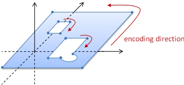
8.2.6. Perimeter encoding direction
The GML Surface implements ISO 19107 GM_Surface whose exterior boundary shall be encoded counter-clockwise and any interior boundary encoded clockwise.
Figure 12 - Encoding direction for surface boundaries
For aeronautical data, this implies that the outside perimeter and any eventual holes shall be encoded as shown in Figure 12. This rule might be difficult to apply strictly on short term as existing aeronautical systems require data to be encoded in clockwise direction. For example, the Operating Procedures for Aeronautical Dynamic Data (OPADD), version 3.0, indicates in 2.3.22.12 that “points defining lateral limits of an area should be enumerated in clockwise order”. Further details can be found in Annex D.
rule and application developers shall be aware of this exception. As the use of GML internal patches (rings) is not supported by this profile, non-compliance with this rule is not expected to have practical consequences. Existing GIS software often is rather lenient when it comes to this rule and often ignores it.
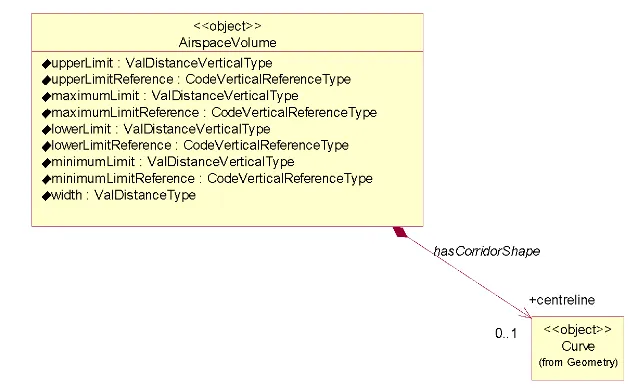
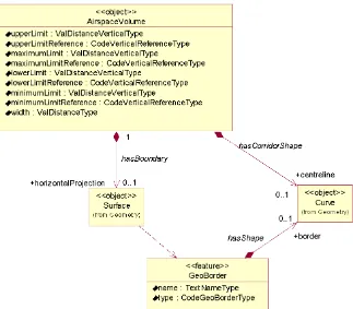
8.2.7. Corridor
Corridors are sometimes used in the definition of airspace geometries. This is done by specifying a centerline and a width or half-width and it is supported in AIXM through the following properties of the AirspaceVolume class:
▪ “width” attribute
▪ “centreline” association with Curve
Figure 13 - Corridors defined as AirspaceVolume having a “centreline”association with Curve
8.2.8. Other geometries
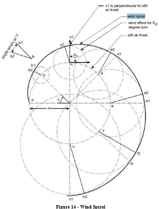
Some specific geometrical constructs are used in the design of instrument approach/departure procedures and in the design of route segments in the AI domain. They are mentioned in this section for completeness sake. More details about their encoding in GML might be provided in a future version of this paper.
The first one is the “wind spiral”, as represented in Figure 14.
Figure 14 - Wind Spiral
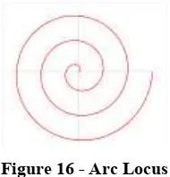
Figure 15 - Segment Locus (a “parallel” and a “splaying” locus with respect to a given geodesic line.)
Figure 16 - Arc Locus
9.
Airspace aggregation
9.1. Background
There are two main ways to describe the geometry of airspace volumes in the AI Domain:
▪ by providing a horizontal border and vertical limits;
▪ by providing a composition rule by which the airspace is defined as a series of unions, intersections, subtractions of other Airspace, such as in the following examples:
o Airspace of type CTR defined as a “circle of 50 NM from which the portion of
airspace situated in a neighboring FIR is subtracted”;
o Airspace of type UIR that has “the same horizontal projection as an FIR”, but
different vertical limits;
o Airspace of type CTA which is the result of aggregating some Airspace of type
SECTOR;
o etc.
The AirspaceVolume class of the AIXM 5 model was designed in order to support the encoding of such aggregated Airspace. Note that the “operation” property of the AirspaceGeometryComponent is used. This makes this encoding not-directly understandable for a standard GML tool and requires software customisation.
Although GML supports the creation of composite surfaces using “patches”, it is not possible to leave this aggregation to the GML level because the vertical limits of the different components might be different. The possibility of using 3D geometries might be considered in future. Until then, using only 2D GML components requires custom processing of AIXM/GML files in order to correctly represent the result of an airspace aggregation, in particular the use of the operation and operationSequence attributes of the AirspaceGeometryComponent class.
9.2. GML encoding
The model gives the possibility for using several approaches for the encoding of airspace aggregations/dependencies. The use of a particular method, from the ones described further in this section, depends on the intended use of the data.
In order to exemplify these methods, the example of an Airspace of type “CTA” will be used.
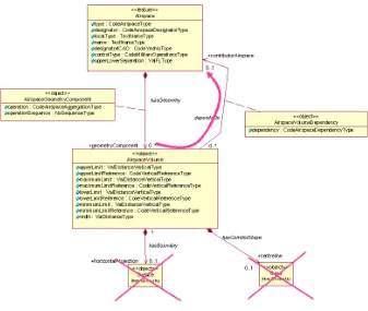
9.2.1. By reference
Figure 17 - Model use for airspace aggregation by reference
This method might be appropriate for data provision between synchronized databases, such as between a local and a regional database and it is equivalent to the approach of the previous AIXM 4.5 version (which is not based on GML). The disadvantage of this method is that the client needs to eventually retrieve the geometry of the referenced Airspace and do the geospatial calculations that are necessary in order to effectively get the actual geometry of the current Airspace in a GML usable form. The advantage is that it preserves a true association with the composing Airspace. An encoding example is provided below:
…
<aixm:type>CTA</aixm:type>
<aixm:designator>EADD</aixm:designator> <aixm:name>CTA DONLON</aixm:name> <aixm:geometryComponent>
<aixm:AirspaceGeometryComponent gml:id="AV001"> <aixm:operation>BASE</aixm:operation>
<aixm:operationSequence>1</aixm:operationSequence> <aixm:theAirspaceVolume>
<aixm:AirspaceVolume gml:id="V001"> <aixm:contributorAirspace>
<aixm:AirspaceVolumeDependency gml:id="VV001">
<aixm:theAirspace xlink:href="
urn:uuid:204451c5-be5e-4eaf-8859-0a62b24a389d" xlink:title="SECTOR DONLON EAST"/>
</aixm:AirspaceVolumeDependency>
<aixm:AirspaceGeometryComponent gml:id="AV002"> <aixm:operation>UNION</aixm:operation>
<aixm:operationSequence>2</aixm:operationSequence> <aixm:theAirspaceVolume>
<aixm:AirspaceVolume gml:id="V002"> <aixm:contributorAirspace>
<aixm:AirspaceVolumeDependency gml:id="VV002">
<aixm:dependency>FULL_GEOMETRY</aixm:dependency>
<aixm:theAirspace xlink:href="
urn:uuid:b936e0e4-2b58-404f-9d95-d95c421c50d2" xlink:title="SECTOR DONLON WEST"/>
</aixm:AirspaceVolumeDependency>
9.2.1.1. Temporal aspects for abstract references
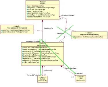
9.2.2. By copying the geometry
The second method consists in effectively copying the geometry of the referenced Airspace as local AirspaceVolume. Note that this might be a recursive operation, as the referenced Airspace might have more than one AirspaceVolume and some or even all these could also depend on the geometry of other Airspace.
Figure 18 - Model use for airspace aggregations when copying referenced geometries
This method might be appropriate for applications that need to provide fully digested geometrical data for direct consumption (e.g. graphical visualization, spatial calculations). The disadvantage of this method is that the referenced geometry might also change in time. This is not a problem when the aggregation is used for the provision of SNAPSHOT data (valid at a time instant) but it might become problematic when providing Baseline data (which is valid for a period of time). Future changes of the geometry of referenced airspace needs to be propagated to the AirspaceVolume of the aggregated airspace. The advantage is that this method provides complete geometrical data for the aggregated Airspace and does not require further calculations by the client system. An encoding example is provided below:
<aixm:type>CTA</aixm:type>
<aixm:designator>EADD</aixm:designator> <aixm:name>CTA DONLON</aixm:name> <aixm:geometryComponent>
<aixm:AirspaceGeometryComponent gml:id="AV001"> <aixm:operation>BASE</aixm:operation>
<aixm:operationSequence>1</aixm:operationSequence> <aixm:theAirspaceVolume>
<aixm:AirspaceVolume gml:id="V001">
<aixm:upperLimit uom="FL">245</aixm:upperLimit>
<aixm:upperLimitReference>STD</aixm:upperLimitReference> <aixm:lowerLimit uom="FL">30</aixm:lowerLimit>
<aixm:lowerLimitReference>STD</aixm:lowerLimitReference> <aixm:horizontalProjection>
<aixm:Surface gml:id="S001"> <gml:patches>
<gml:PolygonPatch> <gml:exterior>
<gml:Ring>
<gml:curveMember>
<aixm:Curve gml:id="C001"> <gml:segments>
<gml:GeodesicString>
<gml:posList>52.18556 5.20833 52.20611
5.2875 52.18917 5.29889 52.16917 5.29889 52.18556 5.20833</gml:posList>
</gml:GeodesicString>
<aixm:AirspaceGeometryComponent gml:id="AV002"> <aixm:operation>UNION</aixm:operation>
<aixm:operationSequence>2</aixm:operationSequence> <aixm:theAirspaceVolume>
<aixm:AirspaceVolume gml:id="V002">
<aixm:upperLimit uom="FL">245</aixm:upperLimit>
<aixm:upperLimitReference>STD</aixm:upperLimitReference> <aixm:lowerLimit uom="FL">50</aixm:lowerLimit>
<aixm:lowerLimitReference>STD</aixm:lowerLimitReference> <aixm:horizontalProjection>
<gml:curveMember>
<aixm:Curve gml:id="C002"> <gml:segments>
<gml:GeodesicString>
<gml:posList>52.20611 5.2875 52.18917
5.29889 52.19117 5.3289 52.20611 5.2875</gml:posList>
</gml:GeodesicString> </gml:segments>
</aixm:Curve> </gml:curveMember> </gml:Ring>
</gml:exterior> </gml:PolygonPatch> </gml:patches>
</aixm:Surface> </aixm:horizontalProjection> </aixm:AirspaceVolume> </aixm:theAirspaceVolume> </aixm:AirspaceGeometryComponent> </aixm:geometryComponent>
</aixm:AirspaceTimeSlice> …
9.2.3. Combined method
10.
Point references and annotations
10.1. Background
Positions of Navaids or Designated Points may be used in the AI Domain in order to define the shape of an Airspace. They can be used as arc centers or even as boundary points. In the case of NOTAM messages, the latitude/longitude coordinates may be followed by geographical references, such as in the example below.
“E) AIR DISPLAY WILL TAKE PLACE WI LATERAL LIMITS: 443838N 0200818E (NDB OBR) - 444508N 0201455E (VILLAGE JAKOVO) - 443445N 0202447E - 443838N 0200818E (NDB OBR). F) GND G) 3000FT AMSL)”
This is not always a reference to a significant point, it can be simply an annotation of a position (e.g. “Village Jakovo”). However, the encoding solution being quite similar, this case also is discussed here.
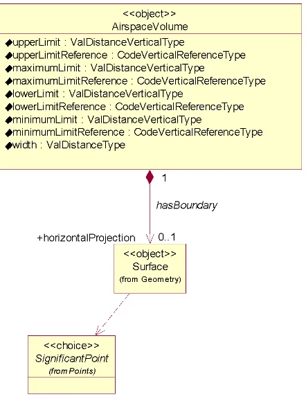
The UML model of AIXM shows a “dependency” association between Surface and SignificantPoint in order to cater for such situations:
Figure 19 - Point references model in AIXM
“dependency” also indicates that the actual encoding can be done differently, based on the intended use of the data.
10.2. GML encoding
The encoding of point references and annotations can be done using gml:pointProperty elements, which can appear as a descendant of gml:Curve, for example in the construction of a gml:GeodesicString. Note that the pointProperty allows either referring to another gml:Point (by xlink:href) or providing a gml:Point child element.
According to the GML standard, para 10.2.2.2: “A property that has a point as its value domain may either be an appropriate geometry element encapsulated in an element of this type or an XLink reference to a remote geometry element (where remote includes geometry elements located elsewhere in the same document). Either the reference or the contained element shall be given, but neither both nor none.”
10.2.1. Using aixm:Point annotations
In this case, a gml:pointProperty is used, including an aixm:Point with an annotation (aixm:Note). This encoding has the advantage that the geometry is self-contained (the position of the referenced object is directly copied as a gml:pos element).
This method should be used whenever the data is intended “for human consumption”, such as in the case of the NOTAM examples (e.g. “VILLAGE JAKOVO”). Even in the case when an arc center is located on a DME navaid and the distance information provided by the DME can be used to keep the aircraft inside or outside the arc, the provision of a Point annotation could be sufficient for the end user.
An example is provided below: …
<gml:exterior> <gml:Ring>
<gml:curveMember>
<gml:Curve gml:id="C001"> <gml:segments>
<gml:GeodesicString>
<gml:posList>52.1855 5.2083 52.2061 5.2875 52.1891 5.2988 52.1691 5.2988</gml:posList> </gml:GeodesicString>
<!-- The next segment contains a point annotation encoded as a Note-->
<gml:GeodesicString>
<gml:pos>52.16917 5.29889</gml:pos> <gml:pointProperty>
<aixm:Point gml:id="P001">
<gml:pos>52.16917 5.21972</gml:pos> <aixm:annotation>
<aixm:Note gml:id="N001"> <aixm:translatedNote>
<aixm:LinguisticNote gml:id="N002">
<aixm:note lang="ENG">VILLAGE JAKOVO</aixm:note> </aixm:LinguisticNote>
</aixm:annotation> </aixm:Point>
</gml:pointProperty> </gml:GeodesicString>
<!-- This is the final straight segment encoded as a Geodesic, which closes the surface--> <gml:GeodesicString>
<gml:posList>52.16917 5.21972 52.18556 5.20833</gml:posList> </gml:GeodesicString>
When necessary to preserve as a true reference the information that the current position depends on the location of another aeronautical feature, then a gml:PointProperty with a xlink:href attribute can be used. In this case, there shall be no child gml:Point/gml:pos element. The GML standard requires a local reference, using a gml:id value.
10.2.2.1. Local reference to gml:Point (or equivalent)
In the example below, the position of the Navaid is used as centre for the circle that defines the horizontal geometry of the Airspace.
<aixm:Navaid gml:id="urn.uuid.791fb712-6c7a-46bb-8e98-49d76942573e"> …
<aixm:type>VOR_DME</aixm:type> <aixm:name>DONLON</aixm:name> <aixm:location>
<aixm:ElevatedPoint gml:id="P0001" srsName="urn:ogc:def:crs:EPSG::4326"> <gml:pos>52.2889 -32.0350</gml:pos>
<aixm:elevation uom="FT">365</aixm:elevation> </aixm:ElevatedPoint>
</aixm:location> …
</aixm:Navaid> …
<aixm:Airspace gml:id="urn.uuid. fc5b4fb3-004e-42c4-8552-6566d25a09f7">
…
<aixm:theAirspaceVolume>
<aixm:AirspaceVolume gml:id="V001"> <aixm:horizontalProjection>
<aixm:Surface gml:id="S001" srsName="urn:ogc:def:crs:EPSG::4326"> <gml:polygonPatches>
<gml:PolygonPatch> <gml:exterior> <gml:Ring>
<gml:curveMember>
xlink:title="VOR/DME DONLON"/> <gml:radius uom="[nmi_i]">12</gml:radius> </gml:CircleByCenterPoint>
This solution is appropriate when the data is provided for direct consumption by a GML tool for display or other calculation purpose. Obviously, it requires that both the Airspace and the referenced feature (Navaid, DesignatedPoint, etc.) are included in the same file. It might be problematic to apply this solution in the case of WFS getFeature requests, because the referenced feature will not be present in the response.
Note also that the xlink:title attribute is used to provide a human readable identification of the Navaid that is referred, which can be used in printed documents.
This solution does not imply the persistence of the gml:id value. It is still a temporary identifier, which enables linking the gml:PointProperty with the gml:Point or one of its allowed substitutions (aixm:Point, aixm:ElevatedPoint) inside the file.
This direct link between gml:PointProperty and gml:Point is a deviation from the general AIXM principle of having xlink:href associations towards the feature level only. However, this direct association with the gml:Point property of the aixm:Navaid is the only solution identified for really encoding geometry dependencies at the GML level. In a source database, the association can still be towards the Navaid itself (as detailed in the next section). Only for data export/import purpose the reference would be towards the gml:Point directly.
10.2.3. Summary
In conclusion, there are two options for encoding point references in AIXM/GML: ▪ as a simple annotation
▪ as a local concrete xlink:href reference using gml:id
11.
Geographical border references
11.1. Background
In the AI Domain, Airspace boundaries may be based on national borders or on other geographical features, such as shorelines, rivers, etc.
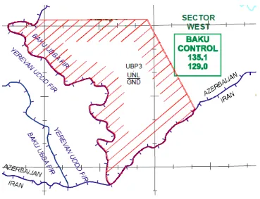
An example of such an Airspace border is provided below:
“UBP3
400300N 0455323E - 400300N 0465600E - 392545N 0472148E -
then along the state border with Islamic Republic of Iran up to 385222N 0463250E - then along the state border with Armenia up to 400300N - 0455323E”
Figure 20 - Airspace UBP3 borders
The UML model of AIXM shows a “dependency” association between Surface and GeoBorder in order to cater for such situations:
Figure 21 - GeoBorder references model in AIXM
Similarly to Significant Point references (as discussed in 7.1), the reason for using a “dependency” association and not a standard “object to feature association” is that this occurs deep inside the GML encoding of the Surface. Using a “dependency” also indicates that the actual encoding can be done differently, based on the intended use of the data.
11.2. GML encoding
The encoding of GeoBorder references can be done in two ways:
▪ either using the “annotation” property of an aixm:Curve, for applications where a simple text remark is sufficient;
▪ or using the xlink:href attribute of a gml:curveMember, for applications where a true reference needs to be preserved.
11.2.1. Using aixm:Curve annotations
This method should be used when the information (that this part of the airspace border actually comes from a GeoBorder) is intended “for human consumption”, such as for directly displaying the Airspace on a screen or printing on paper. An example is provided below:
<aixm:Airspace gml:id="urn.uuid.1965dd58-6898-4065-8f21-b1774c959bbb"> …
<aixm:horizontalProjection>
<aixm:Surface gml:id="S001" srsName="urn:ogc:def:crs:EPSG::4326"> <gml:polygonPatches>
<gml:PolygonPatch> <gml:exterior>
<gml:Ring>
<gml:curveMember>
<gml:Curve gml:id="CUR001"> <gml:segments>
<gml:LineStringSegment interpolation="linear">
<!-- because the two consecutive points have the same latitude, the first segment is encoded as a parallel (linear interpolation in EPSG:4326) -->
<gml:posList> 40.05 45.88972222 40.05
46.93333333</gml:posList>
</gml:LineStringSegment>
<gml:GeodesicString interpolation="geodesic"> <gml:posList>40.05 46.93333333 39.42916667
47.36333334</gml:posList>
</gml:GeodesicString>
</gml:segments>
</gml:Curve>
</gml:curveMember>
<!-- Here starts the first portion of the Airspace border that was extracted (copied) from a GeoBorder. In this case, the reference to the GeoBorder is a simple text annotation.-->
<gml:curveMember>
<aixm:Curve gml:id="CUR002"> <gml:segments>
<gml:GeodesicString interpolation="geodesic">
<gml:posList>39.42916667 47.36333334 39.426818 47.353277 39.405269 47.340623 39.370714 47.303951 39.317977 47.213494 39.304679 47.147725 39.253854 47.075486 39.209945 47.064339 39.138967 46.950699 39.160036 46.929733 39.135505 46.835985 39.113835 46.826968 39.110637 46.818902 39.104488 46.811639 39.084995 46.792338 39.079520 46.774177 39.063644 46.761250 39.035348 46.762985 39.015666 46.733063 39.019323 46.695507 38.991019 46.690236 38.987819 46.672322 38.930984 46.626817 38.906155 46.600158
38.885792 46.560942 38.885160 46.554943 38.87277778 46.54722222</gml:posList>
</gml:GeodesicString>
</gml:segments>
<aixm:annotation>
<aixm:Note gml:id="N001"> <aixm:translatedNote>
<aixm:LinguisticNote gml:id="N002">
<aixm:note lang="ENG">along the state border with
Islamic Republic of Iran</aixm:note>
</aixm:LinguisticNote>
</aixm:translatedNote>
</gml:curveMember> …
</aixm:Airspace>
Note that the first point of the curveMember that contains the portion extracted from the GeoBorder (39.42916667 47.36333334) is equal with the last point of the previous curveMember. This satisfies the requirement stated in the GML Standard (ISO 19136, 10.5.11.1 - Ring, RingType, curveMember) that “In the context of a ring, the curves describe the boundary of the surface. The sequence of curves shall be contiguous and connected in a cycle.” In order to match this requirement when encoding existing Airspace data an additional gml:curveMember might be necessary. This is required in order to connect the last specified point of the Airspace boundary before the GeoBorder with the first vertex of the GeoBorder. It is typically a very short segment which does not alter the geometry. However, its presence is important in order to have a contiguous Surface border.
11.2.2. Using xlink:href
When necessary to preserve as a true reference the (that a part of the airspace border actually comes from a GeoBorder), then a gml:curveMember with a xlink:href attribute can be used. In this case, there shall be no child aixm:Curve or gml:Curve element. The GML standard requires a local reference, using a gml:id value. For compatibility reasons with previous AIXM versions and to satisfy the operational needs of the AI domain, it is also allowed to use a remote reference. The two solutions are detailed here.
11.2.2.1. Local reference to aixm:Curve
In this example, the gml:curveMember contains a local reference (xlink:href) to the gml:id value of an aixm:Curve that contains the relevant geo border points. The referred aixm:Curve is embedded into an ad-hoc GeoBorder SNAPSHOT TimeSlice. This GeoBorder TimeSlice is “ad-hoc4” because it contains just the sub-set of point that need to be embedded.
<aixm:Airspace gml:id="urn.uuid.1965dd58-6898-4065-8f21-b1774c959bbb">
…
<aixm:horizontalProjection>
<aixm:Surface gml:id="S001" srsName="urn:ogc:def:crs:EPSG::4326"> <gml:polygonPatches>
<gml:PolygonPatch> <gml:exterior>
<gml:Ring>
<gml:curveMember>
<gml:Curve gml:id="CUR001"> <gml:segments>
<gml:LineStringSegment interpolation="linear">
<!-- because the two consecutive points have the same latitude, the first segment is encoded as a parallel (linear interpolation in EPSG:4326) -->
4