DESIGN OF DRY CASK STORAGE FOR SERPONG MULTI
PURPOSE REACTOR SPENT NUCLEAR FUEL
Dyah Sulistyani Rahayu, Yuli Purwanto, Zainus Salimin Center for Radioactive Waste Technology
Puspiptek Area, Serpong,Tangerang Selatan, Banten 15314 e-mail: [email protected]
(Naskah diterima: 14–12–2017, Naskah direvisi: 28–01–2018, Naskah disetujui: 01–02–2018)
ABSTRACT
DESIGN OF DRY CASK STORAGE FOR SERPONG MULTI PURPOSE REACTOR SPENT NUCLEAR FUEL. The spent nuclear fuel (SNF) from Serpong Multipurpose Reactor, after 100 days storing in the reactor pond, is transferred to water pool interim storage for spent fuel (ISFSF). At present there are a remaining of 245 elements of SNF on the ISSF,198 element of which have been re-exported to the USA. The dry-cask storage allows the SNF, which has already been cooled in the ISSF, to lower its radiation exposure and heat decayat a very low level. Design of the dry cask storage for SNF has been done. Dual purpose of unventilated vertical dry cask was selected among other choices of metal cask, horizontal concrete modules, and modular vaults by taking into account of technical and economical advantages. The designed structure of cask consists of SNF rack canister, inner steel liner, concrete shielding of cask, and outer steel liner. To avoid bimetallic corrosion, the construction material for canister and inner steel liner follows the same material construction of fuel cladding, i.e. the alloy of AlMg2. The construction material of outer steel liner is copper to facilitate the heat transfer from the cask to the atmosphere. The total decay heat is transferred from SNF elements bundle to the atmosphere by a serial of heat transfer resistance for canister wall, inner steel liner, concrete shielding, and outer steel liner respectedly. The rack canister optimum capacity of 34 fuel elements was designed by geometric similarity method basedon SNF position arrangement of 7 x 6 triangular pitch array of fuel elements for prohibiting criticality by spontaneous neutron. The SNF elements are stored vertically on the rack canister. The thickness of concrete wall shielding was calculated by trial and error to give air temperature of 30 oC and radiation dose on the wall surface of outer
liner of 200 mrem/h. The SNF elements bundles originate from the existing racks of wet storage, i.e. rack canister no 3, 8 and 10. The value of I0 from the rack no 3, 8 and 10 are 434.307;
446.344; and 442.375 mrem/h respectively. The total heat decay from rack canister no 3,8 and 10 are 179.640 ; 335.2; and 298.551 watts. The result of the trial and error calculation indicates that the rack canister no 3, 8 and 10 need the thickness of concrete shielding of 0.1912, 0.1954 and 0.1940 m respectively.
ABSTRAK
PERANCANGAN WADAH PENYIMPANAN KERING BAHAN BAKAR NUKLIR BEKAS REAKTOR SERBA GUNA SERPONG. Bahan Bakar Nuklir Bekas (BBNB) dari Reaktor Serba Guna Serpong setelah 100 hari disimpan di kolam reaktor, kemudian dipindahkan ke instalasi penyimpanan sementara bahan bakar bekas nuklir bekas (IPSB3). Pada saat ini ada 245 elemen BBNB yang tersisa dan 198 elemen telah diekspor kembali ke Amerika Serikat. Wadah penyimpanan kering dari BBNB yang telah didinginkan di IPSB3 mengalami peluruhan radiasi dan panas sangat rendah yaitu maksimum 18,2989 watt per elemen. Desain wadah penyimpanan kering untuk BBNB telah dilakukan dan pemilihan wadah logam, modul beton horisontal, dan kubah modular karena keunggulan teknis dan ekonomisnya. Struktur wadah yang dirancang terdiri dari tabung rak BBNB, liner baja dalam, perisai beton dan liner baja luar. Upaya menghindari korosi bimetalik, bahan konstruksi untuk kanister dan lapisan baja mengikuti material yang sama dengan material kelongsong bahan bakar yaitu AlMg2. Material liner baja luar terbuat dari tembaga untuk memudahkan perpindahan panas dari wadah ke atmosfer. Panas peluruhan total ditransfer dari elemen BBNB ke atmosfer oleh resistansi perpindahan panas serial dari dinding tabung, lapisan baja dalam, perisai beton, dan lapisan baja luar masing-masing. Kapasitas rak yang optimum dari kanister adalah 34 elemen bahan bakar dirancang dengan metode kemiripan geometrik basis susunan posisi BBNB 7 x 6 untuk menghambat kekritisan neutron secara spontan. Elemen BBNB disimpan secara vertikal pada tabung rak kanister. Ketebalan perisai dinding beton dihitung dengan trial and error sehingga memberikan temperatur udara 30 oC dan dosis radiasi pada permukaan dinding liner luar sebesar 200 mrem/jam. Elemen
BBNB berasal dari rak penyimpanan basah yaitu rak no. 3, 8 dan 10. Nilai peluruhan (I0) dari rak
no 3, 8 dan 10 masing-masing adalah 434,307; 446,344; dan 442,375 mrem/jam. Peluruhan panas total dari rak 3,8 dan 10 adalah 179,640; 335.2; dan 298,551 watt. Hasil trial and error menunjukkan bahwa untuk rak no 3, 8 dan 10 membutuhkan ketebalan beton perisai masing-masing sebesar 0,1912, 0,19954 dan 0,1940 m.
INTRODUCTION enrichment depends upon the specific reactor design. The SNF contains the radionuclides of the remaining uranium, trans-uranium, fission product, and activations product.
Activation products are
materials made radioactive by neutron
activation. The SNF generates the heat and
radiation decay of its radionuclides. The primary objective of the SNF handling is that it must be stored in a safe, economical, and environmentally acceptable manner until it is transferred to a repository for final disposal. This may be accomplished in storage facilities at the reactor, in facilities located away from reactor, or by a combinations storage at reactor and transport to the disposal facilities away from reactor.[3]. The SNF assemblies are moved into the water pools existing at all reactor buildings from the reactor vessel along water canals. The SNF remains cooling in the pool and waits about three years for another interim storage that can be dry storage, or for a final disposal [4]. On the unloading period from the Multipurpose Research Reactor of GA.Siwabessy (MPR-GAS), the element of SNF has the heat and radiation decay about 47,590 watts and 145 µSv/h respectively. At first, the SNF was stored temporarily during 100 days for cooling to reduce heat from 47,590 to 377.2 W per SNF element. The SNF is then transferred to water pool interim storage for spent fuel (ISFSF), using wet transfer channel (TC) containing water shielding. The TC is also utilized for transferring the irradiation target from the MPR-GAS to the Radioisotope Production Facility andthe SNF from the Radiometalurgi Facility to the ISFSF [5,6]. Since the operations of the MPR-GAS on the year of 1987, until 443 elements of SNF had beenunloaded to the ISFSF in which the 198 elements having uranium origin from Unites States of America (USA) was reexported to USA.
This activity is based on
the repatriations agreement between Indonesia and USA government. At the present there are remaining of 245 elements of SNF on the ISFSF, among them the oldest and youngest decay periodes are 21 and 4 years respectively. The ISFSF has the maximum storage capacity of 1448 elements of SNF. The heat generated at that capacity is 35 kW and the heat from lighting system and the others is 5 kW. Water cooling system on the ISFSF was designed for removing the heat by circulations of the 6 m3/h water pool tothe cooling system for maintaining of constants water pool temperature of 35 oC.
The ISFSF has also the ventilations and air conditioning system for maintaining of constant air temperature at 20-25 oC and
relative humidity of 40-60 %, room negative pressure of 100-25 Pa and radiations exposure of 2-5 mrem/h by air renewal of 5 times per hour [6,7]. For the 245 elements of SNF generates the total heat decay about 6 kW, for maintaining the temperature of the ISFSF pool water about 35 oC, it is required
management of the SNF conforming the regulations aspect. Determining of the cask type, optimum number of the SNF element on cask for avoiding the criticality, safe container thickness, safe shielding thickness and the constructions of the cask.
a) Storage of The Spent Nuclear Fuel Spent nuclear fuel that is generated in the operation of nuclear reactors needs to be safely managed following its removal from the reactor core. Reactor storage pools were designed on the assumption that after a short period of time spent nuclear fuel would be romoval for reprocessing, disposal or storage elsewhere [8]. The principal consideratios can summarized as follows : 1) Release Limits
The release of radionuclides into environment during the course of normal handling (in the air borne or liquid form) must be maintained below the limits established by the regulatory authorities. 2) Accident Conditions
The facility must be designed to minimixed the possibility of the following types of event during the operation preferred method. This is particularly true in case of irradiated fuel from power reactor which must be ready to receive fuel freshly discharged from reactor because of the high thermal output of these assemblies.
In any method of spent fuel storage, the basic functions of the facilities required here are [3,4]:
a) Removal of heat from the fuel, which means to the carry away heat produced by radioactive decay of fissions products and transuranium elements.
b) Radiation shielding, i.e to maintain acceptably low levels of radiation in working areas.
c) Containment of radioactive materials that is to prevent the potential release of radionuclides into working area and general environment. Heat removal is accomplished by use of cooling medium, such as water or air. Shielding against radiations is obtained by storing the fuel well below water in an appropriate depth or by containing the fuel in cavity surrounded by solid material, such as concrete or earth sufficiently thick to prevent levels of radiations from penetrating it. Containment is accomplished by storing the fuel under water, in a vault, or in container which prevents the release of significant quantities of radioactive materials even during accident conditions.
Although the generation of both heat and radioactivity is continuous, the amount of heat produced and the amount of radionuclides contained decreases with time as the decay of fission products proceeds. The Table 1 and Figure 1 indicates the decay heat of the SNF of MPR-GAS (MTR300 gU 235, 72% burn up) as function of unloading time from the reactor [1,5]. The decay heat per element of SNF as the function of time is indicated on the following equation 1 [6] :
q = 78.0369.t -1.062 (1)
in which q is the heat decay (watt/element) and t is the time (year). The decay radiations per element of SNF as the functions time is shown on the following equation 2 [6]:
R.D = 144.55 t-0.048 (2)
Table 1. Decay heat of the SNF element of MPR-GAS as the function of time[7]
Decay time Decay heat (watt/element)
0 day 4.75 E4 spent fuel storage in vaults, silos and casks.
Vaults consist of above or below ground reinforced concrete buildings containing arrays of storage cavities suitable for containment of one or more fuel units. Shielding is provided by the exterior structure. Heat removal is normally accomplished by forced or natural convection of air or gas over the exterior of the fuel containing units or storage cavities, and subsequently exhausting this air directly to the outside atmosphere or dissipating the heat via a secondary heat removal system.
Silo or concrete canister is a massive container comprising one or more individual storage cavities. It is usually circular in cross-section, with its long vertical axis. Isolation and shielding are provided by an inner, sealed liner and the massive concrete of the canister body. Heat removal is accomplished by radiant transfer, conduction and convection within the body of the canister and natural convection at its exterior surface.
Cask is a massive container that may be used for transport, storage and eventual disposal of the spent fuel. It provides shielding and containment of spent fuel by physical barriers which may include provides structural resistance, subcriticality and closing through a double cover. The casks can have single, dual or multiple-purposes. The spent fuel transport option by cask is called a single-purpose and the transport and storage options are called dual-purpose. The multi-purpose term is reserved for the casks that are designed with the transport, storage and disposal options. The IPEN studies are concentrated only in dual-purpose casks [9].
In general, metal casks, horizontal concrete modules and modular vaults have been the primary methods used to store the SNF. Recently, vertical concrete casks have received consideration for storage of the SNF. The practical fields indicates that the vertical concrete dry storage casks are economically and technically competitive with metal cask, horizontal concrete modules, and modular vaults. According the metode of its air cooling, there are two type of dry storage casks i.e ventilated and unventilated casks. United State Departement Energy (DOE) developed a retrievable ventilated dry storage casks. The casks was utilized for storing the SNF or vitrified high level waste. Natural convection caused air to enter inlets at the bottom of the cask, flow upward through an annulus temperature of the concrete cask wall[10].
The decay heat from spent fuel bundles of baskets be transferred to the serial heat resistance on the squence of wall of basket, inner steel layer, concrete shielding and outer steel liner by conduction heat transfer, then finally from outer liner to the atmospheric air by convections and radiation heat transfers. The outer steel liner is selected from the steel having the biggest conductivity to make easy the heat tranfer to the air. The unventillated dry storage cask is utilized to store only older of the SNF. The decay radiation penetrates the serial of radiation resistance on the wall sequence of canister, inner steel liner, concrete shielding, and outer steel line.
Figure 1. Overview of MACSTOR [11]
The advantages of the dry storage are: storage in inert atmosphere, no corrosion problems of the fuel, natural cooling possible, no running equipment, no maintenance, contamination of the environment unlikely, the fuel package can be transported, safeguards is easy [12].
c) Heat Transfer on The Dry Storage Cask Wall
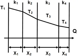
The total heat of spent fuel bundles will be transferred by conduction heat transfer to the serial heat transfer of the wall sequence i.e canister, inner steel layer, concrete shielding, and outer steel liner as shown schematically in Figure 2 and 3. According the conduction heat transfer following the formula of that heat transfer follows as the equation of [13,14,15,16]:
𝑄 = 𝑇1− 𝑇4/ ∑ 𝑅 (3)
In which : T1, T2, T3 and T4 are the
temparature of the wall of canister, inner steel liner, concrete shielding, and outer steel liner, and
∑
𝑅 is the serial heat transfer resistance.Figure 2. The side viewing of result design of the canister
Figure 3. The top viewing result design of the canister
Conforming the Figure 4, the serial heat transfer resistance (
∑
𝑅) follows the following equation [13,14,15,16]:Figure 4. The squence of serial heat transfer resistance on the dry cask
∑ 𝑅 =
𝑋1𝑘1.𝐴1
+
𝑋2
𝑘2.𝐴2
+
𝑋3
𝑘3.𝐴3
+
𝑋4
𝑘4.𝐴4
(4)
are 0.0215; 0.0330; and 0.0330 m recpectivelly [17].
When the heat of Q has already penetrated the four serial heat transfer resitance, the temperature of outer steel liner will be becomes on the value of T4. The
heat of Q is then transferred from the outer steel liner to the atmospheric air by conventions and radiation heat transfer. The heat transfer by convection follows the equation [13,14,15]
𝑞1= ℎ. 𝐴 (𝑇4− 𝑇5 ) (5)
In which h is the heat transfer coefficient of natural convection to air, A is the heat transfer surface area, T4 and T5 are
temperature of outer steal linier and atmospheric air respectively. The value of h is under influence of the form of surface and the kind of flow (streamlines/laminer or turbulent) as shown on the Table 2.
Table 2. The value of heat transfer coefficient of natural convection to air [11].
Form of Surface Streamlines Turbulent
Horizontal or vertical pipe h = 1.18 (ΔT/do)1/4 h = 1.65 (ΔT)1/4
Vertical planes h = 1.35 (ΔT/I)1/4 h = 2.00 (ΔT)1/4
Horizontal planes facing upward h = 1.31 (ΔT/do)1/4 h = 2.33 (ΔT)1/4
Horizontal planes facing downward h = 0.59 (ΔT/do)1/4
Notes :
q = heat transfer (W/h)
I = thicknes of the air thin layer on the planes surface
do = thicknes of the air thin layer on the pipe surface
ΔT = difference temperature for surface and air (K)
h = natural convection heat transfer (W/m2.K)
The heat transfer by radition follows the equation [13,14,15] :
𝑞2= 𝜖𝜎𝐴
(
𝑇44− 𝑇54)
(6)Q= 𝑞1+𝑞2
Q=ℎ. 𝐴 (𝑇4− 𝑇5 )+𝜖𝜎𝐴(𝑇44− 𝑇54) (7)
In which :
= emissivity of material surface (W/m2K)
σ = Stefan- Boltzman Constant = 5.67. 10-8 (W/m2K)
A = Surface area of material (m2) T4 = temperature of material surface (K)
T5 = temperature of atmospheric air
d) Radiation Shielding on The Dry Cask Storage
The radiation shielding is utilized to maintain acceptable low levels of radiation in
working area or environmenal area. The spent fuel bundles on the canister emits the radiation on the total dose rate of I0. The
radiation dose of I0 penetrates the serial of
radiation resistance of squence wall of canister, inner steel liner, concrete shelding, and outer steel liner. The dose rate of I0 after
penetrating that four of serial wall will be decrease to dose rate of I4 as indicated in
the Figure 5 by the decreasing squence of I1,
I2, I3, and I4 as shown on the following
equation [17,18]:
𝐼1= 𝐼0. 𝑒−𝜇1𝑥1 (8)
𝐼2= 𝐼1. 𝑒−𝜇2𝑥2 (9)
𝐼3= 𝐼2. 𝑒−𝜇3𝑥3 (10)
𝐼4= 𝐼3. 𝑒−𝜇4𝑥4 (11)
𝐼4= 𝐼0. 𝑒−(𝜇1𝑥1+𝜇2𝑥2+𝜇3𝑥3+𝜇4𝑥4) (12)
In which : I0 is the radiation dose from the
SNF bundles, I1 I2, I3 and I4 are the radiation
dose of the squence wall of canister, inner steel liner, concrete shelding and outer steel liner respectively. µ1, µ2, µ3, and µ4 are the
Figure 5. The squence of serial radiation penetration resitance on the dry cask
e) Standard Rack for the SNF of MPR-GAS
The SNF of MPR-GAS at the present is stored on the ISFSF of waterpool type in the rack positioned at the bottom of pool. The rack was designed on the parameter condition for preventing the criticality of the SNF by its spontaneous neutron. The rack has the square cross-section form and the dimension of 0.94 m x 0.94 m x 1.10 m containing 6 x 7 grid or 42 of the SNF per rack with the SNF distance of 140 mm as indicated on the Figure 6.
Figure 6. Geometric similarity following the existing rack for design of the canister
For designing the canister, the geometric similarity concept is utilized in which the following valid equation is applicable for another cross-section form.
𝐴1
𝑁1
=
𝐴2
𝑁2
= − − −− =
𝐴
𝑁
(
13)In which :A1 and A are the cross
section area of the existing rack having the SNF capacity of 42 element and the designed rack respectively, N1 and N2 are
the SNF capacity on the existing rack (42) and the designed rack respectively.
METHODOLOGY a) Materials
The canister and inner liner materials are used in the same material as the SNF cladding is AlMg2. This material is selected for canister, and inner liner there will be no bimetallic corrosion. As for the outer liner material selected copper material to facilitate the heat transfer from SNF through the walls of the canister, inner steel liner wall, wall shielding, toward the atmosphere. This is to avoid the accumulation of heat. Heat in the cask flow smoothly so that selected materials must have a high thermal conductivity
b) Work Procedures for Design of Dry Cask Storage
The procedures for design of dry cask srtorage consist of several calculation sequence of the following steps :
1) Selections of type and shape of dry cask storage
2) Calculation of canister capacity based on the geometry similarity concept of the SNF existing rack 3) Calculation of the total heat and
radiation of decay generating from the SNF bundles on the designed canister.
4) Selection of construction materials of canister, inner steel liner, concrete shielding, and outer steel liner.
5) Selection the standard thicknes of the canister, inner steel and outer steel liner.
and temperature on the wall of outer
The selected dry storage cask is the Unventilated Vertical Concrete Storage cask as shown in the Figure 1. It is feasible and could become and important alternative methode for the SNF storage, transport, and possible storage. The concrete is a good material than glass, polymer and bitumen for a transport cask and only minor refinements in the design and fabrication method are
required. The SNF bundles on the canister having the cylindrical cross-section are putted on the midle of casks. For avoiding the criticaly of spent fuels the structure of selected canister is designed by the geometris similarity concept of the existing standard rack as shown in the Figure 6.
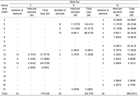
The result of canister design is on the Figure 2 and 3, the canister has the SNF elements capacity of 34 with the its configuration of 3, 5, 6, 6, 6, 5, 3. The diameter of designed cylindrical canister are 0.94. By utilization the data of decay heat of the SNF element as the fuction of time, the total heat of 34 SNF element on the rack number of 3, 8, and 10 can be calculated as shown in the Table 3
Table 3. Total of heat decay for 34 of the SNF elements from the existing racks no 3,8 and 10.
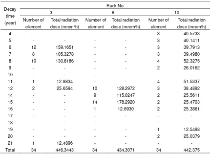
Table 4. Table dose of radiation decay for 34 of the SNF elements from the existing rack.
Decay time (year)
Rack No
3 8 10
Number of element
Total radiation dose (mrem/h)
Number of element
Total radiation dose (mrem/h)
Number of element
Total radiation dose (mrem/h)
4 - - - - 3 40.5733
5 - - - - 3 40.1411
6 12 159.1651 - - 3 39.7913
7 8 105.3278 - - 3 39.4980
8 10 130.8186 - - 4 52.3275
9 - - - - 2 26.0162
10 - - - -
11 1 12.8834 - - 4 51.5337
12 2 25.6594 10 128.2972 3 38.4892
14 - - 9 115.0247 2 25.5611
15 - - 14 178.2920 2 25.4703
16 - - 1 12.6930 2 25.3861
17 - - - -
18 - - - -
19 - - - - 1 12.5498
20 - - - - 2 25.0379
21 1 12.4896 - - - -
Total 34 446.3443 34 434.3071 34 442.375
The construction material of the SNF of MPR-GAS is the steel alloy of AlMg2
in which there are 98% of Al and 2% of Mg. For avoiding the galvanic corrosion of contacted two different metal, the alloy of AlMg2 is utilized also for construction
materials of canister and inner steel liner. For facilitating the heat transfer from outer steel liner to the atmospheric air, the material construction of copper is utilized for outer steel liner. According to the United
State Nuclear Waste Technical Review Board, the applicable thickness of canister, inner steel, and outer steel liner are 0.0215; 0.0330; and 0.0330 m respectively. The selected of construction materials for canister, inner steel liner, shielding, and outer steel liner are AlMg2,heavy concrete and copper respectively. Calculation result of the outer steel liner (X4) thickness for dry
cask of rack number of 3, 8 and 10 as shown in Table 5
Table 5. Resulting calculation of the thickness of outer steel liner (X4) for dry cask.
Number of rack
Radiation dose
(mrem/h) Absorbtion coefficient (cm
-1)
Thickness of construction material (cm)
Resulting calculation
of X4 (cm)
I0 I µ1 µ2 µ3 µ4 X1 X2 X3
The value of µ1, µ2, µ3, and µ4 are
0.0718; 0,.0718; 0.0646; and 0.0207 cm-1.
The standard value of x1, x2, and x4 are
0.0215; 0.0330; and 0.0330 m. The value of I0 after the radiation penetration the four
construction materials of dry cask will be became I4 in which the safe its value is
200 mrem/h. By utilization of equation 12 in which the value of I0, µ1, µ2, µ3, µ4, X1, X2, X3
and I are known, the value of the thicknes of concrete shielding (X4) can be calculated.
utilization of the equation of 3 and 4 with the assumption that the safe value of T4 is
40 oC. The k1, k2, k3, and k4 are the thermal
conductivity of material construction for canister, inner steel liner, concrete shielding and outer steel liner respectively. The value of k1, k2, k3 and k4 are 216; 216; 1.5 and
377 W/mK [11]. The A1, A2, A3 and A4 are
heat transfer surface area (as the outer blanket surface of cylinder) of canister, inner steel liner, concrete shielding, and outer
result of dry cask storage number 1, 2 and 3 conforming the rack no 3, 8 and 10 are 46.8091; and 52.8280; and 51.4061 oC
respectively. That resulting temperature are still on the safe value of temperature conforming the allowable maximum temparature on the surface of the SNF i.e
vertical of steel material (0.78 W/m2K). from
the equation of the value of T5 (temperature
of atmospheric air ) can be calculated. The
Design of canister for unventilated vertical concrete dry cask storage by geometric similarity conforming the existing rack. That design for avoiding the criticality results the canister with thickness of 0.0215 and diameter of 0.94 m. Design capacity is 34 of SNF elements with its configuration of 3, 5, 6, 6, 6, 5, 3 holes.The design result in
unventilated vertical concrete dry cask storage is selected for dual purpose utilization i.e transportation and storage.
ACKNOWLEDGMENT
We thank to our colleagues from Center for Radiactive Waste Management whose services turned my research a success.
REFERENCES
[2] Z. Salimin and A. Soeripto, “Spent Fuel Management Strategy for Future Nuclear Power Plant Operation in Indonesia,” Proceeding of International Conference on Storage of Spent Fuel from Power Reactor, June 2003, Vienna, Austria.
[3] International Atomic Energy Agency, “Storage of Spent Nuclear Fuel,” Specific Safety Guide No. SSG-15, Vienna, Austria, 2012.
[4] R. L. Sergio, “Advantages of Hardened Cask Storage Over Wet Storage For Spent Nuclear Fuel,” International Nuclear Atlantic Conference-INAC 2011, Brazil. [5] Z. Salimin, “Heat Transfer Analysis on
the Storage of Spent Fuel of Indonesian Multi Purpose Reactor 30 MW,” Proceeding of 6th International
Topical Meeting on Nuclear Reactor Thermal Hydraulic Operation, October 2004, Nara, Japan.
[6] Z. Salimin, “Aspect of Operation Safety for the Facility of Transfer Channel on Interim Storage for Spent Fuel,” Final Technical Report of Insentive Program, 2012.
[7] BATAN-IAEA, “Engineering Contract Transfer Channel and ISFSF for BATAN,” Atomic Energy Agency of United Kingdom , 1992.
[8] Hoi, Dry Cask Storage, Standford University, March, 2014.
[9] A. T. Silva, M. M. Neto, R.P. Mourao, L. L. Silva, C. C. Lopes, and M. C. C. Silva, “Options for the interim storage of IEA-R1 research reactor spent fuels,” Progress in Nuclear Energy, An International Review Journal, vol.50, pp.836–844, 2008.
[10] W. L. Hurt, “Material Interaction on Canister Integrity During Storage and Transport. Management and Storage of Research Reactor Spent Nuclear Fuel,” Proceeding of A Technical Meeting, 2013, IAEA, Vienna.
[11] M. Tayal and M. Gacesa, “Storage and Disposal of Irradiated Fuel,” Darlington Environmental Assesement, Chapter 19, Nuclear Waste Management, December 2015. [12] J. Kastelein, “Reactor Spent Nuclear Fuel: National Practice for Interim Storage in The Netherlands Central Organisation for Storage of Radioactive Waste (COVRA6 N.V),” Proceeding Series Management and Storage of Research Reactor Spent Nuclear Fuel, October 2009, United Kingdom.
[13] J. M. Coulson and J. F. Richardson, Chemical Enginering Volume 2, 4th
Edition, Pergamon Press, Oxford, 1991.
[14] D. Q. Kern, Process Heat Transfer, International Edition, Mc.Graw-Hill Book. Co, New York, 1965.
[15] W. L. Badger and J. T. Banchero, Introduction to Chemical Engineering, McGraw-Hill Book Co, New York, 1988.
[16] W. L. Mac Cabe, J. C. Smith, and P. Harriot, Unit Operation of Chemical Engineering, Fourth Edition, McGraw-Hill Book Co, New York, 1985.
[17] United State Nuclear Waste Technical
Review Board, Dry Cask
Spesification, 2010.
![Table 1. Decay heat of the SNF element of MPR-GAS as the function of time[7]](https://thumb-ap.123doks.com/thumbv2/123dok/1662608.2073155/5.595.93.288.129.262/table-decay-heat-snf-element-mpr-gas-function.webp)
![Table 2. The value of heat transfer coefficient of natural convection to air [11].](https://thumb-ap.123doks.com/thumbv2/123dok/1662608.2073155/7.595.137.475.277.351/table-value-heat-transfer-coefficient-natural-convection-air.webp)