Front Mat t er Table of Cont ent s I ndex
About t he Aut hor
Un ifie d M ode lin g La n gu a ge Use r Gu ide , Th e
Grady BoochJames Rumbaugh Ivar Jacobson
Publisher: Addison Wesley First Edition October 20, 1998 ISBN: 0-201-57168-4, 512 pages
In The Unified Modeling Language User Guide, the original
developers of the UML--Grady Booch, James Rumbaugh, and Ivar Jacobson--provide a tutorial to the core aspects of the language in a two-color format designed to facilitate learning. Starting with a conceptual model of the UML, the book progressively applies the UML to a series of increasingly complex modeling problems across a variety of application domains. This example-driven approach helps readers quickly understand and apply the UML. For more advanced developers, the book includes a learning track focused on applying the UML to advanced modeling problems.
With The Unified Modeling Language User Guide, readers will: Understand what the UML is, what it is not, and why it is relevant to the development of software-intensive systems
Master the vocabulary, rules, and idioms of the UML in order to "speak" the language effectively
Learn how to apply the UML to a number of common modeling problems
See illustrations of the UML©s use interspersed with use cases for specific UML features, and
Gain insight into the UML from the original creators of the UML.
Un ifie d M ode lin g La n gu a ge Use r Gu ide , Th e
Many of the designations used by manufacturers and sellers to
distinguish their products are claimed as trademarks. Where those
designations appear in this book, and Addision Wesley Longman
Inc. was aware of a trademark claim, the designations have been
printed in initial caps are all in caps.
The publisher offers discounts on this book when ordered in
quantity for special sales. For more information, please contact:
AWL Direct Sales
Addison Wesley Longman, Inc.
One Jacob Way
Reading, Massachusetts 01867
(781) 944-3700
Visit AW on the Web: ht t p: / / w w w .aw l.com / cseng/
Library of Congress Cataloging-in-Publication Data
Booch, Grady.
The unified modeling language user guide / Grady Booch, James
Rumbaugh, and Ivar Jacobson.
p. cm. -- (Addison-Wesley object technology series)
Includes index.
ISBN 0-201-57168-4
1. Computer software--Development. 2. UML (Computer science) I.
Rumbaugh, James. II. Jacobson, Ivar. III. Title. IV. Series.
QA76.76.D47B655 1998.
005.1'7--dc21 98-30436
CIP
Copyright
–
1999 by Addison-Wesley Longman Inc.
All rights reserved. No part of this publication may be reproduced,
stored in a retrieval system, or transmitted, in any form or by any
means, electronic, mechanical, photocopying, recording, or
otherwise, without the prior written permission of the publisher.
Printed in the United States of America. Published simultaneously
in Canada.
Photo Credits: The illustrations on pages 1, 203, and 341 are from
A Visual Dictionary of Architecture,
Francis Ching,
–
1997 by Van
Nostrand Reinhold. Adapted by permission of John Wiley & Sons,
Inc. The illustrations on pages 45, 117, 275, and 429 are from
Ching,
–
1996 by Van Nostrand Reinhold. Adapted by permission
of John Wiley & Sons, Inc.
Text printed on recycled and acid-free paper.
6 7 8 9 1011 MA 03 02 01 00
6th printing, April 2000
Credits
Executive Editor:
J. Carter Shanklin
Editorial Assistant:
Meg Tangirala
Copy Editor:
Arlene Richman
Cover Designer:
Simone R. Payment
Project Editor:
Krysia Bebick
Production Manager:
Sarah Weaver
Compositor:
Grady Booch
To my loving wife, Jan, and my goddaughter, Elyse, both of whom
make me whole.
Grady Booch
Un ifie d M ode lin g La n gu a ge Use r Gu ide , Th e
Preface Goals Audience
How t o Use This Book
Organizat ion and Special Feat ures A Brief Hist ory of t he UML
I : Get t ing St art ed I : Get t ing St art ed
1. Why We Model
The I m port ance of Modeling Principles of Modeling Obj ect - Orient ed Modeling 2. I nt roducing t he UML An Overview of t he UML
A Concept ual Model of t he UML Archit ect ure
Soft w are Developm ent Life Cycle
3. Hello, World! Key Abst ract ions Mechanism s Com ponent s
I I : Basic St ruct ural Modeling I I : Basic St ruct ural Modeling
4. Classes Get t ing St art ed Term s and Concept s
Com m on Modeling Techniques Hint s and Tips
5. Relat ionships Get t ing St art ed Term s and Concept s
Com m on Modeling Techniques Hint s and Tips
6. Com m on Mechanism s Get t ing St art ed
Term s and Concept s
Com m on Modeling Techniques Hint s and Tips
7. Diagram s Get t ing St art ed Term s and Concept s
Com m on Modeling Techniques Hint s and Tips
8. Class Diagram s Get t ing St art ed Term s and Concept s
I I I : Advanced St ruct ural Modeling I I I : Advanced St ruct ural Modeling
9. Advanced Classes Get t ing St art ed Term s and Concept s
Com m on Modeling Techniques Hint s and Tips
10. Advanced Relat ionships Get t ing St art ed
Term s and Concept s
Com m on Modeling Techniques Hint s and Tips
11. I nt erfaces, Types, and Roles Get t ing St art ed
Term s and Concept s
Com m on Modeling Techniques Hint s and Tips
12. Packages Get t ing St art ed Term s and Concept s
Com m on Modeling Techniques Hint s and Tips
13. I nst ances Get t ing St art ed Term s and Concept s
Com m on Modeling Techniques Hint s and Tips
14. Obj ect Diagram s Get t ing St art ed Term s and Concept s
Com m on Modeling Techniques Hint s and Tips
I V: Basic Behavioral Modeling I V: Basic Behavioral Modeling
15. I nt eract ions Get t ing St art ed Term s and Concept s
Com m on Modeling Techniques Hint s and Tips
16. Use Cases Get t ing St art ed Term s and Concept s
17. Use Case Diagram s Get t ing St art ed
Term s and Concept s
Com m on Modeling Techniques Hint s and Tips
18. I nt eract ion Diagram s Get t ing St art ed
Term s and Concept s
Com m on Modeling Techniques Hint s and Tips
19. Act ivit y Diagram s Get t ing St art ed Term s and Concept s
Com m on Modeling Techniques Hint s and Tips
V: Advanced Behavioral Modeling V: Advanced Behavioral Modeling
20. Event s and Signals Get t ing St art ed Term s and Concept s
Com m on Modeling Techniques Hint s and Tips
21. St at e Machines Get t ing St art ed Term s and Concept s
Com m on Modeling Techniques Hint s and Tips
22. Processes and Threads Get t ing St art ed
Term s and Concept s
Com m on Modeling Techniques Hint s and Tips
23. Tim e and Space Get t ing St art ed Term s and Concept s
Com m on Modeling Techniques Hint s and Tips
24. St at echart Diagram s Get t ing St art ed
Term s and Concept s
Com m on Modeling Technique Hint s and Tips
VI : Archit ect ural Modeling
25. Com ponent s Get t ing St art ed Term s and Concept s
Com m on Modeling Techniques Hint s and Tips
26. Deploym ent Get t ing St art ed Term s and Concept s
Com m on Modeling Techniques Hint s and Tips
27. Collaborat ions Get t ing St art ed Term s and Concept s
Com m on Modeling Techniques Hint s and Tips
28. Pat t erns and Fram ew orks Get t ing St art ed
Term s and Concept s
Com m on Modeling Techniques Hint s and Tips
29. Com ponent Diagram s Get t ing St art ed
Term s and Concept s
Com m on Modeling Techniques Hint s and Tips
30. Deploym ent Diagram s Get t ing St art ed
Term s and Concept s
Com m on Modeling Techniques Hint s and Tips
31. Syst em s and Models Get t ing St art ed
Term s and Concept s
Com m on Modeling Techniques Hint s and Tips
VI I : Wrapping Up VI I : Wrapping Up
32. Applying t he UML Transit ioning t o t he U ML Where t o Go Next
Relat ionships Ext ensibilit y Diagram s
B. UML St andard Elem ent s St ereot ypes
Tagged Values Const raint s
C. Rat ional Unified Process Charact erist ics of t he Process Phases and I t erat ions
Glossary Glossary
Preface
The Unified Modeling Language (UML) is a graphical language for visualizing, specifying,
constructing, and documenting the artifacts of a software-intensive system. The UML gives you a standard way to write a system's blueprints, covering conceptual things, such as business processes and system functions, as well as concrete things, such as classes written in a specific programming language, database schemas, and reusable software components.
This book teaches you how to use the UML effectively.
Goals
In this book, you will
• Learn what the UML is, what it is not, and why the UML is relevant to the process of developing software-intensive systems
• Master the vocabulary, rules, and idioms of the UML and, in general, learn how to "speak" the language effectively
• Understand how to apply the UML to solve a number of common modeling problems
The user guide provides a reference to the use of specific UML features. However, it is not intended to be a comprehensive reference manual for the UML; that is the focus of another book,
The Unified Modeling Language Reference Manua l (Rumbaugh, Jacobson, Booch, Addison-Wesley, 1999).
The user guide describes a development process for use with the UML. However, it is not intended to provide a complete reference to that process; that is the focus of yet another book,
The Unified Software Development Process (Jacobson, Booch, Rumbaugh, Addison-Wesley, 1999).
Finally, this book provides hints and tips for using the UML to solve a number of common modeling problems, but it does not teach you how to model. This is similar to a user guide for a programming language that teaches you how to use the language but does not teach you how to program.
The UML is applicable to anyone involved in the production, deployment, and maintenance of software. The user guide is primarily directed to members of the development team who create UML models. However, it is also suitable to those who read them, working together to
understand, build, test, and release a software-intensive system. Although this encompasses almost every role in a software development organization, the user guide is especially relevant to analysts and end users (who specify the required structure and behavior of a system), architects (who design systems that satisfy those requirements), developers (who turn those architectures into executable code), quality assurance personnel (who verify and validate the system's structure and behavior), librarians (who create and catalogue components), and project and program managers (who generally wrestle with chaos, provide leadership and direction, and orchestrate the resources necessary to deliver a successful system).
The user guide assumes a basic knowledge of oriented concepts. Experience in an object-oriented programming language or method is helpful but not required.
How to Use This Book
For the developer approaching the UML for the first time, the user guide is best read linearly. You should pay particular attention to Chapt er 2, which presents a conceptual model of the UML. All chapters are structured so that each builds upon the content of the previous one, thus lending itself to a linear progression.
For the experienced developer seeking answers to common modeling problems using the UML, this book can be read in any order. You should pay particular attention to the common modeling problems presented in each chapter.
Organization and Special Features
The user guide is organized into seven major sections:
• Sect ion 1 Get t ing St art ed
• Sect ion 2 Basic St ruct ural Modeling
• Sect ion 3 Advanced St ruct ural Modeling
• Sect ion 4 Basic Behavioral Modeling
• Sect ion 5 Advanced Behavioral Modeling
• Sect ion 6 Archit ect ural Modeling
• Sect ion 7 Wrapping Up
The user guide contains three appendices: a summary of the UML notation, a list of standard UML elements, and a summary of the Rational Unified Process. A glossary of common terms is also provided.
Each chapter addresses the use of a specific UML feature, and most are organized into the following four sections:
1. Getting Started 2. Terms and Concepts
4. Hints and Tips
The third section introduces and then solves a set of common modeling problems. To make it easy for you to browse the guide in search of these use cases for the UML, each problem is identified by a distinct heading, as in the following example.
Modeling Architectural Patterns
Each chapter begins with a summary of the features it covers, as in the following example.
In this chapter
•
Active objects, processes, and threads
•
Modeling multiple flows of control
•
Modeling interprocess communication
•
Building thread-safe abstractions
Similarly, parenthetical comments and general guidance are set apart as notes, as in the following example.
Note
You can specify more complex multiplicities by using a list, such as 0..1, 3..4, 6..*, which would mean "any number of objects other than 2 or 5."
Components are discussed in Chapt er 25.
The UML is semantically rich. Therefore, a presentation about one feature may naturally involve another. In such cases, cross references are provided in the left margin, as on this page.
Blue highlights are used in figures to distinguish text that explains a model from text that is part of the model itself. Code is distinguished by displaying it in a monospace font, as in this
example.
A Brief History of the UML
high-level design, and OMT-2 was most useful for analysis and data-intensive information systems. The behavioral component of many object-oriented methods, including the Booch method and OMT, was the language of statecharts, invented by David Harel. Prior to this object-oriented adoption, statecharts were used mainly in the realm of functional decomposition and structured analysis, and led to the development of executable models and tools that generated full running code.
A critical mass of ideas started to form by the mid 1990s, when Grady Booch (Rational Software Corporation), Ivar Jacobson (Objectory), and James Rumbaugh (General Electric) began to adopt ideas from each other's methods, which collectively were becoming recognized as the leading object-oriented methods worldwide. As the primary authors of the Booch, OOSE, and OMT methods, we were motivated to create a unified modeling language for three reasons. First, our methods were already evolving toward each other independently. It made sense to continue that evolution together rather than apart, eliminating the potential for any unnecessary and gratuitous differences that would further confuse users. Second, by unifying our methods, we could bring some stability to the object-oriented marketplace, allowing projects to settle on one mature modeling language and letting tool builders focus on delivering more useful features. Third, we expected that our collaboration would yield improvements for all three earlier methods, helping us to capture lessons learned and to address problems that none of our methods previously handled well.
As we began our unification, we established three goals for our work:
1. To model systems, from concept to executable artifact, using object- oriented techniques 2. To address the issues of scale inherent in complex, mission-critical systems
3. To create a modeling language usable by both humans and machines
Devising a language for use in object-oriented analysis and design is not unlike designing a programming language. First, we had to constrain the problem: Should the language encompass requirements specification? Should the language be sufficient to permit visual programming? Second, we had to strike a balance between expressiveness and simplicity. Too simple a
language would limit the breadth of problems that could be solved; too complex a language would overwhelm the mortal developer. In the case of unifying existing methods, we also had to be sensitive to the installed base. Make too many changes, and we would confuse existing users; resist advancing the language, and we would miss the opportunity of engaging a much broader set of users and of making the language simpler. The UML definition strives to make the best trade-offs in each of these areas.
The UML effort started officially in October 1994, when Rumbaugh joined Booch at Rational. Our project's initial focus was the unification of the Booch and OMT methods. The version 0.8 draft of the Unified Method (as it was then called) was released in October 1995. Around the same time, Jacobson joined Rational and the scope of the UML project was expanded to incorporate OOSE. Our efforts resulted in the release of the UML version 0.9 documents in June 1996. Throughout 1996, we invited and received feedback from the general software engineering community. During this time, it also became clear that many software organizations saw the UML as strategic to their business. We established a UML consortium, with several organizations willing to
Between January 1997 and July 1997, the original group of partners was expanded to include virtually all of the other submitters and contributors of the original OMG response, including Andersen Consulting, Ericsson, ObjecTime Limited, Platinum Technology, PTech, Reich Technologies, Softeam, Sterling Software, and Taskon. A semantics task force was formed, led by Cris Kobryn of MCI Systemhouse and administered by Ed Eykholt of Rational, to formalize the UML specification and to integrate the UML with other standardization efforts. A revised version of the UML (version 1.1) was offered to the OMG for standardization in July 1997. In September 1997, this version was accepted by the OMG Analysis and Design Task Force (ADTF) and the OMG Architecture Board and then put up for vote by the entire OMG membership. UML 1.1 was adopted by the OMG on November 14, 1997.
Maintenance of the UML was then taken over by the OMG Revision Task Force (RTF), led by Cris Kobryn. The RTF released an editorial revision, UML 1.2, in June 1998. In fall 1998, the RTF released UML 1.3, which this user guide describes, providing some technical cleanup.
Acknowledgments
Grady Booch, Ivar Jacobson, and James Rumbaugh began the UML effort and throughout the project were its original designers, but the final product was a team effort among all the UML partners. Although all partners came with their own perspectives, areas of concern, and areas of interest, the overall result has benefited from the contributions of each of them and from the diversity of their experience and viewpoints.
The core UML team included
• Hewlett-Packard: Martin Griss
• I-Logix: Eran Gery, David Harel
• IBM: Steve Cook, Jos Warmer
• ICON Computing: Desmond D'Souza
• Intellicorp and James Martin and Company: James Odell
• MCI Systemhouse: Cris Kobryn, Joaquin Miller
• ObjecTime: John Hogg, Bran Selic
• Oracle: Guus Ramackers
• Platinum Technology: Dilhar DeSilva
• Rational Software: Grady Booch, Ed Eykholt, Ivar Jacobson, Gunnar Overgaard, Karin Palmkvist, James Rumbaugh
• Taskon: Trygve Reenskaugh
• Texas Instruments/Sterling Software: John Cheesman, Keith Short
• Unisys: Sridhar Iyengar, G.K. Khalsa
Cris Kobryn deserves a special acknowledgment for his leadership in directing the UML technical team during the development of UML 1.1, 1.2, and 1.3.
nonetheless appreciated for their influence: Jim Amsden, Hernan Astudillo, Colin Atkinson, Dave Bernstein, Philip Bernstein, Michael Blaha, Conrad Bock, Mike Bradley, Ray Buhr, Gary
Cernosek, James Cerrato, Michael Jesse Chonoles, Magnus Christerson, Dai Clegg, Geoff Clemm, Peter Coad, Derek Coleman, Ward Cunningham, Raj Datta, Philippe Desfray, Mike Devlin, Bruce Douglass, Staffan Ehnebom, Maria Ericsson, Johannes Ernst, Don Firesmith, Martin Fowler, Adam Frankl, Eric Gamma, Dipayan Gangopadhyay, Garth Gullekson, Rick Hargrove, Tim Harrison, Richard Helm, Brian Hendersen-Sellers, Michael Hirsch, Bob Hodges, Yves Holvoet, Jon Hopkins, John Hsia, Glenn Hughes, Ralph Johnson, Anneke Kleppe, Philippe Kruchten, Paul Kyzivat, Martin Lang, Grant Larsen, Reed Letsinger, Mary Loomis, Jeff MacKay, Joe Marasco, Robert Martin, Terri McDaniel, Jim McGee, Mike Meier, Randy Messer, Bertrand Meyer, Greg Meyers, Fred Mol, Luis Montero, Paul Moskowitz, Andy Moss, Jan Pachl, Paul Patrick, Woody Pidcock, Bill Premerlani, Jeff Price, Jerri Pries, Terry Quatrani, Mats Rahm, Rudolf Riess, Rich Reitman, Erick Rivas, Kenny Rubin, Jim Rye, Danny Sabbahr, Tom Schultz, Colin Scott, Ed Seidewitz, Keith Short, Gregson Sui, Jeff Sutherland, Dan Tasker, Andy Trice, Dave Tropeano, Dan Uhlar, John Vlissides, Larry Wall, Paul Ward, Alan Willis, Rebecca Wirfs-Brock, Bryan Wood, Ed Yourdon, and Steve Zeigler.
The development of the UML was an open process, and via the OTUG (Object Technology User's Group) we received thousands of e-mail messages from all over the world. Although we cannot mention every submitter by name, we do thank all of them for their comments and suggestions. We really did read each message, and the UML is better because of this broad international feedback.
A special acknowledgment also goes to a small band of lab rats (Loud and Boisterous RATional Students) who participated in a user guide course led by Booch in early 1997, during which they offered excellent ideas and gave much constructive criticism that helped fine-tune the contents of this book: Hernan Astudillo, Robin Brown, Robert Bundy, Magnus Christerson, Adam Frankl, Nookiah Kolluru, Ron Krubek, Grant Larsen, Dean Leffingwell, Robert Martin, Mills Ripley, Hugo Sanchez, Geri Schneider, Tom Schultz, Andy Trice, Dan Uhlar, and Lloyd Williams. Thanks go to the madmen at Number Six Software and to the folks who provided a technical review of this book: Jack Carter, Tim Budd, Bruce Douglass, Martin Fowler, Cris Kobryn, Philippe Kruchten, Ron Lusk, Terry Quatrani, and David Rine.
For More Information
The most current information about the UML, including its formal specification, may be found on the Internet at ht t p: / / w w w .r at ional.com and ht t p: / / w w w .om g.org. The work of the revision task force may be found at uml.shl.com.
There are several electronic forums that are appropriate for general discussion about the UML, including the Internet news groups comp.software-eng and comp.object and the public mailing lists ot ug@rat ional.com and um l- rt f@om g.org.
Grady Booch Lakewood, Colorado September 1998 egb@rat ional.com
Chapter 1. Why We Model
In this chapter
• The importance of modeling
• Four principles of modeling
• The essential blueprints of a software system
• Object-oriented modeling
A successful software organization is one that consistently deploys quality software that meets the needs of its users. An organization that can develop such software in a timely and predictable fashion, with an efficient and effective use of resources, both human and material, is one that has a sustainable business.
source code. Rather, it is good software that satisfies the evolving needs of its users and the business. Everything else is secondary.
Unfortunately, many software organizations confuse "secondary" with "irrelevant." To deploy software that satisfies its intended purpose, you have to meet and engage users in a disciplined fashion, to expose the real requirements of your system. To develop software of lasting quality, you have to craft a solid architectural foundation that's resilient to change. To develop software rapidly, efficiently, and effectively, with a minimum of software scrap and rework, you have to have the right people, the right tools, and the right focus. To do all this consistently and predictably, with an appreciation for the lifetime costs of the system, you must have a sound development process that can adapt to the changing needs of your business and technology. Modeling is a central part of all the activities that lead up to the deployment of good software. We build models to communicate the desired structure and behavior of our system. We build models to visualize and control the system's architecture. We build models to better understand the system we are building, often exposing opportunities for simplification and reuse. We build models to manage risk.
The Importance of Modeling
If you want to build a dog house, you can pretty much start with a pile of lumber, some nails, and a few basic tools, such as a hammer, saw, and tape measure. In a few hours, with little prior planning, you'll likely end up with a dog house that's reasonably functional, and you can probably do it with no one else's help. As long as it's big enough and doesn't leak too much, your dog will be happy. If it doesn't work out, you can always start over, or get a less demanding dog.
If you want to build a house for your family, you can start with a pile of lumber, some nails, and a few basic tools, but it's going to take you a lot longer, and your family will certainly be more demanding than the dog. In this case, unless you've already done it a few dozen times before, you'll be better served by doing some detailed planning before you pound the first nail or lay the foundation. At the very least, you'll want to make some sketches of how you want the house to look. If you want to build a quality house that meets the needs of your family and of local building codes, you'll need to draw some blueprints as well, so that you can think through the intended use of the rooms and the practical details of lighting, heating, and plumbing. Given these plans, you can start to make reasonable estimates of the amount of time and materials this job will require. Although it is humanly possible to build a house yourself, you'll find it is much more efficient to work with others, possibly subcontracting out many key work products or buying pre-built materials. As long as you stay true to your plans and stay within the limitations of time and money, your family will most likely be satisfied. If it doesn't work out, you can't exactly get a new family, so it is best to set expectations early and manage change carefully.
If you want to build a high-rise office building, it would be infinitely stupid for you to start with a pile of lumber, some nails, and a few basic tools. Because you are probably using other people's money, they will demand to have input into the size, shape, and style of the building. Often, they will change their minds, even after you've started building. You will want to do extensive planning, because the cost of failure is high. You will be just a part of a much larger group responsible for developing and deploying the building, and so the team will need all sorts of blueprints and models to communicate with one another. As long as you get the right people and the right tools and actively manage the process of transforming an architectural concept into reality, you will likely end up with a building that will satisfy its tenants. If you want to keep building buildings, then you will want to be certain to balance the desires of your tenants with the realities of building technology, and you will want to treat the rest of your team professionally, never placing them at any risk or driving them so hard that they burn out.
Sometimes, you get lucky. If you have the right people at the right moment and if all the planets align properly, then you might, just might, get your team to push out a software product that dazzles its users. Typically, however, you can't get all the right people (the right ones are often already overcommitted), it's never the right moment (yesterday would have been better), and the planets never seem to align (instead, they keep moving out of your control). Given the increasing demand to develop software in Internet time, development teams often fall back on the only thing they really know how to do well•pound out lines of code. Heroic programming efforts are legend
in this industry, and it often seems that working harder is the proper reaction to any crisis in development. However, these are not necessarily the right lines of code, and some projects are of such a magnitude that even adding more hours to the work day is not enough to get the job done.
If you really want to build the software equivalent of a house or a high rise, the problem is more than just a matter of writing lots of software•in fact, the trick is in creating the right software and
in figuring out how to write less software. This makes quality software development an issue of architecture and process and tools. Even so, many projects start out looking like dog houses but grow to the magnitude of a high rise simply because they are a victim of their own success. There comes a time when, if there was no consideration given to architecture, process, or tools, that the dog house, now grown into a high rise, collapses of its own weight. The collapse of a dog house may annoy your dog; the failure of a high rise will materially affect its tenants.
Unsuccessful software projects fail in their own unique ways, but all successful projects are alike in many ways. There are many elements that contribute to a successful software organization; one common thread is the use of modeling.
Modeling is a proven and well-accepted engineering technique. We build architectural models of houses and high rises to help their users visualize the final product. We may even build
mathematical models in order to analyze the effects of winds or earthquakes on our buildings. Modeling is not just a part of the building industry. It would be inconceivable to deploy a new aircraft or an automobile without first building models•from computer models to physical wind
tunnel models to full-scale prototypes. New electrical devices, from microprocessors to telephone switching systems require some degree of modeling in order to better understand the system and to communicate those ideas to others. In the motion picture industry, storyboarding, which is a form of modeling, is central to any production. In the fields of sociology, economics, and business management, we build models so that we can validate our theories or try out new ones with minimal risk and cost.
What, then, is a model? Simply put,
A model is a simplification of reality.
A model provides the blueprints of a system. Models may encompass detailed plans, as well as more general plans that give a 30,000-foot view of the system under consideration. A good model includes those elements that have broad effect and omits those minor elements that are not relevant to the given level of abstraction. Every system may be described from different aspects using different models, and each model is therefore a semantically closed abstraction of the system. A model may be structural, emphasizing the organization of the system, or it may be behavioral, emphasizing the dynamics of the system.
Why do we model? There is one fundamental reason.
We build models so that we can better understand the system we are developing.
How the UML addresses these four things is discussed in Chapt er 2. 1. Models help us to visualize a system as it is or as we want it to be. 2. Models permit us to specify the structure or behavior of a system. 3. Models give us a template that guides us in constructing a system. 4. Models document the decisions we have made.
Modeling is not just for big systems. Even the software equivalent of a dog house can benefit from some modeling. However, it's definitely true that the larger and more complex the system, the more important modeling becomes, for one very simple reason:
We build models of complex systems because we cannot comprehend such a system in its entirety.
There are limits to the human ability to understand complexity. Through modeling, we narrow the problem we are studying by focusing on only one aspect at a time. This is essentially the
approach of "divide-and-conquer" that Edsger Dijkstra spoke of years ago: Attack a hard problem by dividing it into a series of smaller problems that you can solve. Furthermore, through modeling, we amplify the human intellect. A model properly chosen can enable the modeler to work at higher levels of abstraction.
Saying that one ought to model does not necessarily make it so. In fact, a number of studies suggest that most software organizations do little if any formal modeling. Plot the use of modeling against the complexity of a project, and you'll find that the simpler the project, the less likely it is that formal modeling will be used.
The operative word here is "formal." In reality, in even the simplest project, developers do some amount of modeling, albeit very informally. A developer might sketch out an idea on a blackboard or a scrap of paper in order to visualize a part of a system, or the team might use CRC cards to work through a scenario or the design of a mechanism. There's nothing wrong with any of these models. If it works, by all means use it. However, these informal models are often ad hoc and do not provide a common language that can easily be shared with others. Just as there exists a common language of blueprints for the construction industry, a common language for electrical engineering, and a common language for mathematical modeling, so too can a development organization benefit by using a common language for software modeling.
Every project can benefit from some modeling. Even in the realm of disposable software, where it's sometimes more effective to throw away inadequate software because of the productivity offered by visual programming languages, modeling can help the development team better visualize the plan of their system and allow them to develop more rapidly by helping them build the right thing. The more complex your project, the more likely it is that you will fail or that you will build the wrong thing if you do no modeling at all. All interesting and useful systems have a natural tendency to become more complex over time. So, although you might think you don't need to model today, as your system evolves you will regret that decision, after it is too late.
Principles of Modeling
The use of modeling has a rich history in all the engineering disciplines. That experience suggests four basic principles of modeling. First,
In other words, choose your models well. The right models will brilliantly illuminate the most wicked development problems, offering insight that you simply could not gain otherwise; the wrong models will mislead you, causing you to focus on irrelevant issues.
Setting aside software for a moment, suppose you are trying to tackle a problem in quantum physics. Certain problems, such as the interaction of photons in time-space, are full of
wonderfully hairy mathematics. Choose a different model than the calculus, and all of a sudden this inherent complexity becomes tractable. In this field, this is precisely the value of Feynmann diagrams, which provide a graphical rendering of a very complex problem. Similarly, in a totally different domain, suppose you are constructing a new building and you are concerned about how it might behave in high winds. If you build a physical model and then subject it to wind tunnel tests, you might learn some interesting things, although materials in the small don't flex exactly as they do in the large. Hence, if you build a mathematical model and then subject it to simulations, you will learn some different things, and you will also probably be able to play with more new scenarios than if you were using a physical model. By rigorously and continuously testing your models, you'll end up with a far higher level of confidence that the system you have modeled will, in fact, behave as you expect it to in the real world.
In software, the models you choose can greatly affect your world view. If you build a system through the eyes of a database developer, you will likely focus on entity-relationship models that push behavior into triggers and stored procedures. If you build a system through the eyes of a structured analyst, you will likely end up with models that are algorithmic-centric, with data flowing from process to process. If you build a system through the eyes of an object-oriented developer, you'll end up with a system whose architecture is centered around a sea of classes and the patterns of interaction that direct how those classes work together. Any of these approaches might be right for a given application and development culture, although experience suggests that the object-oriented view is superior in crafting resilient architectures, even for systems that might have a large database or computational element. That fact notwithstanding, the point is that each world view leads to a different kind of system, with different costs and benefits.
Second,
Every model may be expressed at different levels of precision.
If you are building a high rise, sometimes you need a 30,000-foot view•for instance, to help your
investors visualize its look and feel. Other times, you need to get down to the level of the studs•
for instance, when there's a tricky pipe run or an unusual structural element.
The same is true with software models. Sometimes, a quick and simple executable model of the user interface is exactly what you need; at other times, you have to get down and dirty with the bits, such as when you are specifying cross-system interfaces or wrestling with networking bottlenecks. In any case, the best kinds of models are those that let you choose your degree of detail, depending on who is doing the viewing and why they need to view it. An analyst or an end user will want to focus on issues of what; a developer will want to focus on issues of how. Both of these stakeholders will want to visualize a system at different levels of detail at different times. Third,
The best models are connected to reality.
In software, the Achilles heel of structured analysis techniques is the fact that there is a basic disconnect between its analysis model and the system's design model. Failing to bridge this chasm causes the system as conceived and the system as built to diverge over time. In object-oriented systems, it is possible to connect all the nearly independent views of a system into one semantic whole.
Fourth,
No single model is sufficient. Every nontrivial system is best approached through a small set of nearly independent models.
If you are constructing a building, there is no single set of blueprints that reveal all its details. At the very least, you'll need floor plans, elevations, electrical plans, heating plans, and plumbing plans.
The operative phrase here is "nearly independent." In this context, it means having models that can be built and studied separately but that are still interrelated. As in the case of a building, you can study electrical plans in isolation, but you can also see their mapping to the floor plan and perhaps even their interaction with the routing of pipes in the plumbing plan.
The five views of an architecture are discussed in Chapt er 2.
The same is true of object-oriented software systems. To understand the architecture of such a system, you need several complementary and interlocking views: a use case view (exposing the requirements of the system), a design view (capturing the vocabulary of the problem space and the solution space), a process view (modeling the distribution of the system's processes and threads), an implementation view (addressing the physical realization of the system), and a deployment view (focusing on system engineering issues). Each of these views may have structural, as well as behavioral, aspects. Together, these views represent the blueprints of software.
Depending on the nature of the system, some models may be more important than others. For example, in data-intensive systems, models addressing static design views will dominate. In GUI-intensive systems, static and dynamic use case views are quite important. In hard real time systems, dynamic process views tend to be more important. Finally, in distributed systems, such as one finds in Web-intensive applications, implementation and deployment models are the most important.
Object-Oriented Modeling
Civil engineers build many kinds of models. Most commonly, there are structural models that help people visualize and specify parts of systems and the way those parts relate to one another. Depending on the most important business or engineering concerns, engineers might also build dynamic models• for instance, to help them to study the behavior of a structure in the presence
of an earthquake. Each kind of model is organized differently, and each has its own focus. In software, there are several ways to approach a model. The two most common ways are from an algorithmic perspective and from an object-oriented perspective.
The contemporary view of software development takes an object-oriented perspective. In this approach, the main building block of all software systems is the object or class. Simply put, an object is a thing, generally drawn from the vocabulary of the problem space or the solution space; a class is a description of a set of common objects. Every object has identity (you can name it or otherwise distinguish it from other objects), state (there's generally some data associated with it), and behavior (you can do things to the object, and it can do things to other objects, as well). For example, consider a simple three-tier architecture for a billing system, involving a user interface, middleware, and a database. In the user interface, you will find concrete objects, such as buttons, menus, and dialog boxes. In the database, you will find concrete objects, such as tables representing entities from the problem domain, including customers, products, and orders. In the middle layer, you will find objects such as transactions and business rules, as well as higher-level views of problem entities, such as customers, products, and orders.
The object-oriented approach to software development is decidedly a part of the mainstream simply because it has proven to be of value in building systems in all sorts of problem domains and encompassing all degrees of size and complexity. Furthermore, most contemporary languages, operating systems, and tools are object-oriented in some fashion, giving greater cause to view the world in terms of objects. Object-oriented development provides the conceptual foundation for assembling systems out of components using technology such as Java Beans or COM+.
These questions are discussed in Chapt er 2.
A number of consequences flow from the choice of viewing the world in an object-oriented fashion: What's the structure of a good object-oriented architecture? What artifacts should the project create? Who should create them? How should they be measured?
Visualizing, specifying, constructing, and documenting object-oriented systems is exactly the purpose of the Unified Modeling Language.
Chapter 2. Introducing the UML
In this chapter
• Overview of the UML
• Three steps to understanding the UML
• Software architecture
• The software development process
The Unified Modeling Language (UML) is a standard language for writing software blueprints. The UML may be used to visualize, specify, construct, and document the artifacts of a software-intensive system.
The UML is only a language and so is just one part of a software development method. The UML is process independent, although optimally it should be used in a process that is use case driven, architecture-centric, iterative, and incremental.
An Overview of the UML
The UML is a language for
• Visualizing
• Specifying
• Constructing
• Documenting
the artifacts of a software-intensive system.
The UML Is a Language
A language provides a vocabulary and the rules for combining words in that vocabulary for the purpose of communication. A modeling language is a language whose vocabulary and rules focus on the conceptual and physical representation of a system. A modeling language such as the UML is thus a standard language for software blueprints.
The basic principles of modeling are discussed in Chapt er 1.
Modeling yields an understanding of a system. No one model is ever sufficient. Rather, you often need multiple models that are connected to one another in order to understand anything but the most trivial system. For software- intensive systems, this requires a language that addresses the different views of a system's architecture as it evolves throughout the software development life cycle.
The vocabulary and rules of a language such as the UML tell you how to create and read well-formed models, but they don't tell you what models you should create and when you should create them. That's the role of the software development process. A well-defined process will guide you in deciding what artifacts to produce, what activities and what workers to use to create them and manage them, and how to use those artifacts to measure and control the project as a whole.
The UML Is a Language for Visualizing
For many programmers, the distance between thinking of an implementation and then pounding it out in code is close to zero. You think it, you code it. In fact, some things are best cast directly in code. Text is a wonderfully minimal and direct way to write expressions and algorithms.
information would be lost forever or, at best, only partially recreatable from the implementation, once that developer moved on.
Writing models in the UML addresses the third issue: An explicit model facilitates communication. Some things are best modeled textually; others are best modeled graphically. Indeed, in all interesting systems, there are structures that transcend what can be represented in a programming language. The UML is such a graphical language. This addresses the second problem described earlier.
The complete semantics of the UML are discussed in The Unified Modeling Language Reference Manual.
The UML is more than just a bunch of graphical symbols. Rather, behind each symbol in the UML notation is a well-defined semantics. In this manner, one developer can write a model in the UML, and another developer, or even another tool, can interpret that model unambiguously. This addresses the first issue described earlier.
The UML Is a Language for Specifying
In this context, specifying means building models that are precise, unambiguous, and complete. In particular, the UML addresses the specification of all the important analysis, design, and implementation decisions that must be made in developing and deploying a software-intensive system.
The UML Is a Language for Constructing
The UML is not a visual programming language, but its models can be directly connected to a variety of programming languages. This means that it is possible to map from a model in the UML to a programming language such as Java, C++, or Visual Basic, or even to tables in a relational database or the persistent store of an object-oriented database. Things that are best expressed graphically are done so graphically in the UML, whereas things that are best expressed textually are done so in the programming language.
Modeling the structure of a system is discussed in Sect ions 2 and 3.
This mapping permits forward engineering: The generation of code from a UML model into a programming language. The reverse is also possible: You can reconstruct a model from an implementation back into the UML. Reverse engineering is not magic. Unless you encode that information in the implementation, information is lost when moving forward from models to code. Reverse engineering thus requires tool support with human intervention. Combining these two paths of forward code generation and reverse engineering yields round-trip engineering, meaning the ability to work in either a graphical or a textual view, while tools keep the two views
consistent.
Modeling the behavior of a system is discussed in Sect ions 4 and 5.
In addition to this direct mapping, the UML is sufficiently expressive and unambiguous to permit the direct execution of models, the simulation of systems, and the instrumentation of running systems.
The UML Is a Language for Documenting
A healthy software organization produces all sorts of artifacts in addition to raw executable code. These artifacts include (but are not limited to)
• Architecture
• Design
• Source code
• Project plans
• Tests
• Prototypes
• Releases
Depending on the development culture, some of these artifacts are treated more or less formally than others. Such artifacts are not only the deliverables of a project, they are also critical in controlling, measuring, and communicating about a system during its development and after its deployment.
The UML addresses the documentation of a system's architecture and all of its details. The UML also provides a language for expressing requirements and for tests. Finally, the UML provides a language for modeling the activities of project planning and release management.
Where Can the UML Be Used?
The UML is intended primarily for software-intensive systems. It has been used effectively for such domains as
• Enterprise information systems
• Banking and financial services
• Telecommunications
• Transportation
• Defense/aerospace
• Retail
• Medical electronics
• Scientific
• Distributed Web-based services
The UML is not limited to modeling software. In fact, it is expressive enough to model nonsoftware systems, such as workflow in the legal system, the structure and behavior of a patient healthcare system, and the design of hardware.
A Conceptual Model of the UML
basic ones. As you gain more experience in applying the UML, you can build on this conceptual model, using more advanced features of the language.
Building Blocks of the UML
The vocabulary of the UML encompasses three kinds of building blocks: 1. Things
2. Relationships 3. Diagrams
Things are the abstractions that are first-class citizens in a model; relationships tie these things together; diagrams group interesting collections of things.
Things in the UML
There are four kinds of things in the UML: 1. Structural things
2. Behavioral things 3. Grouping things 4. Annotational things
These things are the basic object-oriented building blocks of the UML. You use them to write well-formed models.
Structural Things
Structural things are the nouns of UML models. These are the mostly static parts of a model, representing elements that are either conceptual or physical. In all, there are seven kinds of structural things.
Classes are discussed in Chapt ers 4and 9.
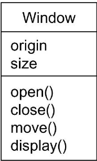
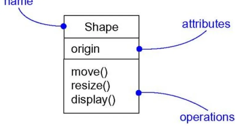
First, a class is a description of a set of objects that share the same attributes, operations, relationships, and semantics. A class implements one or more interfaces. Graphically, a class is rendered as a rectangle, usually including its name, attributes, and operations, as in Figure 2- 1.
Interfaces are discussed in Chapt er 11.
Second, an interface is a collection of operations that specify a service of a class or component. An interface therefore describes the externally visible behavior of that element. An interface might represent the complete behavior of a class or component or only a part of that behavior. An interface defines a set of operation specifications (that is, their signatures) but never a set of operation implementations. Graphically, an interface is rendered as a circle together with its name. An interface rarely stands alone. Rather, it is typically attached to the class or component that realizes the interface, as in Figure 2- 2.
Figure 2-2 Interfaces
Collaborations are discussed in Chapt er 27.
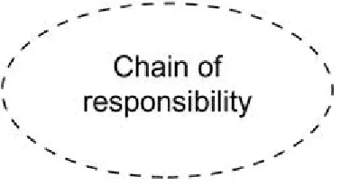
Third, a collaboration defines an interaction and is a society of roles and other elements that work together to provide some cooperative behavior that's bigger than the sum of all the elements. Therefore, collaborations have structural, as well as behavioral, dimensions. A given class might participate in several collaborations. These collaborations therefore represent the implementation of patterns that make up a system. Graphically, a collaboration is rendered as an ellipse with dashed lines, usually including only its name, as in Figure 2- 3.
Use cases are discussed in Chapt er 16.
Fourth, a use case is a description of set of sequence of actions that a system performs that yields an observable result of value to a particular actor. A use case is used to structure the behavioral things in a model. A use case is realized by a collaboration. Graphically, a use case is rendered as an ellipse with solid lines, usually including only its name, as in Figure 2- 4.
Figure 2-4 Use Cases
The remaining three things•active classes, components, and nodes•are all class-like, meaning
they also describe a set of objects that share the same attributes, operations, relationships, and semantics. However, these three are different enough and are necessary for modeling certain aspects of an object-oriented system, and so they warrant special treatment.
Active classes are discussed in Chapt er 22.
Fifth, an active class is a class whose objects own one or more processes or threads and therefore can initiate control activity. An active class is just like a class except that its objects represent elements whose behavior is concurrent with other elements. Graphically, an active class is rendered just like a class, but with heavy lines, usually including its name, attributes, and operations, as in Figure 2- 5.
Figure 2-5 Active Classes
The remaining two elements•component, and nodes•are also different. They represent
Components are discussed in Chapt er 25.
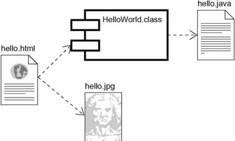
Sixth, a component is a physical and replaceable part of a system that conforms to and provides the realization of a set of interfaces. In a system, you'll encounter different kinds of deployment components, such as COM+ components or Java Beans, as well as components that are artifacts of the development process, such as source code files. A component typically represents the physical packaging of otherwise logical elements, such as classes, interfaces, and collaborations. Graphically, a component is rendered as a rectangle with tabs, usually including only its name, as in Figure 2- 6.
Figure 2-6 Components
Nodes are discussed in Chapt er 26.
Seventh, a node is a physical element that exists at run time and represents a computational resource, generally having at least some memory and, often, processing capability. A set of components may reside on a node and may also migrate from node to node. Graphically, a node is rendered as a cube, usually including only its name, as in Figure 2- 7.
Figure 2-7 Nodes
These seven elements•classes, interfaces, collaborations, use cases, active classes,
components, and nodes•are the basic structural things that you may include in a UML model.
There are also variations on these seven, such as actors, signals, and utilities (kinds of classes), processes and threads (kinds of active classes), and applications, documents, files, libraries, pages, and tables (kinds of components).
Use cases, which are used to structure the behavioral things in a model, are discussed in
Behavioral things are the dynamic parts of UML models. These are the verbs of a model, representing behavior over time and space. In all, there are two primary kinds of behavioral things.
First, an interaction is a behavior that comprises a set of messages exchanged among a set of objects within a particular context to accomplish a specific purpose. The behavior of a society of objects or of an individual operation may be specified with an interaction. An interaction involves a number of other elements, including messages, action sequences (the behavior invoked by a message), and links (the connection between objects). Graphically, a message is rendered as a directed line, almost always including the name of its operation, as in Figure 2- 8.
Figure 2-8 Messages
State machines are discussed in Chapt er 21.
Second, a state machine is a behavior that specifies the sequences of states an object or an interaction goes through during its lifetime in response to events, together with its responses to those events. The behavior of an individual class or a collaboration of classes may be specified with a state machine. A state machine involves a number of other elements, including states, transitions (the flow from state to state), events (things that trigger a transition), and activities (the response to a transition). Graphically, a state is rendered as a rounded rectangle, usually
including its name and its substates, if any, as in Figure 2- 9.
Figure 2-9 States
These two elements•interactions and state machines•are the basic behavioral things that you
may include in a UML model. Semantically, these elements are usually connected to various structural elements, primarily classes, collaborations, and objects.
Grouping Things
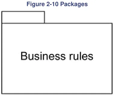
Grouping things are the organizational parts of UML models. These are the boxes into which a model can be decomposed. In all, there is one primary kind of grouping thing, namely, packages.
Packages are discussed in Chapt er 12.
Figure 2-10 Packages
Packages are the basic grouping things with which you may organize a UML model. There are also variations, such as frameworks, models, and subsystems (kinds of packages).
Notes are discussed in Chapt er 6. Annotational Things
Annotational thingsare the explanatory parts of UML models. These are the comments you may apply to describe, illuminate, and remark about any element in a model. There is one primary kind of annotational thing, called a note. A note is simply a symbol for rendering constraints and comments attached to an element or a collection of elements. Graphically, a note is rendered as a rectangle with a dog-eared corner, together with a textual or graphical comment, as in Figure 2- 11.
Figure 2-11 Notes
This element is the one basic annotational thing you may include in a UML model. You'll typically use notes to adorn your diagrams with constraints or comments that are best expressed in informal or formal text. There are also variations on this element, such as requirements (which specify some desired behavior from the perspective of outside the model).
Relationships in the UML
There are four kinds of relationships in the UML: 1. Dependency
2. Association 3. Generalization 4. Realization
Dependencies are discussed in Chapt ers 5 and 10.
First, a dependency is a semantic relationship between two things in which a change to one thing (the independent thing) may affect the semantics of the other thing (the dependent thing). Graphically, a dependency is rendered as a dashed line, possibly directed, and occasionally including a label, as in Figure 2- 12.
Figure 2-12 Dependencies
Associations are discussed in Chapt ers 5 and 10.
Second, an association is a structural relationship that describes a set of links, a link being a connection among objects. Aggregation is a special kind of association, representing a structural relationship between a whole and its parts. Graphically, an association is rendered as a solid line, possibly directed, occasionally including a label, and often containing other adornments, such as multiplicity and role names, as in Figure 2- 13.
Figure 2-13 Associations
Generalizations are discussed in Chapt ers 5 and 10.
Third, a generalization is a specialization/generalization relationship in which objects of the specialized element (the child) are substitutable for objects of the generalized element (the parent). In this way, the child shares the structure and the behavior of the parent. Graphically, a generalization relationship is rendered as a solid line with a hollow arrowhead pointing to the parent, as in Figure 2- 14.
Figure 2-14 Generalizations
Realizations are discussed in Chapt er 10.
Fourth, a realization is a semantic relationship between classifiers, wherein one classifier specifies a contract that another classifier guarantees to carry out. You'll encounter realization relationships in two places: between interfaces and the classes or components that realize them, and between use cases and the collaborations that realize them. Graphically, a realization
relationship is rendered as a cross between a generalization and a dependency relationship, as in Figure 2- 15.
Figure 2-15 Realization
The five views of an architecture are discussed in the following section.
Diagrams in the UML
A diagram is the graphical presentation of a set of elements, most often rendered as a connected graph of vertices (things) and arcs (relationships). You draw diagrams to visualize a system from different perspectives, so a diagram is a projection into a system. For all but the most trivial systems, a diagram represents an elided view of the elements that make up a system. The same element may appear in all diagrams, only a few diagrams (the most common case), or in no diagrams at all (a very rare case). In theory, a diagram may contain any combination of things and relationships. In practice, however, a small number of common combinations arise, which are consistent with the five most useful views that comprise the architecture of a software-intensive system. For this reason, the UML includes nine such diagrams:
1. Class diagram 2. Object diagram 3. Use case diagram 4. Sequence diagram 5. Collaboration diagram 6. Statechart diagram 7. Activity diagram 8. Component diagram 9. Deployment diagram
Class diagrams are discussed in Chapt er 8.
A class diagram shows a set of classes, interfaces, and collaborations and their relationships. These diagrams are the most common diagram found in modeling object-oriented systems. Class diagrams address the static design view of a system. Class diagrams that include active classes address the static process view of a system.
Object diagrams are discussed in Chapt er 14
An object diagram shows a set of objects and their relationships. Object diagrams represent static snapshots of instances of the things found in class diagrams. These diagrams address the static design view or static process view of a system as do class diagrams, but from the perspective of real or prototypical cases.
Use case diagrams are discussed in Chapt er 17.
A use case diagram shows a set of use cases and actors (a special kind of class) and their relationships. Use case diagrams address the static use case view of a system. These diagrams are especially important in organizing and modeling the behaviors of a system.
Interaction diagrams are discussed in Chapt er 18.
Both sequence diagrams and collaboration diagrams are kinds of interaction diagrams. An shows an interaction, consisting of a set of objects and their relationships, including the messages that may be dispatched among them. Interaction diagrams address the dynamic view of a system. A
collaboration diagram is an interaction diagram that emphasizes the structural organization of the objects that send and receive messages. Sequence diagrams and collaboration diagrams are isomorphic, meaning that you can take one and transform it into the other.
Statechart diagrams are discussed in Chapt er 24.
A statechart diagram shows a state machine, consisting of states, transitions, events, and activities. Statechart diagrams address the dynamic view of a system. They are especially important in modeling the behavior of an interface, class, or collaboration and emphasize the event-ordered behavior of an object, which is especially useful in modeling reactive systems.
Activity diagrams are discussed in Chapt er 19.
An activity diagram is a special kind of a statechart diagram that shows the flow from activity to activity within a system. Activity diagrams address the dynamic view of a system. They are especially important in modeling the function of a system and emphasize the flow of control among objects.
Component diagrams are discussed in Chapt er 29.
A component diagram shows the organizations and dependencies among a set of components. Component diagrams address the static implementation view of a system. They are related to class diagrams in that a component typically maps to one or more classes, interfaces, or collaborations.
Deployment diagrams are discussed in Chapt er 30.
A deployment diagram shows the configuration of run-time processing nodes and the
components that live on them. Deployment diagrams address the static deployment view of an architecture. They are related to component diagrams in that a node typically encloses one or more components.
This is not a closed list of diagrams. Tools may use the UML to provide other kinds of diagrams, although these nine are by far the most common you will encounter in practice.
Rules of the UML
The UML's building blocks can't simply be thrown together in a random fashion. Like any
language, the UML has a number of rules that specify what a well-formed model should look like. A well-formed model is one that is semantically self-consistent and in harmony with all its related models.
The UML has semantic rules for
Names What you can call things, relationships, and diagrams Scope The context that gives specific meaning to a name Visibility How those names can be seen and used by others Integrity How things properly and consistently relate to one another Execution What it means to run or simulate a dynamic model
Models built during the development of a software-intensive system tend to evolve and may be viewed by many stakeholders in different ways and at different times. For this reason, it is
common for the development team to not only build models that are well-formed, but also to build models that are
Inconsistent The integrity of the model is not guaranteed
These less-than-well-formed models are unavoidable as the details of a system unfold and churn during the software development life cycle. The rules of the UML encourage you•but do not
force you•to address the most important analysis, design, and implementation questions that
push such models to become well-formed over time.
Common Mechanisms in the UML
A building is made simpler and more harmonious by the conformance to a pattern of common features. A house may be built in the Victorian or French country style largely by using certain architectural patterns that define those styles. The same is true of the UML. It is made simpler by the presence of four common mechanisms that apply consistently throughout the language.
1. Specifications 2. Adornments 3. Common divisions 4. Extensibility mechanisms Specifications
The UML is more than just a graphical language. Rather, behind every part of its graphical notation there is a specification that provides a textual statement of the syntax and semantics of that building block. For example, behind a class icon is a specification that provides the full set of attributes, operations (including their full signatures), and behaviors that the class embodies; visually, that class icon might only show a small part of this specification. Furthermore, there might be another view of that class that presents a completely different set of parts yet is still consistent with the class's underlying specification. You use the UML's graphical notation to visualize a system; you use the UML's specification to state the system's details. Given this split, it's possible to build up a model incrementally by drawing diagrams and then adding semantics to the model's specifications, or directly by creating a specification, perhaps by reverse engineering an existing system, and then creating diagrams that are projections into those specifications. The UML's specifications provide a semantic backplane that contains all the parts of all the models of a system, each part related to one another in a consistent fashion. The UML's
diagrams are thus simply visual projections into that backplane, each diagram revealing a specific interesting aspect of the system.
Notes and other adornments are discussed in Chapt er 6. Adornments
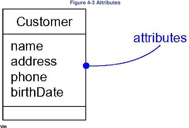
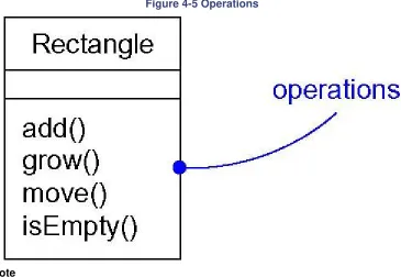
Most elements in the UML have a unique and direct graphical notation that provides a visual representation of the most important aspects of the element. For example, the notation for a class is intentionally designed to be easy to draw, because classes are the most common element found in modeling object-oriented systems. The class notation also exposes the most important aspects of a class, namely its name, attributes, and operations.
A class's specification may include other details, such as whether it is abstract or the visibility of its attributes and operations. Many of these details can be rendered as graphical or textual adornments to the class's basic rectangular notation. For example, Figure 2- 16 shows a class, adorned to indicate that it is an abstract class with two public, one protected, and one private operation.
Every element in the UML's notation starts with a basic symbol, to which can be added a variety of adornments specific to that symbol.
Common Divisions
In modeling object-oriented systems, the world often gets divided in at least a couple of ways.
Objects are discussed in Chapt er 13.
First, there is the division of class and object. A class is an abstraction; an object is one concrete manifestation of that abstraction. In the UML, you can model classes as well as objects, as shown in Figure 2- 17.
Figure 2-17 Classes And Objects
In this figure, there is one class, named Customer, together with three objects: Jan (which is marked explicitly as being a Customer object), :Customer (an anonymous Customer object), and Elyse (which in its specification is marked as being a kind of Customer object, although it's not shown explicitly here).
Almost every building block in the UML has this same kind of class/object dichotomy. For example, you can have use cases and use case instances, components and component
instances, nodes and node instances, and so on. Graphically, the UML distinguishes an object by using the same symbol as its class and then simply underlying the object's name.
Second, there is the separation of interface and implementat