A MULTI-DATA SOURCE AND MULTI-SENSOR APPROACH FOR THE 3D
RECONSTRUCTION AND VISUALIZATION OF A COMPLEX ARCHAELOGICAL
SITE: THE CASE STUDY OF TOLMO DE MINATEDA
J.A. Torres-Martínez a *, M. Seddaiu b, P. Rodríguez-Gonzálvez a, D. Hernández-López c, D. González-Aguilera a
a
Department of Cartographic and Land Engineering; High School of Ávila, University of Salamanca, Ávila, Spain – (josealberto,pablorgsf, daguilera)@usal.es
b
Dipartimento di Storia, Scienze dell' Uomo e della Formazione, Università degli Studi di Sassari, Sassari, Italy - [email protected]
c
Regional Development Institute-IDR, University of Castilla-La Mancha, Albacete, 02071, Spain - [email protected]
Commission V, WG V/4
KEY WORDS: Reconstruction, Multisensor, Aerial Photogrammetry, Laser scanning, Computer vision, Archaeology.
ABSTRACT:
The complexity of archaeological sites hinders to get an integral modelling using the actual Geomatic techniques (i.e. aerial, close-range photogrammetry and terrestrial laser scanner) individually, so a multi-sensor approach is proposed as the best solution to provide a 3D reconstruction and visualization of these complex sites. Sensor registration represents a riveting milestone when automation is required and when aerial and terrestrial dataset must be integrated. To this end, several problems must be solved: coordinate system definition, geo-referencing, co-registration of point clouds, geometric and radiometric homogeneity, etc. Last but not least, safeguarding of tangible archaeological heritage and its associated intangible expressions entails a multi-source data approach in which heterogeneous material (historical documents, drawings, archaeological techniques, habit of living, etc.) should be collected and combined with the resulting hybrid 3D of “Tolmo de Minateda” located models. The proposed multi-data source and multi-sensor approach is applied to the study case of “Tolmo de Minateda” archaeological site. A total extension of 9 ha is reconstructed, with an adapted level of detail, by an ultralight aerial platform (paratrike), an unmanned aerial vehicle, a terrestrial laser scanner and terrestrial photogrammetry. In addition, the own defensive nature of the site (i.e. with the presence of three different defensive walls) together with the considerable stratification of the archaeological site (i.e. with different archaeological surfaces and constructive typologies) require that tangible and intangible archaeological heritage expressions can be integrated with the hybrid 3D models obtained, to analyse, understand and exploit the archaeological site by different experts and heritage stakeholders.
* Corresponding author.
1. INTRODUCTION
Several techniques have been applying so far for the 3D reconstruction and visualization of archaeological settlements based on the use of aerial or close-range photogrammetry (Gomez-Lahoz and Gonzalez-Aguilera, 2009), or using terrestrial laser scanner (Gonzalez-Aguilera et al., 2011). However due to the inherent complexity of these sites, a multi-sensor approach is preferred for the 3D reconstruction and visualization of these environments (Torres et al., 2014). The goal of this study is to propose a multi-data source and multi-sensor workflow in order to obtain high quality archaeological products. To this end, terrestrial scans and images will be registered with aerial images acquired from a paratrike and an unmanned aerial vehicle (UAV).
The application the aforementioned workflow was carried out in the archaeological site in Albacete (Spain). This settlement is characterized by the presence of a monumental defensive system sited in the area denominated as “El Reguerón” that encloses three defensive walls of different chronological and architectural nature. Furthermore, the relevant archaeological stratification of this area with different structures and building types requires of a multi-data source and multi-sensor approach that allows us to properly record and classify archaeological surfaces establishing an integration of topographic data with documents of archaeological excavations.
To carry out studies of characterization, measurement and analysis of the surface and the elements presented in the site, the geometrical information (acquired with geomatic sensors) is combined with other available thematic data such as, photographs, sketches, restorations reports, schedules, etc. in a 3D geographical information system (3DGIS). By this way a description of the site through time is possible.
In order to fulfill the archaeological documentation requirements, the aerial data gathering was performed with a paratrike which allows us to enclose the whole extension of the archaeological site using a full frame reflex camera and assisted by a specific gyrostabilized platform (MUSAS-MUltiSpectral Airborne Sensors) with a ground sample distance (GSD) of 3 cm. Trying to record with higher spatial resolution the area of interest of the site, “El Regueron”, an UAV with an ultra-compact camera acquired the fortified walls with a GSD of 1 cm.
Both flight planning (paratrike and UAV) were carried out based on the classical aerial photogrammetric principles (Kraus, 1993). The in-house software MFlip and PFlip (Hernandez-Lopez et al., 2013) were used for flight planning and control. Considering the important topographic relief of the site, special attention was focused on the GSD variation (i.e. scale) during flight, guarantying a level of detail adapted to the archaeological work. In addition, to increase the level of detail in the fortification walls and thus avoid the occlusions due to The International Archives of the Photogrammetry, Remote Sensing and Spatial Information Sciences, Volume XL-5/W4, 2015
the effects of terrain relief (i.e. areas occluded or without information in the model generated by aerial photogrammetry), a combination of terrestrial photogrammetry and terrestrial laser scanner (TLS) was employed for improving the final 3D hybrid model.
This paper is organized as follows: after this introduction, in section 2, the different sensors employed and their characteristics are detailed. In section 3, the proposed multi-data source and multi-sensor approach is described. Experimental results are shown and discussed in section 4. Conclusions and future directions are given in section 5.
2. MATERIALS 2.1 Paratrike
The main aerial platform employed to the documentation of the archaeological area was a paratrike (Figure 1, up-left). It is a low-cost aircraft with more flexibility than conventional aircrafts, and more autonomy and payload capacity than the UAVs. This last characteristic allows the possibility of boarding better sensors than the UAVs, or even multiple sensors in a stabilized gimbal (MUSAS).
Motor Rotax 503 two-stroke
Trike Tandem Trike AIRGES
Tandem paraglide MAC PARA Pasha 4 Emergency system Ballistic parachutes
Weight 110 Kg
Weight capability 165-250 Kg or 195-295 Air velocity range 30-60 km/h
Table 1. Technical specifications of the paratrike.
The use of the gyro-stabilized camera platform, MUSAS, guarantees the orientation of the camera according to the flight planning by two servomotors arranged on the x and y axes, controlled by an Arduino board, which incorporates an IMU with 6 degrees of freedom: 3 accelerometers, a double-shaft gyroscope (for pitch and roll) and an additional gyroscope for yaw.
2.2 Unmanned Aerial Vehicle
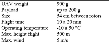
For the aerial photogrammetric acquisition in the “El Reguerón” site, the paratrike platform was rejected due to the morphological characteristics of the terrain and the height of flight required to reach the high spatial resolution (GSD of 1 cm). The main drawback was the need to vary the flying height to keep the same scale, due to the presence of high relieves along the strips. As additional disadvantage, the walled constructions were occluded between walls of natural rock. Therefore, in order to complete the archaeological site documentation, an UAV was employed. Concretely, a Microdrone md4-200 was used (Figure 1, down).
UAV weight 900 g
Payload up to 200 g
Size 54 cm between rotors
Flight time 10 a 20 min Operating temperature -10 a 50 °C Max. height flight 500 m
Max. wind 5 m/s
Table 2. Technical specifications of the Microdrone md4-200 platform.
In spite of the manoeuvrability provided by this UAV, its limited payload required to employ a compact camera for the photogrammetric flight. The flight was planned according to the boarded camera technical specifications (see section 2.3) using the MFlip in-house software.
2.3 Cameras
According to the different methodologies and platforms used, two different cameras were employed:
For the paratrike, a full frame reflex camera, Canon 5D MkII, with a fixed focal length to achieve a GSD of 3 cm, was used (Table 3). This camera was also used for the terrestrial photogrammetry and photorealistic texture mapping due to its better image quality.
Sensor type: CMOS
Sensor size: 36 x 24 mm
Image size: 5616 x 3744 pixels
Resolution: 21.1 Mp
Radiometric resolution: 14 bits
Pixel size: 6.4 m
Size 152 × 114 × 75 mm
Weight 810 g (without battery)
Focal length: 50 mm (fixed)
Table 3. Technical specifications of the full-frame camera, Canon 5D MkII.
For the UAV, an ultra-compact camera, Canon IXUS 115 HS (Table 4), was chosen allowing a GSD of 1 cm.
Sensor type: BSI-CMOS
Sensor size: 6.17 x 4.55 mm Image size: 4000 x 3000 pixels
Resolution: 12.1 Mp
Radiometric resolution: JPEG compression
Pixel size: 1.5 m
Size 93 × 56 × 20 mm
Weight 140 g (battery included)
Focal length: 4.9 – 20 mm (28 – 112 mm equivalent)
Table 4. Technical specifications of the compact camera, Canon IXUS 115 HS.
2.4 Terrestrial laser scanner
In those complex zones a phase shift terrestrial laser scanner, Faro Focus 3D, was employed (Table 5).
Model Faro Focus 3D
Principle Phase Shift
Wavelength 905 nm (Near infrared) Field of view 360 ºH x 320 ºV Range std. deviation 2 mm at 25m Measurement range 0.19 mrad Beam divergence 8 mm a 50 m Scanning speed 976,000 points/s
Table 5. Technical specifications of TLS, Faro Focus 3D. The International Archives of the Photogrammetry, Remote Sensing and Spatial Information Sciences, Volume XL-5/W4, 2015
According to the archaeological settlement characteristics and the TLS technical specifications, laser stations were established in a network that guaranteed an average spatial resolution of 5 mm for the whole scenario. The mean distance acquisition was 15 m.
2.5 Navigation system
In contrast to the UAV platform which encloses an integrated navigation system (GPS, IMU and barometric altimeter), the paratrike requires an external set of sensors in order to provide navigation capabilities and thus fulfill photogrammetric constraints for data acquisition. In particular, the planimetric position is provided by a GPS antenna (Trimble Bullet III), installed in the camera platform close to the optical centre of the camera, connected to a mono-frequency receiver Ublox EVK-6T-0. This system yields an absolute precision of ±9 m on the horizontal axis for 95% of the time (Takasu, 2009). During data acquisition the pilot follows the planned photogrammetric mission in a rugged tabled connected to the GPS system, where the real time track is showed against the planned flight. The final component in the navigation system, the altimetry, which affects the GSD, is controlled by an altimetric barometer (DigiFly VL100) with an absolute precision of ±8 m. This solution is chosen instead of GPS receiver, since the absolute GPS precision is just ±15 m.
2.6 Geo-referencing system
The establishment of the mapping frame in the study area is performed with two GNSS bi-frequency (L1, L2) receivers, Topcon manufacturer. The GNSS observation method was real time kinematic (RTK) getting a precision of 1 cm.
The coordinate reference system was the official coordinate system established by the Spanish law (ETRS89); and the cartographic projection UTM in the 30N zone (EPSG: 25830). This mapping frame was materialized by a GNSS surveying using natural features, which could be clearly identified on aerial images (e.g. corners of well-defined objects, small features with great contrast, etc.).
Figure 1. Paratrike employed (up-left); detail of the stabilization platform “MUSAS” (up-right) and UAV used in those complex areas
(down).
3. METHODOLOGY
Given the complexity of the archaeological site and the archaeological documentation requirements, the aerial and
terrestrial data acquisition were planned in order to provide an integral and integrated recording of the site.
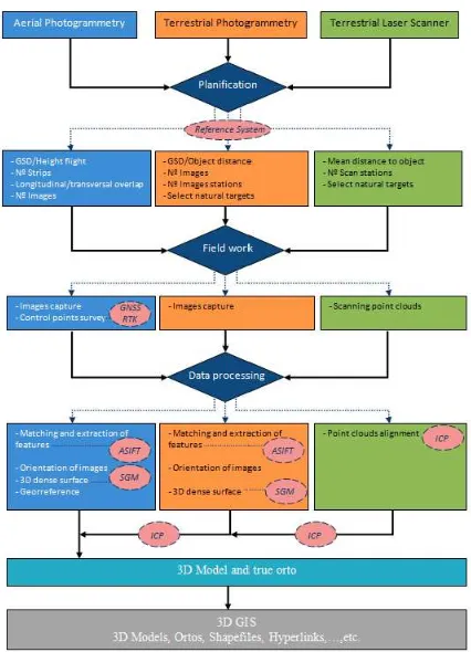
All the data from the different sensors and plataforms were processed according to the workflow outlined in Figure 2 and explined in the following subsections.
Figure 2. Multi-sensor and multi-data source workflow for the 3D reconstruction of complex archaeological sites.
3.1 Data acquisition
Each technique (i.e. photogrammetry, laser scanning) requires different procedures and protocols for data acquisition.
In the case of aerial data acquisition, image projection centers and camera attitude must be previously defined according to the classical photogrammetric parameters. The flight planning was done using the in-house software; MFlip and PFlip, for the UAV and paratrike flights, respectively (Hernandez-Lopez et al., 2013). The main difference between both flights was the type of flight planning: for the paratrike, a classical stereoscopic photogrammetric flight was done, whereas for the case of UAV, oblique images were also considered.
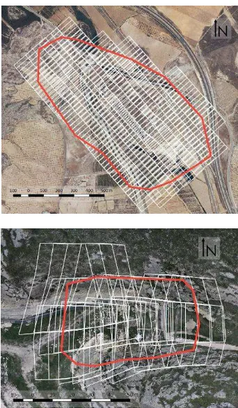
Since the whole archaeological site (9 ha) must be recorded with a 3 cm resolution, paratrike was used due to the autonomy limitations of the UAV. According to the GSD desired for the whole archaeological site (3 cm) and considering the camera specifications (Table 3), a maximum flight height of 224 m was established (Figure 3 up). As result, a total of 268 images along 7 strips (NW-SE direction) were required for guarantying a side overlap >30% and a forward overlap >70%.
Figure 3. Images footprints projected over terrain for the 3 cm GSD flight (up) and the 1 cm GSD flight (down).
For the “El Reguerón” area a more detailed flight with the UAV was designed using the ultra-compact camera (Table 4).The terrain relief effect is showed in the Figure 3 (down), where 25 images and a flight height of 32 m guarantee the desired spatial resolution. The overlap parameters were the same.
An important issue for the aerial data acquisition was the image sharpness, which affects the final photogrammetric reconstruction. This issue is affected by the camera parameters (i.e. aperture, shutter time and sensibility), the platform performance (i.e. flight speed and efficiency of the stabilized gimbal to absorb the paratrike vibrations) and the scenario illumination conditions. The flight was executed in a cloudy day to avoid shadows projected, and the camera sensibility and shutter time were setup for these conditions. The aperture and the focal length were fixed constant to avoid variations in the internal camera parameters.
As it was commented previously, the high vertical relieves of the site and the level of detail required in some areas (e.g. those constructive elements that integrate the defensive system of the entrance, details of the walls, etc.) entailed that aerial images were not suitable; so terrestrial images were acquired with the full-frame reflex camera. As a result, a total of 36 oblique images were acquired in order to avoid areas without information, guarantying a sub-centimeter resolution. In addition, terrestrial laser scans were used in those complex areas where photogrammetry could entails problems, requiring a lot of images to enclose the whole geometry or due to the presence of textureless objects or materials. In particular, a network of 12 TLS stations (Figure 4) was designed for an average distance of 15 m with an average spatial resolution of 5 mm.
Figure 4. TLS stations distribution.
3.2 Data processing
3.2.1 TLS alignment: The raw TLS scans were filtered removing noise and undesired information (e.g. vegetation) which could affect the alignment process. Since artificial targets were not used, scans alignment was done by a solid rigid transformation of an iterative closest point (ICP) technique (Besl and McKay, 1992). This iterative process was applied in pairwise stations, so the final a priori error was computed in the basis of the number of stations and the technical specifications of the TLS (Table 5) reaching 1.3 cm for the assumption of two consecutive overlapping point clouds.
3.2.2 Photogrammetric processing: The generation of the dense point cloud, from both aerial and terrestrial images, was automatized through the Photogrammetry Workbench (PW) in-house software, following a three step workflow: image matching, camera orientation and dense model generation.
The aerial images, coming from the paratrike and UAV, were processed to generate a hybrid model, with a total of 293 images and two different cameras. The dataset was checked to assure the sharpness of the images, which could be decreased by the motion blur.
Firstly, the image matching was solved by the ASIFT - Affine Scale Invariant Feature Transform (Morel and Yu, 2009) algorithm, which is robust to the image perspective variations by an affine transformation:
cos sin 0 cos sin
sin cos 0 1 sin cos
a b k k t
A
c d k k
(1)
Where the affine transformation (A) is composed by a scale factor (), the three angles variation, being and the roll and yaw angles, while the tilt (φ) is defined as φ = arcos (1/t).
In order to accelerate the process, the overlapped aerial images were identified by their approximate camera orientations provided by the navigation system. In the case of terrestrial images, an all-to-all comparison was applied. This sub-step is a time consuming process which increases exponentially with the number of images (Rieke-Zapp and Nearing, 2005).
Secondly, camera orientations were computed by Apero module (Pierrot-Deseilligny and Clery, 2011) using the tie-points obtained in the previous step. In this process the external camera parameters (position and attitude) and the internal camera parameters (self-calibration) were obtained. For the internal camera parameters, the corrections to apply in the collinearity equation (x, y) were defined according to the simplified Fraser model (Fraser et al., 1995) (Pierrot-Deseilligny and Clery, 2011).
distortion coefficients, (p1, p2) the tangential ones and (x´, y´) the image coordinates referred to the principal point.Finally, a dense 3D model was obtained by means of ray intersection (Kraus, 2007) (Pierrot-Deseilligny and Clery, 2011). To solve this process, a SGM (Semi-Global Matching) technique (Hirschmuller, 2008) was applied. In order to provide metric capabilities to the model, scaling was defined through the manual identification of ground control points (GCPs) in the images and solving a Helmert 3D transformation of seven parameters.
3.2.3 Data fusion: The remaining step is the registration of point clouds derived from the different sensors under the same coordinate system. Firstly, a GNSS campaign of 3 hours based on 3 permanent ERGNSS stations was performed in order to provide precise coordinates to the GNSS base station used in the archaeological settlement. Secondly, GNSS observations were processed guarantying an absolute error of 3 cm. Thirdly, the RTK surveying of the GCPs where corrected to obtain the final coordinates of the 3D model integrated under the same coordinate system, reaching a final relative precision of 1 cm. Finally, the ICP technique was employed to transfer the global coordinate reference system from the geo-referenced aerial point cloud (based on GNSS observations) to the TLS point cloud.
3.2.4 Post-processing: Once the metric and geo-referenced point cloud was generated, a triangulation strategy was applied to generate the digital surface model (DSM). More concretely, the incremental Delaunay algorithm was applied (Bourke, 1989).
To improve the model quality, break lines were incorporated as geometric constraints. Break lines were manually restituted by the operator. Its use is relevant for the accurate representation of significant slope changes, as well as for correctly defining the defensive walls of the site. In those cases where images come from different methodologies or acquisition time, it was necessary a radiometric adjustment, to improve the final model visualization and avoid abrupt radiometric changes in the texture.
Once the DSM was obtained, it was possible to generate an orthoimage from the oriented images. Since multi-data source and multi-senor approach provide different DSM resolutions, it was possible to generate orthoimages with different spatial resolutions. For instance, an orthoimage that depicts the complete archaeological site was generated with a resolution of 10 cm; whereas a 2 cm spatial resolution was employed for the
settlement entrance area in order to appreciate the construction features.
4. EXPERIMENTAL RESULTS 4.1 Area of study
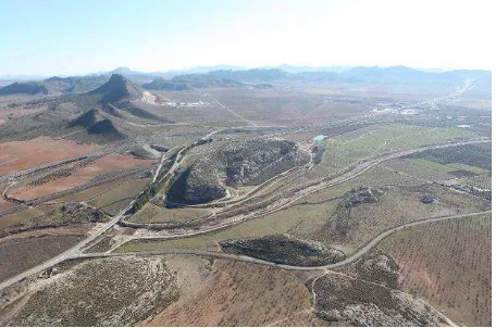
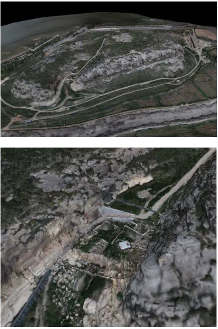
The city of “Tolmo de Minateda” (Figure 5) was a strategic settlement of great importance for several centuries, largely because of its peculiar topography and geographical location. It is placed in a plateau hill of about 50 m of height, located at the junction of the route from Complutum to Carthago Nova, one of the principal Roman route that connect the interior of the Plateau with the southeast coast, and a road that connected Castulo with Saetabis.
Figure 5. Aerial view of the study area “Tolmo de Minateda” (from Abad Casal et al., 2012).
The archaeological research developed in the last 30 years has highlighted the importance of this site: from the Middle Bronze Age, through the Iberian era, the Roman period, the Middle Ages to the twentieth century. The Middle Age period provided most of the information by an important Visigoth settlement located in the upper part of the “El Tolmo”, where was found between houses and cemeteries, an important Christian basilica. One of the most interesting areas of the archaeological site is the called “El Reguerón” (Figure 6); an area of natural drainage of 12 m width, which had the main entrance to the top of the hill where the city was located. In the settlement an important fortification system consisting of three walls of different chronology and architectural typology has been documented. The oldest fortification is represented by the so-called "embanked" wall and was built during the final phase of the Iberian period (IV-II B.C.). Currently, only remains a wall of 6 m of height and 10 m width in the top, embanked in the external front and built in irregular masonry work stuck with soil. During the archaeological works in this ancient wall, an earlier phase, which dates back to the middle Bronze Age, was found. The Iberian wall was successively used as a retaining wall for a new fortification building during Roman times when the “Tolmo de Minateda” probably received the title of municipality.
During the period of peninsula occupation by the Visigoth (V-VI A.D.) is referred the last fortification found in “El Reguerón”. This wall is presented as solid bulwark with L-shape that closes the valley and flanking the main road access to the city. At this point was located a monumental gate probably formed by two solid towers of blocks of which are now only partial remains are preserved. The wall is formed by a The International Archives of the Photogrammetry, Remote Sensing and Spatial Information Sciences, Volume XL-5/W4, 2015
lining blocks with inscriptions and architectural elements from older constructions (among which are from Roman period).
Figure 6. Location of the defensive area “El Reguerón”.
4.2 Workflow
The application of the multi-data source and multi-sensor fusion workflow was tested in the study area of “Tolmo de Minateda”, which includes a total of 9 ha.
The aerial images were processed by the automated photogrammetric approach and the cameras were self-calibrated according to equation (2) as is showed in Table 6.
The raw reconstructed 3D model contains 4,271,354 points, while the TLS integrated point cloud reaches up to 1,314,136 points.
Full frame reflex Canon 5D
Ultra-compact Canon IXUS 115
f (mm) 52.80 6.70
x0(mm) 18.18 3.07
y0 (mm) 12.18 2.23
k1 -5.04 x10⁻⁵ -2.00 x10⁻³
k2 1.79 x10⁻⁸ -6.25 x10⁻⁵
k3 9.78 x10⁻¹² 3.56 x10⁻⁶
p1 -1.32 x10
-5
-5.81 x10⁻⁴
p2 -6.79 x10⁻⁵ -1.41 x10⁻⁴
Table 6. Internal orientation parameters of the cameras boarded in the aerial platforms.
The geo-referencing of the 3D model was solved by the employment of 28 control points homogeneously distributed in the site (but with higher density in the interest area), while 10 were used as check points.
The final multi-resolution 3D model after triangulation is showed in Figure 7, enclosing the whole study area with a
spatial resolution of 3 cm. A total of 10,542,505 triangles were obtained.
For the detailed area which integrates different data sources (i.e. terrestrial laser scanner and photogrammetry), a spatial filtering of 0.5 cm was applied to avoid areas with excessive point density caused by the different overlaps.
Figure 7. Multi-resolution 3D model of the archaeological settlement (up). Detailed 3D model of the “Reguerón” (down).
By this multi-resolution approach, the final inspection of the archaeological site could be adapted to any area, as is showed in the interest area of “El Reguerón”, where the subcentimeter resolution achieved for the walls and construction (Figure 8 down) was integrated with the rest of the archaeological site (Figure 8 top). This multi-resolution capability opens a range of possibilities for a spatial analysis, settlement interpretation, patterns recognition, and the establishing relationships among the elements (sites, artefacts locations, etc.).
Figure 8. Multi-resolution model of “El Reguerón” area (up) and detail for the wall (down).
In order to validate the final integration of the different data source, a series of check points were used. The different error components are showed in Table 7. The average altimetric error (1.4 cm) was higher than the planimetric error, as was expected for the GNSS technique. An average precision of 4.1 cm for the 3D vector error was obtained, which is statistical compatible with the expected error of 4.2 cm composed by the model and GNSS check point errors.
Check points Discrepancies with 3D model coordinates X (m) Y (m) H (m) ∆X (m) ∆Y (m) ∆H (m) 621321.452 4259638.120 448.672 0.035 0.016 -0.013 621375.933 4259646.226 454.775 -0.019 0.044 0.002 621416.258 4259667.686 463.661 0.027 -0.011 0.030 621419.022 4259658.232 464.618 0.001 0.028 0.046 621345.185 4259659.272 454.267 0.022 0.006 0.004 621321.298 4259660.311 452.106 -0.010 -0.033 0.016
Table 7. Geo-referencing errors.
To manage more efficiently the available information of the archaeological settlement, orthoimages were generated as derived products (Figure 9), since they combined the photorealistic texture with the metric properties in an easy to use document for non-experts.
Figure 9. Orthoimages of the whole settlement (up) and defensive area “El Reguerón” (down).
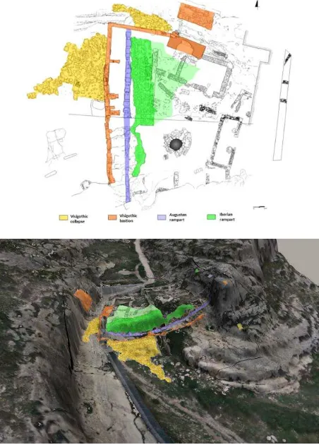
However, to allow a more complete interpretation and to make use of the potential of the generated 3D product, an integration with a 3DGIS tool, GeoWeb3D, was done. In particular, the 3D geometry provided by the multi-sensor approach has been integrated with 2D archaeological archives such as sketches, pictures, part details, etc. enhancing the subsequent analysis, and providing problem solving and taking decision capabilities.. In Figure 10 is showed the integration of different historical events over the 3D model reconstructed.
Figure 10. Archaeological sketch (up) overlapped with the 3D model (down).
5. CONCLUSIONS
This paper presents a methodology based on a combination of multiple sensors, platforms and techniques, which has been tested in a complex archaeological site. As is shown in the experimental results, the automation provided by the photogrammetric and laser techniques, along with the versatility of the aerial platforms (paratrike and UAV), provide the suitability of this methodology for complex archaeological sites.
The potential of ultralight aerial platforms (paratrike) is highlighted, due to its payload and flight autonomy, which overpasses the UAVs capabilities. Regarding the usual archaeological surveys, one of the main differential factors in this work has been the integration of aerial images at different resolutions, terrestrial images and terrestrial laser scans.
The generation of high resolution products based on photogrammetry requires high computational costs. To this end, the presented algorithms, such as ASIFT, have been developed taking advance of GPU capabilities, reducing time operations and consequently improving the workflow efficiency.
The management of the final models through a 3DGIS tool opens new analysis capabilities for the archaeologist (e.g. analysis though time, archaeological investigations, integration of historical and geometric models).
The data acquisition and processing methodologies from Geomatic science broaden the possibilities of sensors, configurations and/or combination as future perspectives. Concretely, the resolution of the external orientation of the images directly, just using the integrated GNSS/IMU of the aerial platform, would allow us to speed up the field work and processing time. Furthermore, in order to obtain realistic textured models and orthoimages, the use of techniques such BRDF (Bidirectional Reflectance Distribution Function) to improve the radiometric parameters will be studied.
ACKNOWLEDGEMENTS
This research has been developed in the framework of the research project “Infraestructura de datos espaciales de patrimonio arqueológico de Castilla-La Mancha” (POII-2014-004-P) of the 2014-2017 Scientific Research Projects cofounded by the European Regional Development Fund. The authors would like to thank the Ministry of Education, Culture and Sport of Castilla-La Mancha, especially to the Directorate-General for Universities, Research and Innovation, the Directorate-General for Cultural and the Museum of Albacete.
REFERENCES References from Books:
Kraus, K., 2007. Photogrammetry: geometry from images and laser scans. Walter de Gruyter. Berlin, Germany.
References from Journals:
Abad Casal, L., Gutierrez Lloret, S., Gamo Parras, B., Canovas Guillen, P., 2012. El Tolmo de Minateda (Hellín, Albacete,
España): un proyecto de investigación y puesta en valor del patrimonio. Debates de arqueología medieval, 2, pp. 351-381.
Besl, P., McKay, N., 1992. A method for registration of 3-D Shapes. IEEE transactions on pattern analysis and machine intelligence, 14(2), pp. 239-256.
Gomez-Lahoz, J., Gonzalez-Aguilera, D., 2009. Recovering traditions in the digital era: the use of blimps for modelling the archaeological cultural heritage. Journal of archaeological science, 36(1), pp. 100-109.
González-Aguilera, D., Muñoz-Nieto, Á., Rodríguez-Gonzálvez, P., Menéndez, M., 2011. New tools for rock art modelling: Automated sensor integration in Pindal cave. Journal of archaeological science, 38(1), pp. 120-128.
Hernandez-Lopez, D., Felipe-Garcia, B., Gonzalez-Aguilera, D., Arias-Perez, B., 2013. An automatic approach to UAV flight planning and control for photogrammetric applications: a test case in the Asturias region (Spain), Photogrammetric engineering and remote sensing, 79, pp. 87-98.
Hirschmuller, H., 2008. Stereo processing by semiglobal matching and mutual information. IEEE transactions on pattern analysis and machine intelligence, 30, pp. 328-341.
Morel, J.M., Yu, G., 2009. ASIFT: A new framework for fully affine invariant image comparison. SIAM journal on imaging sciences, 2(2), pp. 438-469.
Rieke-Zapp, D.H., Nearing, M.A., 2005. Digital close range photogrammetry for measurement of soil erosion. Photogrammetry record, 20, pp. 69-87.
Torres, J.A., Hernandez-Lopez, D., Gonzalez-Aguilera, D., Moreno Hidalgo, M.A., 2014. A hybrid measurement approach for archaeological site modelling and monitoring: the case study of Mas D'is, Penàguila. Journal of archaeological science, 50, pp. 475-483.
References from Other Literature:
Bourke, P., 1989. An algorithm for interpolating irregularly-spaced data with applications in terrain modelling. In: Pan pacific computer conference, Beijing, China. 6 pages.
Fraser, C.S., Shortis, M.R., Ganci, G., 1995. Multisensor system self-calibration. In: SPIE conference 2598, Videometrics IV, Philadelphia, USA, pp. 2-18.
Pierrot-Deseilligny, M., Clery, I., 2011. Apero, an open source bundle adjusment software for automatic calibration and orientation of set of images. In: 3DARCH’11, Trento, Italy, pp. 269-276.
Takasu T., 2009. RTKLIB: Open source program package for RTK-GPS, FOSS4G 2009 Tokyo, Japan.