Eliminating and Modelling Non-metric Camera Sensor Distortions Caused by Sidewise and
Forward Motion of the UAV
Mirahmad Chabok [email protected]
Dronemetrex Ltd. South Australia, Adelaide
Flinders University, School of the Environment, South Australia, Adelaide
KEY WORDS: UAV Photogrammetry, Motion Compensation, Distortion and Blur, Quick Processing
ABSTRACT:
This paper explains the critical importance of modelling and eliminating the effect of motion of an Unmanned Aerial Vehicle (UAV) as a result of air turbulence and unstable flight conditions on a camera sensor and the image geometry. A new method for improving the geometrical distortions caused by this motion is introduced. We have developed a hardware and software tool to minimize and model the geometric distortion of the image from commercial off-the-shelf (COTS) cameras which are commonly being used in aerial mapping UAVs. Due to the rolling shutter mechanism of the most common SLR cameras, sideway and forward motions of the UAV during image capture will have a strong effect on the image geometry and final product accuracies. As the amount of this random distortion varies from one photo to the next, a unique and robust camera calibration model cannot be established for interior orientation and image processing using photogrammetric methods, even by self-calibration. To achieve the highest possible accuracy, we also consider temperature effects on the camera calibration parameters. In this paper we show the results, accuracies and benefits of using this method compared with a typical UAV mapping system. To the best of our knowledge this is the first time that this method has been implemented in a UAV mapping system.
1. INTRODUCTION
Random geometric distortions on each individual photo will produce non-reliable, non-repeatable and inaccurate results irrespective of the kind and make of the software used for photogrammetric computations. The main reason for such distortions are sideways and forward motion of the camera during the exposure time by implementing a low weight robotic stabilized Camera Mount (CM) which compensates for Pitch, Roll and Yaw angles in a high vibration environment. (see Figure 1c). The CM receives the rotational corrections from the IMU with one degree resolution as well as the drift angle from a digital compass with two degree resolution and keeps the camera sensor aligned with the flight direction and nadir position which means that, the camera axis at triggering points will always be parallel (see Figure 2a) to the flight path. By doing so, the rolling shutter effect and pixel distortions will be aligned with the flight direction (see Figure 1c). Secondly, we estimate the Point Spread Function (PSF) which now has only one linear direction and is thus less complicated to estimate. Estimating the PSF with sub-pixel accuracy is very crucial to avoid un-desired effects. For sub-pixel PSF estimation we use the camera shutter speed and ground speed of the UAV at the time of exposure for each image. Thirdly, we then use the PSF for image deconvolution and for compensation for forward motion. For this purpose a software tool has been developed for automatic PSF calculation from GPS log files and applying the corrections for every single image. Furthermore, because the camera has a non-rigid body, the location of the principal point of the camera, and thus the focal length will vary with temperature. To achieve a stable interior orientation
parameters, we perform the laboratory camera calibration for different temperatures and use the temperature based calibration parameters making use of the recorded actual internal temperature of the UAV. This procedure produces a distortion-free image with robust interior orientation ready to use for photogrammetric computations. At the same time, this method reduces the processing time substantially guaranteeing reliable and repeatable accuracies.
1.1 Related Work
Image motion compensation and the resulting image blur has been addressed in computer vision and image processing industries. Examples are feature tracking based on extracting the 3D motion of the camera [Liu et al.2009], using an Inertial measurement unit (IMU) for image motion de-blurring [Joshi et al.2010, Gruber et.al. 2012] and a mechanical image stabilization system in walking robots [Kurazume and Hirose 2000]. IMU based image de-blurring which has recently been introduced is IMU sensor dependent and suffers in restoring the geometric pixel distortions in a high turbulence flight environment. As Electro Magnetic Interference (EMI) and Radio Frequency Interferences (RFI) in UAVs can upset the IMU output rates and its accuracy, relying on IMU data for estimating the PSF will be unreliable in UAV photogrammetry except when using expensive high end IMUs. In our proposed method we first apply a low pass filter to the IMU data and then use this noise-free IMU data as an input to the CM for angular motion compensation. This method will keep the camera in nadir position, whereas the flight management software applies the drift corrections from the digital compass (See Figure 2a). The effect of temperature changes on the camera calibration parameters is shown in Figure 6 [6].
2. OUR WORKFLOW
Our image acquisition system compensates for side and rotational motion of the UAV during image capture and corrects for the UAV’s crab angle. Therefore there will be no image warp and distortion from rotational movements of the camera and the only remaining issue will be the forward motion compensation and restoring the original un-blurred image.
(f)
(g)
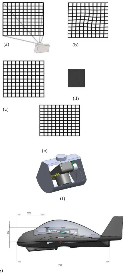
Figure 1: (a) camera sensor exposing the image with rolling shutter, (b) captured photo with side and forward motion of the UAV, image is warped and skewed, (c) captured photo with compensated side and rotational movements of the camera using our proposed method, pixels are stretched only in flight direction, (d) calculated PSF map based on ground and shutter speed, (e) Deconvolved image using generated PSF , image is un-blurred and distortion free, (f) CM with 400 grams net weight including the lens protection door for take-off and landing, (g) CM installed in TopoDrone-100 mapping UAV.
(a)
(b)
Figure 2: (a) shows our method for image acquisition using CM and parallel camera axis in all flight conditions with compensation for crab angle. Photos are taken in pre-designed flight direction with stable overlap, models are parallax free and tie points matching will be accelerated in aerial triangulation. Stereo models can be imported in stereo plotters for 3D feature extractions (b) shows the effect of non-parallel camera axis, captured images are not aligned with pre-designed flight direction and requires large overlaps to full-fill the minimum stereo overlap requirement, tie points matching requires more processing time.
(a) (b)
(c)
(d)
(e)
2.1 Motion Blur Calculation
We estimate the linear blur amount for each photo using
shutter and ground speed which is extracted from the GPS log
file . The motion blur is calculated as follow [5]:
3 ^ 10
i i i i
h c
f t v
L (1)
where for every image (i)
Li = motion size in pixel
vi = linear ground speed for image (i) in km/h at
the time of exposure
ti = exposing time
f = focal length in mm
hi = flying height above ground in meter
c = camera sensor pixel size in micron
In regards to the angular motion, we have logged the actual angular velocity for both UAV and CM during the flight in a stable direct flight path and normal weather condition.
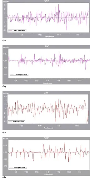
Figure 3a. shows the pitch angle rotation rate of the UAV, the average rotation rate of the UAV is 0.3 rad/s whereas the average rotational speed of the CM is 0.03 rad/s according the Figure 3b. It can be seen in Figures 3c and 3d that the roll rate is almost identical to the pitch rate. The angular velocity of the CM is significantly smaller than that of the UAV which results in less blur from angular motion.
For example, the amount of blur caused from sideways and forward motion of a typical fixed-wing UAV can be calculated as follow with assuming :
Cruise speed: 80 km/h Camera shutter speed: 1/1000 s Camera’s sensor size: 4 micron Focal length: 28 mm
Flying height: 120 m
Using the Equation (1) the forward motion blur will be 4.7 pixels. ( see Figure 4a)
To obtain the side motion blur, using Equation (2) and (3) derived from Figure 4 to convert the angular velocity to linear ground speed, the equivalent linear speed of the UAV in both pitch and roll direction will be 0.3 rad/sec
120m=36 m/s or 129.6 km/h. Using Equation (1), the side motion blur amount will be 7.5 pixels. In our proposed method the linear speed for the CM using Equation (3) is 0.03 rad/s
120m = 3.6 m/s or 12.96 km/h. The blur amount caused is only 0.7 pixels, we only apply the PSF in forward motion direction.
(a)
(b)
(c)
(d)
Figure 3. shows the angular velocity in rad/s at the same time period for : (a) the pitch rate of the UAV, (b) pitch rate of the CM , (c) roll rate of the UAV, (d) roll rate of the CM.
Figure 4. Converting angular speed to linear speed
Depending on turbulence encountered, the angular velocity of the UAV can reach up to 200 /s ( 3.5 rad/s), this means it takes 1.8 s for one revolution which is normal for a typical low weight fixed-wing UAV.
2.2 PSF Calculation
The captured image using our method will only have a forward motion blur in a known direction, Figure 1c, which is convoluted with the PSF as shown in Equation (4).
) the general form of the linear uniform PSF function following [2]: domain and remove the image motion blur with estimated noise variant using the ‘Richardson-Lucy’ iterative de-convolution algorithm [3], which is an iterative procedure for recovering a latent image that has been blurred by a known PSF function[4].
Pixels in the blurred image can be represented in terms of the original image and PSF function as :
Poisson-distributed which is appropriate for photon noise in the data. We use the following iterative equation from [3] to camera calibration parameters to correct for principal point displacement, focal length and lens distortion. The radiometric corrections can be applied as a last step for high accuracy calculated PSF for 4.7 pixels, (c) corrected image
3. REAL WORLD EXAMPLES
To determine error caused by sideways and forward motion of the UAV and thus unstable interior orientation, we have performed a test flight over a test field area with 1.5cm GSD resolution and have processed the results twice, (1) with applying PSF and post processing and (2) without post-processing. The temperature differences at the flight time and camera calibration environment will cause inaccuracies [6]. In our case study the flight time temperature was 9 degree, with assuming 22 degree for a normal lab temperature the error caused from temperature effect would have been 0.015mm for focal length and principal point location (see Figure 6). To obtain a robust result we calibrated the camera in the laboratory using established calibration targets and at the same temperature as at the flight time which was 9 degree in our case study.
Figure 5. Test flight area with 1.6km length and 250m width. Non-signalized GCPs are acquired by RTK GPS equipment with 2cm horizontal and 4cm vertical accuracy.
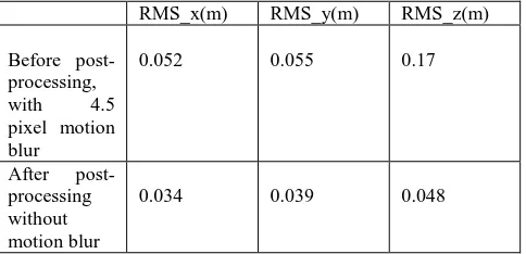
RMS_x(m) RMS_y(m) RMS_z(m)
Before post- processing,
with 4.5
pixel motion blur
0.052 0.055 0.17
After post- processing without motion blur
0.034 0.039 0.048
Table 1. AT residuals of the check points
Table.1 shows that the RMS of the horizontal points after motion compensation, when considering a 2 pixel error for measuring non-signalized control points, is improved and in an acceptable range. This improvement is more obvious in vertical points and shows that the linear blur compensation in absence of the angular motion blur, has a greater effect on the vertical accuracy. It is expected to achieve better absolute accuracies within 1 pixel for horizontal and 2 pixels for height by using signalized control points.
(a)
(b)
(c)
Figure 6. (a): shows the effect of temperature changes on the focal length which is approximately 0.01 mm per every 10 degrees temperature changes, i.e. 0.03mm for 30 degrees. (b) and (c) shows the effect of temperature changes on the principal point position(Xp,Yp). This is important when the camera is calibrated in the lab environment but is operated in a different temperature environment.
(a)
(c)
(e)
(g)
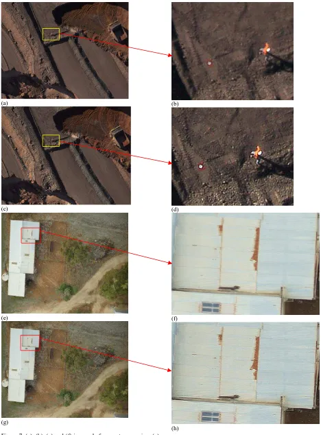
Figure 7. (a), (b) ,(e) and (f) images before post-processing, (c) (d), (g) and (h) after post-processing. More details are visible after post-processing.
(b)
(d)
(f)
(h)
4. CONCLUSION
We have shown that for photogrammetry at highest accuracy, it is very important to model and eliminate the sideways and forward motion of the UAV. This will improve the height accuracy up to five times and will have a considerable impact on the horizontal accuracies and stability of the models. Camera motion during image capture with CMOS sensors will cause random geometric distortions and image warping, as well as image blur. The distortions and warping depend on the focal plane direction of the shutter and flight direction by corrupting the interior orientation parameters which are a fundamental issue for any photogrammetric approach. We also showed that by applying the correct PSF to each image, more details will be retrieved (see Figure 7b and d). This method can be applied for any metric and non-metric cameras with CCD or CMOS sensors to eliminate the amount of blur and pixel distortions caused from unexpected movements of the fixed wing, rotary UAVs or other imaging platforms and will eliminate the possible need for a repeat flight. Post-processing of the UAV images for eliminating the motion blur distortions and applying the temperature based camera calibration parameters and radiometric corrections, will produce perfect images for the highest grade photogrammetric processing. For future developments we are considering a custom designed miniature image processing chip for on-board processing and real-time blur corrections.
REFERENCES
[1] M. Cannon, Blind deconvolution of spatially invariant image blur with phase, IEEE Trans. Acoust. Speech Signal Process. 24 (1) (1976) 58–63.
[2] Jong Min Lee, Jeong Ho Lee, Ki Tae Park, Young Shik Moon, Image deblurring based on the estimation of PSF parameters and the post-processing. Optic 2012.
[3] W.H. Richardson, Bayesian-based iterative method of image restoration, J. Opt.Soc. Am. 62 (1) (1972) 55–60
[4] http://en.wikipedia.org/wiki/Richardson-Lucy_deconvolution
[5] Photogrammetry: geometry from images and laser scans, 2nd edition By Karl Kraus University of Vienna Austria. pp. 155-157
[6] M. J. Smith , E. Cope, 2010. The effects of temperature variations on single-lens-reflex digital camera calibration parameters. International Archives of Photogrammetry, Remote Sensing and Spatial Information Sciences, Vol. XXXVIII, Part 5 Commission V Symposium, Newcastle upon Tyne, UK.
ACKNOWLEDGEMENTS
The author thanks A/Prof. Jorg M.Hacker for reviewing this paper.