PERFORMANCE ASSESSMENT AND GEOMETRIC CALIBRATION OF
RESOURCESAT-2
P.V.Radhadevi*, S.S.Solanki, A. Akilan, M.V Jyothi, V. Nagasubramanian
Advanced data Processing Research Institute, Dept. of Space, 203, Akbar Road, Manovikasnagar P.O.
Secunderabad 500 009, India
Commission I, WG I/3
KEY WORDS: On-orbit calibration, sensor model, inter-camera alignment, band to band registration
ABSTRACT:
Resourcesat-2 (RS-2) has successfully completed five years of operations in its orbit. This satellite has resolution and multi-spectral capabilities in a single platform. A continuous and autonomous co-registration, geo-location and radiometric calibration of image data from different sensors with widely varying view angles and resolution was one of the challenges of RS-2 data processing. On-orbit geometric performance of RS-2 sensors has been widely assessed and calibrated during the initial phase operations. Since then, as an ongoing activity, various geometric performance data are being generated periodically. This is performed with sites of dense ground control points (GCPs). These parameters are correlated to the direct geo-location accuracy of the RS-2 sensors and are monitored and validated to maintain the performance. This paper brings out the geometric accuracy assessment, calibration and validation done for about 500 datasets of RS-2. The objectives of this study are to ensure the best absolute and relative location accuracy of different cameras, location performance with payload steering and co-registration of multiple bands. This is done using a viewing geometry model, given ephemeris and attitude data, precise camera geometry and datum transformation. In the model, the forward and reverse transformations between the coordinate systems associated with the focal plane, payload, body, orbit and ground are rigorously and explicitly defined. System level tests using comparisons to ground check points have validated the operational geo-location accuracy performance and the stability of the calibration parameters.
1. INTRODUCTION
Resourcesat-2 (RS-2) ground segment is fully operational since on-orbit acceptance (October 2011). RS-2 is intended to continue the remote sensing data services to global users provided by IP6 (1) with enhanced performance. Important changes in RS-2 compared to RS-1 are: Enhancement of LISS-4(L4) multispectral swath from 23 km to 70 km and improved radiometric accuracy from 7 bits to 10 bits for LISS-3 (L3) and L4 and 10 bits to 12 bits for AWIFS (AWF). Besides, suitable changes, including miniaturisation in payload electronics, have been made in RS-2. The satellite is also equipped with gyros, star sensors and a positioning system SPS for getting a precise direct sensor orientation and position.
On-orbit calibration is a pre-requisite to guarantee the geometric quality of high-resolution optical satellite imagery for direct geo-referencing. The accuracy of the parameters computed is crucial for overlaying the data from multiple sensors, with existing datasets or maps and use them for evaluations like change detection, map updating etc. In recent years, a large amount of research has been devoted to the in-orbit calibration, geometric rectification and quality assessment methods towards the efficient utilization of high-resolution image data and full exploitation of the highly accurate ephemeris and attitude data from the GPS and star sensors on-board. On-Orbit geometric calibration model and its applications for high resolution optical satellite imagery is explained by Wang et.al, 2014. Location and mapping of the focal plane of Pleiades High Resolution system
* Corresponding author fax: - +91-040-27781217 E-mail address: - [email protected]
through in-flight geometrical calibration is done by Françoise de Lussy et.al, 2012. Sensor calibration method of three-line CCD scanners on ZY-3 is explained by Shenghui Fang and Yifu Chen, 2012. Pre-flight and in-flight geometric calibration of SPOT-5 HRG & HRS images is studied by Breton et al, 2002. Mulawa, 2004 explains a method for the on-orbit geometric calibration of the orbview-3 high resolution sensors. The in-flight calibration results of multiple cameras of IRS-P6 and calibration and orientation of ALOS/PRISM imagery with a generic sensor model are presented in Radhadevi et.al, 2008 and Radhadevi et.al, 2011 respectively.
Details of geometric calibration and quality assessment performed for RS-2 images are presented in this paper. The image quality commissioning of RS-2 was done in two phases. The first two months were dedicated for testing all different modes and image radiometry in order to ensure that RS-2 was fulfilling its specifications and ready for commercial exploitation. During the next four months, image quality commissioning went on, with a fine characterization and improvement of the first calibration process. Even after declaring the satellite operational, geometric analysis is continued for several months, allowing a characterization of the behavior of these biases over time and a modelling of orbital and seasonal variations that would impact location performance. Initial interior orientation parameters of RS-2 were determined by pre-launch lab measurements. Refining the pre-pre-launch sensor alignment knowledge is critical to ensure that geometric accuracy specification of system level product is met. These biases are The International Archives of the Photogrammetry, Remote Sensing and Spatial Information Sciences, Volume XLI-B1, 2016
included in the camera geometry to assess the absolute accuracy. An important aspect of this assessment is to help decide which parameters of the geometry of the camera most probably needed adjustment. A selection of a subset of parameters is recommended in order to avoid cross-correlation effects and increase redundancy and the overall robustness of least-squares estimation. In-flight calibration of multiple sensors of RS-2 is achieved by proceeding through a series of steps. They are (1) individual sensor alignment calibration (2) inter-camera alignment calibration and (3) focal plane calibration. The focal plane calibration includes effective focal length computation, band-to-band registration and alignment of staggered arrays. Each of these calibration methods are elaborated in forthcoming sections.
Mission specifications for band to band registration in MX is 0.25 pixels for L4 whose bands are placed parallel in the focal plane which will image the same feature on the ground with a time gap of 2.1 sec. Location accuracy specification is about 200m. After first phase of calibration performed during commissioning, the alignment offsets are computed and fixed with which both these specifications were met.
2. GEOMETRIC CALIBRATION
RS-2 satellite includes several sensor types such as: GPS receivers, star sensors, earth sensor, gyros and three cameras. In order to produce high quality metric imagery, the on-orbit data from all of these sensors need to be combined in a calibration process to produce the geometric model parameters of the sensor system. The calibration requires a reconstruction of the imaging process.
Bore-sight alignment angles and focal plane geometric parameters are part of the collinearity equations used in the sensor model. During in-flight calibration, these parameters are updated in a self-calibration approach. It can be applied to multiple cameras and payloads with little or no change to the bundle adjustment pattern. Another advantage of this approach is that it can consider systematic effects on the image coordinates from any sources and not only those which depend on the modelling of the optical geometry. Therefore, it is better to use the same sensor model for in-flight calibration as well as for operational product generation. But the disadvantage of this approach is that the parameters will be highly influenced by the distribution of GCPs. During the commissioning phase of the satellite, this method can be used for many test datasets with good distribution of control points to fix the camera parameters. Full sets of radial and tangential distortion parameters are difficult to address, because they correlate each other. Therefore, the appropriate parameters must be selected based on the analysis of their correlations and quality. It is important, that the treatment of the deformation parameters and the analysis of the correlations and accuracies are efficiently implemented in the software. Bore-sight alignment angles and the focal length are the main calibration parameters. Correlation between the physical parameters of the camera and the bore-sight parameters is very significant; for example, the focal length and the bore-sight angle in yaw direction (dκ) are correlated. If the distortion residual is apportioned into line and sample residuals, this coupling can be separately addressed. Effects of certain parameters cannot be measured explicitly. Instead, a resulting total effect will be measured and assigned only to the selected parameters. Therefore, the sensor model is analysed with different sets of parameters. Approach is similar to that is explained in Radhadevi et.al 2011.
3. AUTOMATIC IDENTIFICATION OF POINTS
Ground control points/check points are identified from aerial photographs, Carto-1 ortho images or public domain ortho tiles like ETM. Heights are extracted from aerial DEM, Carto-1 DEM, ASTER or SRTM. Powerful image correlation methods are used to help reduce the cost and time needed to measure the control points in the aerial and satellite imagery. An advantage of automatic identification of GCPs/check points from reference images is that a large number of distributed points can be used for the characterization and calibration of the camera.
4. ATTITUDE ANALYSIS
Satellite position and orientation are given in Ancillary Data Information File at every 40 msec. Attitude data in terms of quaternion are converted into Euler angles. For predicting position and attitude parameters at desired times from the given telemetry data, a polynomial curve fit is made. The initial values of all the parameters are derived by least squares adjustment to the ephemeris data using a generalized polynomial model. During April-May 2012, a problem in the attitude behavior was noticed for few datasets and reported to the AOCS team. Such datasets were failing to meet the specifications of location accuracy as well as band to band registration (BBR) for Liss-4. First exercise done was to plot the attitudes of different datasets. Sub-scenes are chosen for the study. Figure-1 shows roll and pitch angles at the image start time for about 300 datasets. Each dot in the figure shows a data set. It is clear from these figures that roll and pitch values of few datasets in April-May 2012 (orbit 4300 to 5300 approximately) are overshooting. These datasets show different roll and pitch profiles/values compared to other datasets. A temporary solution was developed to handle such data sets in data products generation chain. It is based on the methodology of reconstructing the platform attitude through GCPs. Many products which were failing could be regenerated through this method. Figure 2 shows the impact of this attitude problem in BBR. Left figure shows a small area from a product generated with given attitude and right figure shows the product generated with the temporary solution.
.Figure 1 Roll and Pitch angles at image start (each point represents a dataset)
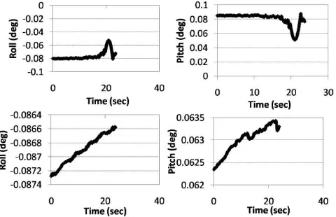
Roll and Pitch profiles of one such problematic data (orbit 4874) is compared with another data (orbit 2785) with normal attitude behavior in figure 3. It can be seen that the variation in roll and pitch values within a sub scene is much higher for Orbit 4874 compared to that for Orbit 2785. Also, a sudden kink in the The International Archives of the Photogrammetry, Remote Sensing and Spatial Information Sciences, Volume XLI-B1, 2016
profile was also noticed. This was identified as a small problem in the gyro rate integration and smoothening. Later, the attitude restitution program was modified by the AOCS and re-installed at the ground station. Subsequently, an improvement in the in-flight calibrated parameters as well as BBR refinement algorithm for Value Added products Generation is done. Using this updated s/w, a campaign mode exercise was carried out for re-generation of BBR-failed datasets, and almost all the earlier-rejected products were cleared. For this purpose, performance assessment of RS-2 and geometric accuracy analysis was done rigorously for images form Liss-3, Liss-4 and AWiFS over different types of terrain and viewing angles (for Liss-4).
Figure 2 Band to band mis-registration in the L4 product due to an error in the attitude restitution (left) and product after reconstructing the platform attitude with GCPs (right)
Figure 3 Rolland Pitch profiles of Orbit 4874 (above) and orbit 2785 (below)
5. INDIVIDUAL SENSOR ALIGNMENTCALIBRATION
Individual sensor alignment calibration deals with the orientation of each sensor with respect to the attitude frame. This includes the determination of the attitude relation and shifts between the coordinate system of star sensor, body and the imaging sensor along with the interior orientation of the sensor. Computation of bore sight misalignment angles is a difficult task. Each CCD of a sensor in the focal plane has an orientation with respect to the payload and each payload has an orientation with respect to the body. The body frame has an orientation with respect to the inertial frame. The primary challenge in alignment calibration is the need to estimate the underlying alignment trend for each sensor from a series of precision correction solutions, which measure a combination of orbit, attitude and alignment
errors. The following criteria are followed to decide the alignment trend for each sensor.
(a) If each of the three payloads shows the errors of the same order over the same ground area, then the bias is in the attitude determination.
(b) If errors are consistent over different images (with different viewing configurations) of the same sensor, but vary from sensor to sensor, the error can be due to a combination of payload to body residuals of different sensors and attitude determination. (c) If the errors of a particular ground area are not consistent over different images of the same payload (L4 on different viewing configurations), the errors can be due to payload steering. Within an image, distortion is divided into two separate directions: line and sample residuals. The distortion in the line direction is primarily due to radial distortion of the optical system and a yaw of the detector with respect to payload cube normal.The distortion in the sample direction can be thought of as scale distortions along the arrays which can be due to small variation in focal length.
To show apparent distortions at the focal plane, an adjustment solving for only the focal length and camera alignment parameters was performed. The resulting image residuals show the remaining optical and focal plane distortions. Errors affecting the geo-rectification and co-registration accuracy can be categorized into three groups, viz., static pointing errors, dynamic pointing errors and errors associated with the topography of the projection surface. The topography errors can be accounted by including a digital elevation model during the geo-rectification. In-flight calibration is designed to take into account static pointing errors. The model consists of a set of parameters used in a mathematical expression that gives the pointing direction of an arbitrary pixel to the spacecraft attitude frame of reference. These parameters account for distortions from an ideal optical system. The errors due to slight variations in these parameters are static in nature. Thus, exterior orientation can be used for a verification of the calibration and a check of the quality of the direct sensor orientation. In order to deal with dynamic errors due to high oblique viewing and the satellite attitude variations during the pass, a differential correction of the orbit and attitude parameters with the help of GCPs are to be incorporated into the adjustment model.
An extensive analysis with different datasets reveals the behaviour of each sensor. Modelling error, that is the inability of the model to reconstruct the viewing geometry, also will reflect as an error at the checkpoints after precision correction. Similar is the case with point identification errors. Therefore, using a correct mathematical model as well as precise GCPs/check points is very important for in-flight calibration. The bore sight misalignment is computed by comparing the attitude parameters determined by the navigation system with the parameters after correcting with GCPs. Band 3 of L4 camera with vertical viewing configuration is taken as primary sensor for which the focal length and angular placements of the first and last detectors are taken unaltered. Vertical viewing image is preferred to compute individual sensor alignment biases because the disturbances introduced over these biases due to Payload steering (for oblique viewing) should be analysed separately. Few distributed GCPs and checkpoints are identified automatically in the images. Initially, we assigned zero value to the payload alignment biases in the rotation matrix of the sensor model. Then, ground co-ordinates are computed for the checkpoints using the sensor model and the given GPS/INS (Inertial Navigation System) orientation parameters. Difference between the derived ground co-ordinates and the actual co-ordinates are analysed. The error vectors from many images showed the same trend. Location accuracies of L4 without incorporating the alignment angles are The International Archives of the Photogrammetry, Remote Sensing and Spatial Information Sciences, Volume XLI-B1, 2016
(average from different datasets) 673m in latitude direction and -1616 m in longitude direction. Average accuracies from different data sets of L3 are -290 m in latitude direction and -306 m in longitude direction where as that of AWF are -1143 m in latitude direction and 366 m in longitude direction.
Now, the sensor orientation parameters are updated with the rigorous sensor model and GCPs. The difference in exterior orientation parameters before and after correction are computed for all the data sets and compared. These biases will account for offsets between body frame and payload, small variations in the interior orientation of the sensor and focal plane geometry, alignment offsets between inertial frame and body frame and uncertainty in the given orbit and attitude parameters. We cannot really apportion each of them. But, the common bias (trend) from the images (of a sensor) should be taken out as the offset of the payload and this will account for the first two offsets mentioned above. After the correction of the attitude problem, no more variation of the performance has been observed and absolute system location performance of L4 without using any GCP is brought within 100 m.
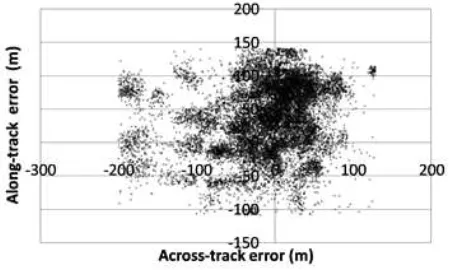
Figure 4 Absolute location performance of L4 (a) before correction and (b) after correction
Figure 5 Absolute location performance of L4 (Band3) with system knowledge after alignment angle correction (16244 Points from different datasets)
Figure 4 shows the planimetric error at a set of checkpoints over a nadir-looking image of L4. Each point in the figure show the root mean square error (RMS) (with sign of mean) computed from a dataset. Geo-location performance evaluated for 16422 points from 260 datasets after correction is shown in figure 5. It is clear from this figure that system level accuracy specification is met. After incorporating the biases, the errors from different datasets vary mostly within +/- 100 m. A small shift (from zero mean) especially in across-track error (see figure 5) for few datasets is due to payload tilt, seasonal stability, on board thermal
control and clock synchronization error. This error can be corrected with the help of GCPs during precision products generation. The exercise is done for band 3 of L3 and AWF also to compute the sensor alignment offsets. About 150 datasets are analyzed for L3 and 60 datasets for AWF (A&B). Figures 6 and 7 shows the absolute location performance of L3 and AWF. Individual sensor alignment calibration will ensure that the location performances of all the images are within the system level accuracy specifications.
Figure 6 Absolute location performance of L3 after correction
Figure 7 Absolute location performance of AWF after correction
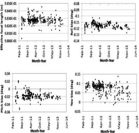
Figure 8 shows the calibration parameters computed for 345 datasets of L4. Average effective focal length computed is 0.9827 m which indicates that there is a variation of about 0.3 mm from the pre-launch calibrated focal length for band 3 of L4. Average Roll bias computed is -0.115 0. Seasonal variations can also be
noticed as a small trend in the roll bias. Pitch and Yaw residuals show a spread across different datasets. Still a systematic component of about -0.020 in pitch and 0.08 0 in yaw can be taken
as a bias. The reason for the spread in residual pitch for L4 was identified due to the Payload steering mechanism. This phenomenon will be analyzed in the next section. Figure 9 shows the in-flight calibration parameters computed for L3. During the ground segment operationalization of the satellite, many datasets were used for computation of alignment angles. L3 camera is fixed and nadir looking which will not be tilted during image acquisition. The calibration parameters also show this steady behavior and have not changed even after 3 years. Figures 10 and 11 shows the calibration parameters computed for AWF-A and AWF-B.
Figure 8 Payload alignment angles and Effective focal length computed for L4 datasets
Figure 9 Payload alignment angles and Effective focal length computed for L3 datasets
Figure 10 Payload alignment angles and Effective focal length computed for AWF-A datasets
Figure 11 Payload alignment angles and Effective focal length computed for AWF-B datasets
6. PAYLOAD STEERING ALIGNMENT CALIBRATION OF L4
The behavior of the payload steering is analyzed and measured using payload steering alignment calibration. L4 camera is capable of imaging with view angles up to +/-260 with payload
steering mechanism. When payload is tilted, the bias angles between the payload and attitude co-ordinate system can get disturbed. Also, small magnitudes of rotation angles (unintentional) can be introduced in other directions. To study this behavior, many images with different look angles (from different orbits) are analyzed. Error due to the combined effect of terrain topography and the look angle will be mainly in the across-track direction. Inclusion of a global digital elevation model during geo-rectification can minimize this. The process compares the terrain corrected image to a high accuracy reference image to detect systematic deviations of the payload steering motion from its nominal pre-launch profiles for forward and reverse payload steering. After individual sensor alignment calibration, errors were brought within 100m for nadir viewing images of L4. But when analyzed further, it was noticed that latitude errors for negative tilts show around -100 m (RMS with sign of average) where as positive tilts show positive error. This indicates that there is a trend when the payload steering mechanism is on. That means as a function of look angle, a small pitch is introduced. The measured deviations are analyzed as a function of look angle. Thus, an additional Pitch bias as a function of tilt angle is included in data products generation function.
7. INTER-CAMERA ALIGNMENT CALIBRATION
Inter-camera alignment is done to ensure same relative location accuracy from all sensors. Approximate alignment offsets of all sensors with respect to body frame are achieved from individual sensor calibration using checkpoints. To check the relative location performance, identification of same points in L4, L3 and in AWF is practically very difficult as they are of very different resolutions. Band 3 of L4 nadir looking image after fixing the residuals is taken as the primary sensor and other sensors are oriented relatively with respect to this primary sensor. Any fixed ground extent covering clear-cut and long features (for example, rail or road network) in L4 is georeferenced (without GCPs) and written in the resolution of L3 with a global DEM included in the rectification. For the same ground extent, georeferenced products are generated from L3 and AWF in the same resolution with a The International Archives of the Photogrammetry, Remote Sensing and Spatial Information Sciences, Volume XLI-B1, 2016
DEM. Including a DEM while generating the products is very important to ensure that the computation of the sensor alignments are not influenced with terrain topography. Various sensors are having different look angles and resolutions. Therefore, the effect of terrain relief on different images will be different. Superimposition of the products and comparison will give relative alignment offsets, which can be corrected by fine-tuning the biases of L3 and AWF with respect to body axes. These parameters will not change for different orbits as L3 and AWF (AWF-A and AWF-B) cameras are not tiltable. Once the relative calibration is considered as reliable, remaining location errors are shared by all cameras and are due to the uncertainty in the given attitude. A block adjustment with tie points identified between the sensors also was used to ensure the relative location performance.
8. FOCAL PLANE CALIBRATION
Focal plane calibration includes the alignment of different bands in multispectral imagery, computation of effective focal length and the alignment of odd and even detectors within each CCD array.
8.1 Effective Focal Length Computation
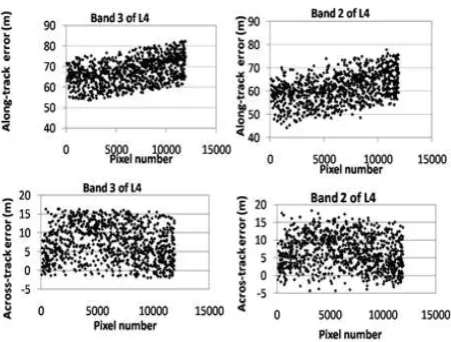
As explained in section 5, effective focal length computation is done for band 3 of all cameras (figures 8, 9, 10, 11). Alignment offsets and EFL of band 3 of all cameras, computed through individual sensor alignment calibration and payload steering calibration, are fixed. Effective focal lengths and alignment offsets of other bands are computed relatively with respect to band 3. As there is a time gap of 2.1 seconds between the extreme bands of L4, relative attitude errors need to be solved to improve the internal accuracy of L4 images. Internal accuracy of the images can be guaranteed using a concept called “relative GCPs”. Based on this principle, the location of a ground object obtained by forward projection of a point in band 3 is computed. Corresponding image coordinates in band 2 and band4 are obtained by image matching. Image coordinates of band 2 along with object coordinates obtained from band 3 are used as GCPs (relative) for solving calibration parameters of band 2. Actually we are computing the relative attitude pattern by imposing a constraint that if corresponding points in all the bands should see the same location on the ground, what should have been the deviation in attitude over and above the given attitude profile. This is repeated for many datasets and analyzed to know whether a systematic component is present in the attitude behavior between the bands. Figure 12 shows the along-track as well as across-track errors at a set of conjugate points between band 2 and band3. EFL and alignment angles computed for band 3 are used for band2 also. X axis shows the pixel location. Along-track and across-track errors of band3 do not show any trend along the detector array where as they clearly show a trend for band 2. If the plot with pixel versus residual in line direction shows a trend, the reason could be due to a change in yaw. If the plot with pixel versus residual in pixel direction shows a trend, the reason could be due to a change in EFL. From figure 12, it is clear that yaw alignment and EFL of band 2 are to be fine-tuned with respect to that of band3. Apart from that, roll and pitch biases are also different because errors are showing a different magnitude range from that of band 3. Thus, using the concept of “relative GCPs”, parameters of band2 and band4 are recomputed.
Effective focal lengths are computed by comparing the longitude error (RMS) of a set of checkpoints. The object co-ordinates of measured image points have been intersected based on system level position and attitude data provided, improved by the bore-sight misalignment. This is repeated with slightly different focal
lengths. The process terminates at focal length resulting lowest longitude error. Band 4 does not show any change in the focal length from the pre-flight calibrated value whereas band 2 shows an effective focal length difference of about -0•3mm from the pre-launch value to give the absolute location performance (also same relative location performance with band 3).Figure 13 shows that after the correction, different bands of L4 perform same location performance
Figure 12 Along-track and across-track errors of band 3 and band2 before correcting the parameters of band 2
Figure 13 Along-track and across-track errors of band 3 and band2 after correcting
8.2 Band to Band Registration (BBR)
Same line on the ground will be imaged by extreme bands of L4 with a time interval of 2.1 s. In other words, there exists a time difference between the observation moments of each linear sensor’s scanning in along-track direction. During which the satellite would have moved through a distance of about 14 km on the ground and the earth also would have rotated through an angle of 30 arc s. The multi-spectral bands are separated with an angular separation of 0.9630 between leading and following
bands. During the interval of observation time, some exterior orientation elements of the camera might have small changes due to attitude jitter, and thus the same ground object might be imaged at slightly different locations on the two images. This cannot be corrected fully with the given attitude information at The International Archives of the Photogrammetry, Remote Sensing and Spatial Information Sciences, Volume XLI-B1, 2016
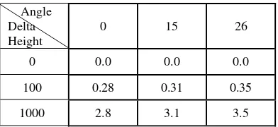
40 msec. To ensure perfect BBR, we have to account for Orbit and attitude fluctuations, terrain topography, Payload Steering Mechanism (PSM) and variations in the angular placement of the CCD lines (from the pre-launch values) in the focal plane. Band to band registration (BBR) or co-registration is a requirement for multispectral (Mx) imagery of RS2. L4 extreme detectors are imaging with time gap of 1.2 and 0.9 sec with respect to middle band, this when combined with view direction and terrain will introduce band to band mis-registration. Table 1 shows the mis-registration error between the bands with different look angles in combination with terrain height error.
Table 1 Band to Band mis-registration (in pixels) in L4MX with different PSM steering angles and height uncertainty
Angle information or through geometry-based method where proper knowledge of payload geometry and orbit and attitude information is the primary requirement. Since BBR correction is required for every image and total image-based approach highly depends on image content, it has got some limitation. To overcome this, we developed an automated hybrid approach where in-flight calibration tuned photogrammetric process utilizes given attitude information and acquisition geometry to correct band to band mis-registration to a large extent and image is used to derive residual attitude to correct residual mis-registration between the bands. As image is continuous observation and has higher sampling rate compared to measurement system on board, it is appropriate to use it along with geometric information to strengthen the BBR correction performance. A method is adopted to Detect and Correct the Relative Attitude Errors between the bands using parallel observations which will ensure perfect band to band registration. Parallax disparities after the correction can be brought to +/-0.3 pixel with the relative attitude correction method. Brief steps for automated BBR - hybrid approach are
• Precise In-flight camera calibration
• Orbit attitude modeling (OA modelling without GCP’s)
• Matching between band 3 with band 2 and 4 respectively over defined grid. We fix three columns in start, middle and end of swath direction and perform similarity measure operation based on mutual information technique to identify match at regular interval between extreme and middle band in pair
• Extraction of height from a global DEM at the ground coordinates for matched point
• Apply blunder point removable based on OA model, and retain point within specified threshold.
• Use every matched point in band 2 and 4 respectively as GCP and compute residual attitude correction for roll and pitch required with respect to given attitude.
• Fit 3rd order polynomial between time and computed
residual attitude correction for roll and pitch.
• Construct grid over band 2 and 4 using OA model with residual attitude corrections.
• Re-write band 2 and 4 by applying grid based re-sampling. Keep band 3 untouched.
The resulted product will be orbit- aligned product with optimal BBR correction and ready for further photogrammetric operation as middle band geometry is untouched. This whole process is atomized. Residual attitude correction-based method was done in normal phase operations and it was observed that this procedure restricts BBR within specification of 0.2-0.3 pixel without any manual interaction.
(a) (b) (c) Figure 14. Band to band registration (a) original image (b) corrected with given attitude information (c) corrected with residual attitude computed over and above the given attitude
Figure 15. Band to band registration (before and after residual attitude correction)
9. CONCLUSION
Performance assessment and in-flight calibration for the satellite RS-2, carrying multiple cameras with widely varying look angles and resolutions, is realized with the inclusion of a rigorous sensor model, metadata information about the position and attitude of the satellite, precise camera geometry and datum transformation. All the objectives of carrying out the in-flight calibration are met with the outputs of the present study. We have developed and implemented a method for automatic co-registration of multiple bands of L4 camera using photogrammetric means and complementing it with an image-based matching technique to remove unaccounted mis-registration residuals using the first method. System level tests using comparisons to ground check points have validated the operational geo-location accuracy performance. The imagery was collected over a period of three years and this demonstrates the stability of the calibration parameters. 90% of the datasets have a system level location accuracy within +/-100m RMS for all the sensors. Location accuracy of less than a pixel could be achieved for all the sensors with GCPs. In order to do performance assessment and geometric calibration exercise it was required to have consistent identification of GCPs with available references and conjugate points between pair of images, that to in large number. This was achieved with in-house developed robust automatic point identification techniques.
The calibration results are included for operational use with which the data processing is significantly simplified. This has enabled to achieve mission specification with respect to location accuracy for all sensors and band to band registration within +/- 0.3 pixels for Liss-4. The results are representative of the stability of the platform and show the potential of RS-2 for accurate georeferencing.
ACKNOWLEDGEMENTS
The authors gratefully acknowledge Shri. Santanu Chowdhury Director, ADRIN for his encouragement and support for this work.
REFERENCES
Breton, E., Bouillion, A., Gachet, R. , Delussy, F. , 2002. Pre-flight and in-Pre-flight Geometric calibration of SPOT-5 HRG and HRS images, Pecora 15/Land Satellite Information IV/ISPRS Commission I/FIEOS 2002 Conference Proceedings
Françoise De Lussy, Daniel Greslou, Cécile Dechoz, Virginie. Amberg, Jean Marc Delvit, Laurent Lebegue, Gwendoline Blanchet, Sebastien FouresT, 2012. Pleiades HR in-flight geometrical calibration: location and mapping of the focal plane, International Archives of the Photogrammetry, Remote Sensing and Spatial Information Sciences, Volume XXXIX-B1, 2012, 519-523
Mulawa, D., 2004. On-orbit geometric calibration of the orbview-3, high resolution imaging satellite. International Archives of Photogrammetry, Remote Sensing and Spatial Information Sciences, 35(B1), 1-6.
Radhadevi, P. V., Solanki, S. S., 2008. In-flight calibration of multiple camera of IRS-P6. Photogrammetric Record 23(121), 69-89.
Radhadevi, P. V., Rupert Müller, Pablo d‘Angelo, Peter Reinartz, February 2011. In-flight Geometric Calibration and Orientation of ALOS/PRISM Imagery with a Generic Sensor Model. Photogrammetric Engineering & Remote Sensing, Vol. 77, No. 2.
Shenghui Fang, Yifu Chen, 2012. Sensor calibration of three-line CCD Scanners of ZY-3. International Archives of Photogrammetry, Remote Sensing and Spatial Information Sciences, Vol. XXXIX-B1.109-114
Wang, M., Yang, B., Hu, F., Zang, X., 2014. On orbit geometric calibration model and its application for high resolution optical satellite imagery, Remote Sensing 2014, 6(5), 4391-4408; doi:10.3390/rs6054391