USE OF VERTICAL AERIAL IMAGES FOR SEMI-OBLIQUE MAPPING
D. Poli a, K. Moe a, K. Legat b , I. Toschi b, F. Lago b, F. Remondino b
a Terra Messflug GmbH, Eichenweg 42, 6460 Imst, Austria – (k.moe, d.poli)@terra-messflug.at b Vermessung AVT-ZT-GmbH, Eichenweg 42, 6460 Austria – [email protected]
c 3D Optical Metrology (3DOM) unit, Bruno Kessler Foundation (FBK), Trento, Italy – (toschi, lago, remondino)@fbk.eu
Commission I / WG2
KEY WORDS: Aerial photogrammetry, Oblique camera, Modelling, Mapping
ABSTRACT: The paper proposes a methodology for the use of the oblique sections of images from large-format photogrammetric cameras, by exploiting the effect of the central perspective geometry in the lateral parts of the nadir images (“semi-oblique” images). The point of origin of the investigation was the execution of a photogrammetric flight over Norcia (Italy), which was seriously damaged after the earthquake of 30/10/2016. Contrary to the original plan of oblique acquisitions, the flight was executed on 15/11/2017 using an UltraCam Eagle camera with focal length 80 mm, and combining two flight plans, rotated by 90º (“crisscross” flight). The images (GSD 5 cm) were used to extract a 2.5D DSM cloud, sampled to a XY-grid size of 2 GSD, a 3D point clouds with a mean spatial resolution of 1 GSD and a 3D mesh model at a resolution of 10 cm of the historic centre of Norcia for a quantitative assessment of the damages. From the acquired nadir images the “semi-oblique” images (forward, backward, left and right views) could be extracted and processed in a modified version of GEOBLY software for measurements and restitution purposes. The potential of such semi-oblique image acquisitions from nadir-view cameras is hereafter shown and commented.
1. INTRODUCTION
One recent innovation in aerial photogrammetry is the development of commercial metric optical cameras for the acquisition of oblique images (e.g. UltraCam Osprey series by Vexcel Imaging, Urban Mapper by IGI, MIDAS by Track`Air or RCD30 by Leica) and their rigorous photogrammetric processing (Remondino et al., 2016; Remondino and Gerke, 2015). The Austrian company Vermessung AVT-ZT-GmbH (later AVT) with subsidiary Terra Messflug GmbH has been operating oblique aerial flights with UltraCam Osprey cameras for cartographic mapping since 2015. After rigorous investigations on the geometric properties of the oblique cameras and their potentials for mapping applications, AVT, in cooperation with the research institute Bruno Kessler Foundation (FBK) in Trento (Italy), has implemented the GEOBLY software for inventory survey and topographic mapping using oblique imagery (Moe et al., 2016). The software functionality includes data visualization (simultaneous co-located visualization of nadir and oblique images, image selection, view rotation, navigation pane) and mapping (point measurement in monoplotting and multi-image mode, 3D vector import, editing and export, layer management). The investigations on Imst test site (Austria) in 2015 and Bergamo (Italy) in 2016 confirmed earlier findings that the inclusion of oblique images to the nadir image block improves the accuracy of the aerial triangulation mainly in the vertical (Rupnik et al., 2015, 2014) and, thanks to the additional viewing directions, allows to generate dense 3D point clouds to reconstruct buildings façades or other features generally not visible in the nadir views (Moe et al., 2016).
Beside the investigations on oblique aerial cameras, AVT focused on the possibility to exploit the lateral parts of nadir images (“semi-oblique”), where, due to the perspective geometry, building façades or other vertical objects are visible by an oblique viewing direction. In other words, the challenge commissioned by the energy supplier company Engie SpA with the aim to provide the local administration with a measurement tool for building damage assessment. Section 3 reports about the data acquisition, while Section 4 discusses the aerial triangulation and image quality, while Section 5 presents the potential of the proposed acquisition geometry to 3D pointing accuracy in multi-ray forward intersection, with examples of application of the aerial survey for building damage assessment (i.e. linear measurements, volume estimation, 3D change analysis). Additionally, a software solution for image visualization and 3D vector digitalization from oblique imagery was adapted for usage with the semi-oblique images as described in Section 6.
To authors’ knowledge no other investigations and applications employed a crisscross flight with the later parts of nadir images for mapping purposes as in multi-view oblique cameras.
2. ACQUISITION GEOMETRY
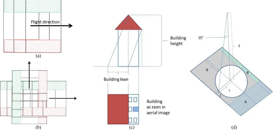
The aim of the research is to reach a “fake” five-view configuration (nadir, forward, backward, right, left) using only one nadir camera, instead of a Maltese-cross camera design. The optical sensor under consideration is the UltraCam Eagle Mark 1 (M1) (Vexcel Imaging, 2017) with focal length 80 mm and pixel size 5,2 m. Given the image size of 20010 x 13080 pixels, with the larger size perpendicular to the flight direction, the lateral parts of the image width can be used as side-looking semi-oblique views (2). Therefore, a crisscross flight plan composed by two blocks, rotated by 90°, could provide the desired four pseudo-oblique views. The first block, for example in East-West direction, will provide the “left” and “right” views and the second one, flown North – South, the “backward” and “forward” views, thus resulting in perpendicular strips (Figure 1a).
The approach is based on utilising the increased lateral “leaning
restitution, the focal length of the camera, as well as the desired minimal leaning angle must be considered. For this project, we aimed at a minimal building lean of about 14° or 25%. Thus, the top of a 10 m high object is shifted 2.5 m towards the image boundary due to the central-perspective projection. The radius of the “unusable” inner part of the image is given by r = f * minimal lean (%). For the current camera (80 mm focal length), the radius is 20 mm in the image plane. As the Eagle
M1 has an image size of 104 mm across and 64 mm along track, the remaining lateral section “q” corresponds to 32 mm on each side and an along-track section “l” of 14 mm (Figure 1c). For further use in the modified GEOBLY tool, only the q-part was considered, marked as image part “A” in Figure 1d.
(a)
(b) (c) (d)
Figure 1. a) Image acquisition for the generation of semi-oblique images (red and green parts). b) Combined plans for nadir and 4 oblique views acquisition. c) Representation of building leaning effect. d) The part of the image (A) used for the semi-oblique views, as a function of the focal length (f) and desired minimal leaning angle.
3. DATA ACQUISITION
The proposed approach was successfully tested on a photo flight over Norcia (Italy). The town, located in the Province of Perugia in the central part of Italy, is a historically distinguished village with landmarks from roman and middle age periods. After the earthquake on 30/10/2016 (Figure 1), AVT executed an aerial flight for the energy supplier Engie SpA, with the objective to acquire aerial images from five different viewing angles and to generate a 3D model of two priority areas (i.e. historic centres of Norcia and Castelluccio di Norcia), heavily damaged by the earthquake, in form of a dense 3D point cloud. Due to the low sun incidence angle in November, the flight had to be executed around noon with maximal duration of three
hours. The flight was planned with mean ground-sampling distance (GSD) of 5 cm and image overlap of 80% along flight direction and 60% between strips in the complete project area. For the historic parts in Norcia and Castelluccio di Norcia where a five-view acquisition was requested, two additional blocks were planned, with perpendicular flight direction compared to the main plan (Figure 3). The flight was successfully executed on 15/11/2016 under favourable weather conditions by an Italian partner company.
The sun inclination angle was quite low for a photogrammetric flight (25º to 28º), and caused long shadows, complicating the processing in the narrow historic parts of the villages. Therefore the image radiometry was improved locally by setting the correction parameters manually to lighten the dark areas.
Figure 2. View on Norcia before the earthquake (left) and examples of damages caused by the earthquake on 30/10/2017 (source: web).
Figure 3. Flight plan of Norcia project. Left: overall plan, including Norcia and Castelluccio di Norcia. Right: detailed plans for Norcia historic information (Ground Control Points – GCPs and Check Points – CPs) extracted from cadastre databases at scales 1:5.000 (Norcia) and 1:500 (Castelluccio). Therefore, the GCPs were used with a low weight within the AT. The bundle adjustment was run with the objective to achieve a very good relative orientation, which is an indispensable condition for 3D modelling and quantitative damage assessment. The statistical results of the Norcia’s and Castelluccio’s ATs are summarized in Table 1.
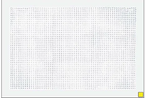
The high quality of relative orientation is demonstrated by the low re-projection errors of the tie points and the low residuals of the direct-georeferencing data. The numerical results of the exterior orientation are affected by the low accuracy, and thus 300 x 300 pixels, as calculated during the AT of the Norcia sub-block in Match-AT. The residuals shape is “typical” for the large-format UltraCam sensors, where residual patterns of the nine stitched sub-images (Wiechert and Gruber, 2015) can be recognized. The average length of the residual vectors in this
low local tie-point density. In other Eagle projects captured by AVT/Terra Messflug with the 100 mm lens system, the residuals are generally lower with values averaging around 0.14 pixels and a maximum of about 1 pixel. It is not completely clear if the difference is due to the different focal lengths of the two cameras or due to the time since latest camera calibration was performed. The camera used for Norcia was indeed calibrated 2.5 years prior to data capture with an estimated image residual error of 0.18 pixels; the two latest calibrations of our own sensor (Eagle Mark 1 f100 in 2015, and – after upgrade to the Mark 2 f100 – in 2016) yielded average residuals of 0.20 pixels and 0.12 pixels, respectively.
In any case, the residual error – although slightly stronger towards the image boundaries – is generally better than 0.2 pixels and, thus, well within the measurement accuracy. Therefore we neglect it in the successive image processing.
Figure 4. Residual images vectors for the used Eagle Mark 1 with produce the following geospatial products of both historic centres: (i) a 2.5D DSM cloud, sampled to a XY-grid size of 2 GSD, (ii) a 3D point clouds with a mean spatial resolution of 1 GSD (Figure 8) and (iii) a 3D mesh model at a resolution of 10 cm (Figure 6). Finally a traditional DTM-based orthophoto with
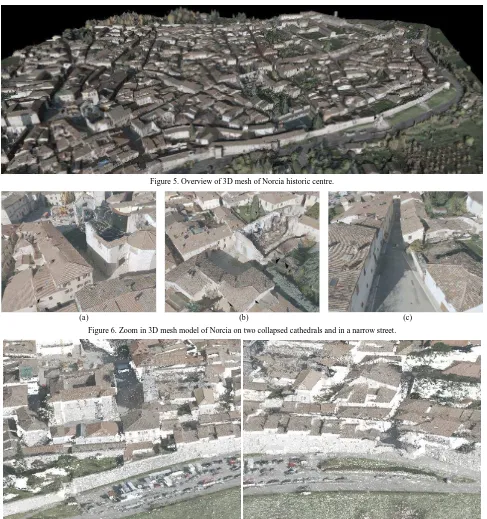
Figure 5 and Figure 6(a and b) show an overview of the 3D mesh of Norcia historic centre, with zoom in some damaged areas. The interpolated 3D surface model of the damaged areas allows the identification of the shapes of the buildings, the collapsed parts and the ruins on the ground in detail. Thanks to the two perpendicular flights over the historic area, even narrow alleys were clearly visible in the images and could be modelled (Figure 6c). The analysis of the point clouds (Figure 7 and
Figure 8) confirms the level of detail reached in the models. Given the high resolution of the 3D products, a quantitative assessment of the damages is also possible, through measurements of distances, areas and volumes in the point clouds. Examples of distance and area measurements are shown in Figure 7b. The height profile in Figure 9 gives information on the size of the standing walls and the ruins on the ground.
Figure 5. Overview of 3D mesh of Norcia historic centre.
(a) (b) (c)
Figure 6. Zoom in 3D mesh model of Norcia on two collapsed cathedrals and in a narrow street.
Figure 7. 3D point cloud of Norcia with RGB information.
(a) (b) Figure 8. Shaded 3D point cloud of Norcia with RGB information
Figure 9. 3D point cloud of damaged buildings in Norcia and height profile along a section.
6. MAPPING SOLUTION
One major challenge for the exploitation of the oblique parts of nadir images was the availability of a software solution for image visualization and 3D vector digitalization through
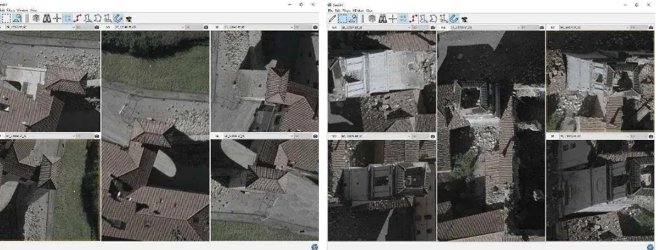
multi-view measurement. The GEOBLY software, originally designed for Maltese-cross cameras (Moe et al. 2016), was extended to the semi-oblique scenario of nadir-looking aerial cameras. In this mode, the outer parts of the images (according to a percentage threshold that can be freely chosen by the user) are cropped, and the corresponding oblique viewing directions (forward, backward, right or left) are assigned automatically. In case of Norcia, the percentage used to crop the images was 30% from the image boundary. The measurement functionalities in GEOBLY are the same as in the original version of the software designed for Maltese-cross cameras, i.e. data visualization (simultaneous co-located visualization of nadir and oblique images, image selection, view rotation, navigation pane) and mapping (point measurement in monoplotting and multi-image mode, 3D vector import, editing and export, layer management). The proposed acquisition methodology allows for multi-view mapping, with the possibility to investigate a target object from five different viewing angles (Figure 10), measure distances and areas and collect 3D vectors (Figure 11).
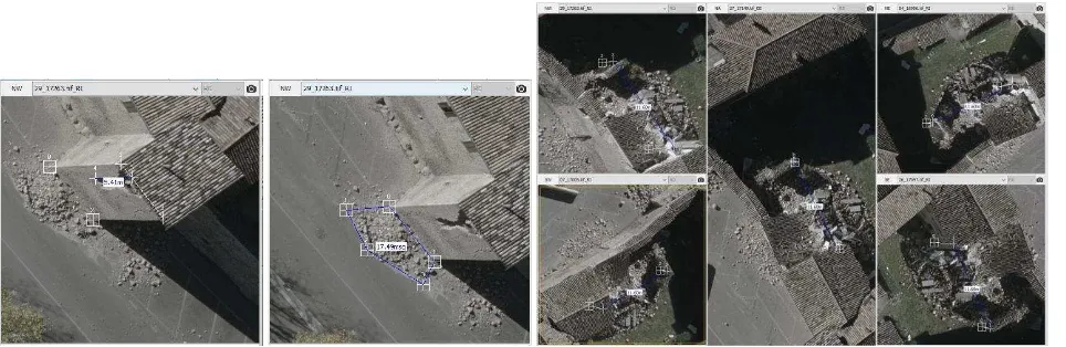
Figure 10. Visualization of two details from the Norcia nadir flight in semi-oblique mode within GEOBLY.
Figure 11. Examples of distance and area measurements in semi-oblique images within GEOBLY. geometric quality of the semi-oblique images, and the design of suitable flight planning schemes. It was decided to combine two flights with perpendicular flight directions and to extract the semi-oblique views (forward, backward, left and right) by cropping the lateral parts of the nadir images. In addition, the software GEOBLY, originally designed for Maltese-cross cameras, was adapted to visualize the semi-oblique images automatically and to perform measurements for mapping purposes.
The results presented in the paper have shown that semi-oblique mapping can be performed successfully and that surface modelling by dense image matching can potentially be used for damage detection and volume analysis. 3D data allow administrators to directly measure distances and areas in the damaged sections and to estimate volume of ruins and rubble material or volume changes. The project has validated a methodology that will be used as an attractive alternative by AVT/Terra Messflug for the acquisition of oblique imagery. While the Maltese-cross cameras provide better view of the façades, the semi-oblique approach provides a greater efficiency in flying – at least if oblique views are only necessary for parts of the area of interest.
ACKNOWLEDGEMENTS
The aerial data acquisition and processing were funded by Engie SpA who authorized the publication of the results. The implementation of GEOBLY software was partially funded by the Province of Tyrol (Austria) through the “Tiroler Innovationsförderung” scientific program.
REFERENCES
Moe, K., Toschi, I., Poli, D., Lago, F., Schreiner, C., Legat, K., Remondino, F., 2016. Changing the production pipeline - use of oblique aerial cameras for mapping purposes. In: The International Archives of the Photogrammetry, Remote Sensing and Spatial Information Sciences, Prague, Czech Republic, Vol. XLI, Part B4, pp. 631-637.
nFrames, 2017. http://www.nframes.com/ (last access April 2017). International Archives of Photogrammetry, Remote Sensing and Spatial Information Sciences, Vol. XLI, in press.
Rupnik, E., Nex, F. Remondino, F., 2014. Oblique multi-camera systems – orientation and dense matching issues. In: The International Archives of Photogrammetry, Remote Sensing and Spatial Information Sciences, Vol. XL, Part 3/W1, pp. 107-114.
Rupnik, E., Nex, F., Toschi, I. Remondino, F., 2015. Aerial multi-camera systems: Accuracy and block triangulation issues. In: ISPRS Journal of Photogrammetry and Remote Sensing, Vol. 101, pp. 233-246.
Trimble, 2017. http://www.trimble.com/imaging/ (last access April 2017).
Vexcel Imaging, 2017. http://www.vexcel-imaging.com/ (last access April 2017).
Wiechert, A. and Gruber, M., 2015. UltraCam and UltraMap – An Update. In: Proc. Photogrammetric Week 2015, D. Fritsch (Ed.), pp. 45-50.