including photocopying, recording, or by any information storage or retrieval system without written permission from Thomson Course Technology PTR, except for the inclusion of brief quotations in a review.
The Thomson Course Technology PTR logo and related trade dress are trademarks of Thomson Course Technology, a division of Thomson Learning Inc., and may not be used without written permission. Photoshop is a registered trademark of Adobe Systems Incorporated. 3ds Max is a registered trademark of Autodesk, Inc.
All other trademarks are the property of their respective owners.
Important:Thomson Course Technology PTR cannot provide software support. Please contact the appropriate software manufacturer’s technical support line or Web site for assistance.
Thomson Course Technology PTR and the authors have attempted throughout this book to distinguish proprietary trademarks from descriptive terms by following the capitalization style used by the manufacturer.
Information contained in this book has been obtained by Thomson Course Technology PTR from sources believed to be reliable. However, because of the possibility of human or mechanical error by our sources, Thomson Course Technology PTR, or others, the Publisher does not guarantee the accuracy, adequacy, or completeness of any information and is not responsible for any errors or omissions or the results obtained from use of such information. Readers should be particularly aware of the fact that the Internet is an ever-changing entity. Some facts may have changed since this book went to press.
Educational facilities, companies, and organizations interested in multiple copies or licensing of this book should contact the Publisher for quantity discount information. Training manuals, CD-ROMs, and portions of this book are also available individually or can be tailored for specific needs. ISBN-10: 1-59863-270-1
ISBN-13: 978-1-59863-270-5
Library of Congress Catalog Card Number: 2006923480 Printed in the United States of America
07 08 09 10 11 BU 10 9 8 7 6 5 4 3 2 1
Thomson Course Technology PTR, a division of Thomson Learning Inc. 25 Thomson Place ■ Boston, MA 02210 ■ http://www.courseptr.com
Stacy L. Hiquet
Associate Director of Marketing: Sarah O’Donnell
Manager of Editorial Services: Heather Talbot
Marketing Manager: Heather Hurley
Senior Acquisitions Editor: Emi Smith
Marketing Coordinator: Meg Dunkerly
Project/Copy Editor: Karen A. Gill
Technical Reviewer: Les Pardew
PTR Editorial Services Coordinator:
Sleep is overrated.
A nightly activity that by me is hated.
It disrupts my busy life,
And fills my nights full of strife.
I’d rather stay awake and keep on working,
Instead of feeling like my deadlines I’m shirking.
If I didn’t sleep, I wouldn’t need a bed,
And I’d have another room in my house instead.
Wearing pajamas is such a fashion bore,
And changing into them is always such a chore.
If I could stay awake, I’d get so much done,
And maybe even have time to have some fun.
So tonight, I’ll start my life with no sleep,
It shouldn’t be a schedule too hard to keep.
It will really make my life one of ease,
If I could just get away from all these ZZZs.
So before I start, I’ll just lie down for a second,
And start my plan after a couple days of sleep, I reckon.
Acknowledgments
T
here are so many people to acknowledge on this project that I guess I’d better just jump in and get started. First, I’d have to say thanks to Ridley Scott and the design team who worked on the Alienfilms. These movies are just plain awesome and inspiring for artists and character designers. Thanks also to the numer-ous design teams behind the recent slew of cool games like Unreal,DOOM,Halo,Half-Life,Splinter Cell, and numerous other games that make working in the game industry so much fun. You guys rock, and I salute you.
I’d also like to thank all the people who work for Autodesk and Adobe for creating such cool tools. 3ds Max and Photoshop are not only professional-level tools, but they also make the cre-ative process easy and fun. Keep up the good work. The groups behind the various game engines are also awesome.
Thanks also to the excellent staff at Thomson. Emi Smith and Karen Gill have offered a huge amount of help and have made this book possible when it seemed to be on the verge of disappearing completely. You two are the greatest! Thanks also to the rest of the behind-the-scenes team at Thomson, including those who
worked on the CD and the cover, and those who laid out, proofread, and indexed. The end result looks great!
Big thanks to David who spearheaded this project, outlined and wrote most of the chapters, and added his enthu-siastic and expert experience to the book. David got so busy doing cool stuff that he didn’t have time to finish this book, but the book carries his spirit throughout.
Finally, thanks to my family for their love and support. It is hard to work around computer book authors at times, but your patience makes it all worth it.
About the Authors
David Fransonhas been a profession-al in the field of networking, pro-gramming, and 2D and 3D computer graphics since 1990. In 2000, he resigned his position as information technology director of one of the largest entertainment law firms in New York City to pursue a full-time career in game development. He is the author of 2D Artwork and 3D Modeling for Game Artists, The Dark Side of Game Texturing,and the full-page article “How Video Games Are Made,” which appeared in 45 newspa-pers worldwide. He has also produced digital artwork for 3D video games, film, and television.
Contents
Introduction . . . .xii
Chapter 1 3D Game Character Design Basics . . . .1
Character Concept . . . .2
Game Styles . . . .3
Character Type . . . .6
Sketch Art . . . .7
Modeling . . . .7
Modeling Techniques . . . .8
Repairing, Adjusting, and Optimizing . . . .9
3D Modeling File Types . . . .9
UV Unwrapping and Mapping . . . .9
Texturing . . . .11
Shaders . . . .11
Bump Maps . . . .12
Normal Maps . . . .13
Texture Map File Types . . . .13
Skeletal Rigging . . . .14
Animating . . . .15
Game Engine Exporting . . . .16
Engine File Types . . . .16
Summary . . . .16
Chapter 2 Preparing to Model: Configuring 3ds Max and Referencing Sketch Art . . . .19
Hardware and Software Considerations . . . .20
Choosing a Proper Video Card . . . .20
Graphics Software and Drivers . . . .20
Monitors and Settings . . . .21
Configuring the Max 8 Environment . . . .21
Orthogonal Sketch Art . . . .23
The HICKS Rebuild #2A163 Background . . . .24
Creating Reference Planes in 3ds Max 8 . . . .24
Chapter 3
Box Modeling in 3ds Max 8 . . . .31
Environmental Considerations Before You Begin . . . . .32
Modeling the Boot . . . .32
Shaping the Pants (Lower Body) . . . .35
Adding Some Military Detail . . . .39
Creating the Upper Body . . . .41
Forming the Torso . . . .41
Forming the Shoulders and Arms . . . .45
Forming the Hands . . . .48
Detailing the Torso . . . .50
Creating the Head . . . .53
Making the Face . . . .53
Finishing the Head . . . .57
Summary . . . .60
Chapter 4 Mesh Optimization in 3ds Max . . . .63
Analyzing the Character Mesh Using STL Check . . . .63
Isolating Mesh Elements . . . .65
Fixing Mesh Errors . . . .66
Reattaching Elements and Test Optimizing . . . .68
Changing the Character’s Pivot Point . . . .69
Summary . . . .71
Chapter 5 UV Mapping the Character in 3ds Max . . . .73
The Mapping Process . . . .73
Selecting Body Parts . . . .75
Defining Seams . . . .75
Stretching the Pelt . . . .76
Positioning the UVs . . . .76
Stitching Edges . . . .77
Packing UVs . . . .77
Step 1: Unwrap the Boots . . . .77
Step 2: Unwrap the Legs . . . .80
Step 3: Unwrap the Arms and Hands . . . .84
Step 4: Unwrap the Body . . . .87
Step 5: Unwrap the Eyes . . . .89
Step 6: Unwrap the Head . . . .90
Pack the Map . . . .92
Rendering Templates . . . .92
Update and View the Results in Max . . . .93
Chapter 6
Skin Texturing with Photoshop CS2 . . . .95
Thoughts on Texturing . . . .95
Texturing Techniques We’ll Utilize . . . .97
Fixing UVs: Add a Checkerboard Map . . . .97
Texturing Hicks . . . .105
Rendering Templates . . . .105
Opening the UV Templates in Photoshop . . . .106
Texturing the Head . . . .107
Texturing the Eyes . . . .111
Texturing the Torso, Arms, Legs, and Boots . . . .113
Texturing the Arms and Hands . . . .116
Cleaning Up . . . .116
Preparing the Map for 3ds Max . . . .117
Applying Textures in 3ds Max . . . .117
Baking Textures in 3ds Max . . . .118
Summary . . . .121
Chapter 7 Rigging a Character with Biped in 3ds Max . .123 How 3ds Max Works with Characters . . . .124
Adding and Attaching a Biped . . . .125
Weighting the Model . . . .137
Smooth Versus Rigid Binding . . . .144
Creating a Root Pose . . . .146
Summary . . . .146
Chapter 8 Character Animation in 3ds Max . . . .149
Animating with Keyframes . . . .149
Creating Walk and Run Cycles with Biped . . . .154
Creating Facial Expressions with Morph Targets . . . . .158
Adding and Manipulating Dummy Nodes . . . .162
Linking the Nodes . . . .166
LODs . . . .166
Exporting and Viewing the Hicks Model in Torque . . .168
Last Note on Other Game Engines . . . .168
Summary . . . .169
Appendix A 3ds Max 8 and Photoshop CS2 Keyboard Shortcuts . . . .171
3ds Max 8 Keyboard Shortcuts . . . .171
Remapping Commonly Used Max Shortcuts . . . .171
Photoshop CS2 Keyboard Shortcuts . . . .173
Appendix B Related Web Sites and Links . . . .175
Index . . . .181
Introduction
DOOM 3. Half-Life 2. Movies like
Resident Evil and Alien. Take charac-ters from those games and movies, merge them, and you’ll get a totally cool game character. The 3D game characters in my mind are almost always dark, sinister, or have some killer attitude deserving of any cool video game shelved on today’s soft-ware market. Standing next to these vicious creatures of the night is a bad-ass hero with a futuristic weapon that puts evil in its place. Imagine some being that if physically present would scare the living hell out of the player and the uber-cool soldier for the being to fight against. Welcome to my world of game character design com-plete.
My intentions with this book are to demonstrate all steps and aspects of modeling, texturing, and animating a heroic game character. What I will show you will be how to model in Autodesk 3ds Max 8 from sketch ref-erences, texture in Adobe Photoshop CS2 (version 9), and then rig bones and animate a character in 3ds Max 8.
This is both a technical and a creative art book. You can’t have just one skill in 3D game art design nowadays, so I’ll saturate you with all the necessary tools and skills to get you to know how to hand over a finished character model for any 3D video game devel-opment company using only the aforementioned software tools and a hardcore, geared-up, creative brain.
What You Need to
Know
I’m not much of a Macintosh person, although game content creation is possible with that platform. However, for this book, you need to have a solid, working knowledge of Microsoft Windows and the ability to manipu-late and handle files. You’ll be creating and juggling files all over the place, so keep that in mind when creating your game characters.
being the texturing and animating of the character. But don’t fret. Most of my techniques involve simple mesh modeling techniques (like working with clay), use of some general Photoshop tools and filters, and lots of experimentation.
Finally, I won’t be introducing 3ds Max or Photoshop as I would to a beginner. This is an intermediate-level book where I assume you’ve poked around with 2D and 3D graph-ics programs and aren’t wholly unfamiliar with what’s going on. My tutorials are stepwise, and simply fol-lowing them verbatim will produce the results you’re looking for. A begin-ning graphics arts student with the acumen to figure out software pack-ages in general can easily cut through this book. I also understand that these programs are expensive and that demos are always limited by either the inability to save work or by a 30-day trial period, but this is software that a majority of game artists mustknow to
work for a game development house. The cheap stuff, such as freeware and the like, simply won’t do. It isn’t pow-erful enough to get the job done for the big games. The other competing titles like Maya and SOFTIMAGE are also popular and are just as or more expensive, but knowing how to do character design work in 3ds Max will easily get your foot in the door with the latter.
N o t e
You can use many of this book’s mod-eling and texturing tutorials with previ-ous versions of 3ds Max (5, 6, and 7) and Photoshop (6, 7, and 8).
What You Need to
Have
The type of computer that you need to create these killer characters is the same type of machine that you use to play these types of games. Just like with first-person shooter games, the
faster the computer and the more memory you have, the better. To get the most from this book, here is a list of the minimum system you need:
■ Intel Pentium III or later processor or AMD running at 500MHz minimum (Dual Intel Xeon or dual AMD Athalon or Opteron [32 bit] system recom-mended).
■ Primary operating systems: Windows XP Professional (SP1), Windows 2000 (SP4), or Windows XP Home (SP1).
■ 512MB of RAM (1GB or higher recommended).
■ Graphics card supporting 1024×768 16-bit color with 64MB RAM. (OpenGL and Direct3D hardware acceleration supported; 3D graphics acceler-ator 1280×1024 32-bit color with 256MB RAM preferred.)
■ CD-ROM drive.
■ Optional: sound card and speakers; cabling for TCP/IP-compliant network; 3D hard-ware graphics acceleration; video input and output devices; joystick; 3-button mouse.
■ A graphics tablet (optional), which greatly helps with texturing.
■ Internet Explorer 6.
Also, having a digitizing tablet like a Wacom is helpful. Mine is a 4×6, and it’s great for texturing. It lets you sketch as if you’re drawing on paper and ideally incorporates itself with Photoshop. The Wacoms are pressure sensitive, so the harder you press on the tablet, the thicker the brush lines are.
Finally, please check out the Web sites in Appendix B, “Related Web Sites and Links.” I didn’t figure out everything in this book on my own! I spent years perusing Web sites and learning tech-niques and info to create this stuff. If you want a job in this industry, do this type of homework. In the end, you’ll have a remarkable portfolio.
How This Book Is
Organized
As a game character development book, what you hold in your hands follows the general visual art work-flow pattern of most game develop-ment companies. In Chapter 1, “3D Game Character Design Basics,” we’ll go step by step through the general character creation process, which includes 2D and 3D computer art concepts, file and image formatting, and some art history. Then in Chapter 2, “Preparing to Model: Configuring 3ds Max and Referencing Sketch Art,” we’ll start off with character sketches and setting up the 3ds Max 8 environ-ment in preparation for modeling the book’s character. Just about every 3D design is referenced by sketches, so we’ll use them to develop a 3D char-acter model.
The meat of the book will be Chapters 3 through 6, using the primary soft-ware tools to create the character’s foundation—that is, the 3D mesh and skin textures. These chapters are as follows:
■ Chapter 3: “Box Modeling in 3ds Max 8”
■ Chapter 4: “Mesh Optimiza-tion in 3ds Max”
■ Chapter 5: “UV Mapping the Character in 3ds Max”
■ Chapter 6: “Skin Texturing with Photoshop CS2”
Then I introduce rigging and anima-tion using 3ds Max’s Biped feature in Chapters 7 and 8:
■ Chapter 7: “Rigging a Charac-ter with Biped in 3ds Max”
■ Chapter 8: “Character Anima-tion in 3ds Max”
What’s on the CD-ROM
The CD in the back of this book con-tains the following:
■ Autodesk 3ds Max 8 demo
■ Adobe Photoshop CS2 (version 9) demo for Windows
■ All chapter tutorial files
■ Royalty-free texture images (that is, pictures of things I took for your personal textur-ing use)
Crack Your Knuckles!
Let’s get started! Whether you’re new to this field or even somewhat experi-enced, I highly recommend reading Chapter 1 before you begin because it contains vital information you should know to get things done right. Other than that, grab your coffee, Red Bull, or other favorite beverage, and let’s kick it into high gear!
1
T
he video game developmentcommunity has come a long way since its general incep-tion in the late 1970s. That’s particu-larly true of character design and tex-turing. The intention of this book is to completely focus on modeling a cool game character that is endowed with a texture, optimized, rigged with what is called a skeleton, animated, and then exported to a few popular game engines. This is quite a process, but don’t be discouraged. The entire character creation sequence is
straightforward and logical, and I’m sure you’ll be content with your end results.
Here’s the workflow for creating a cool character. Notice how this corre-sponds to the book’s chapters. This chapter describes the process involved in completing each of these steps.
■ Learning the process for creat-ing a character
■ Conceptualizing a character and its model type
■ Generating sketch art in prepa-ration for modeling
■ Modeling a character in 3ds Max 8
■ Mapping the UV texture coor-dinates, in preparation for tex-turing a character in Photoshop CS2
■ Creating textures and relief maps in Photoshop
■ Applying a biped skeletal rig to your character mesh to prepare it for animation
■ Creating animation sequences in Max that will be called by a game engine during gameplay
3D Game Character
Creating a video game character is a somewhat complicated process but is fairly straightforward and linear. This process applies to most available 2D and 3D digital art programs for both video games and film. There are sev-eral differences between a character that is built for a video game and a character that is built for film, but as game consoles become more and more powerful, these differences are fading. Currently, a big difference is that film characters have a much higher polygon count, and the game characters need to be specially rigged and exported for specific game engine requirements. This section takes a closer look at the workflow we will follow throughout this book. Figure 1.1 shows an abridged diagram for creating a game character.
This workflow pattern hasn’t changed much over the years, except in the character’s constituent resolutions. That is, the polygon counts for the character model’s mesh have dramat-ically increased, the texture maps are larger and more detailed, and anima-tion sequences are greater in number
and more complex. These key points of a character will continue to increase in parallel with developing computer technology. The faster the computer, the more able it will be to handle more complex game objects.
From Figure 1.1, I will break down this general process into detailed components.
Character Concept
be a human player or an AI (artificial-ly intelligent) opponent? What is the character’s background? Is it human-oid or multilegged with a tail? What type of weapons or objects will it wield? These considerations are vital to successfully developing a quality character because they provide a heads-up preview of modeling and animation techniques that you need to implement, give the character attributes that the player will under-stand and utilize, and provide docu-mentation details during publishing.
Game Styles
The style of game dictates nearly all the components of a character model. One of the most common game styles that use the type of character that we are creating is FPS, meaning that the player views and controls the game-play through the eyes of the game-player’s character. If you have difficulty discerning between the terms first,
second, and third in terms of game-play, here’s how it works. In first per-son, you, the player, are actually “in the game” as if you have taken over the main character’s digital body
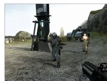
in the computer world. Examples of first-person games are DOOM, Half-Life, and Call of Duty. When playing these games, you walk through the game world seeing only what you would see if you were there—your arms and hands holding a weapon, and your feet (see Figure 1.2). This
doesn’t mean that’s all that is present in the game. The game engine is aware of the full character’s position in the scene, but most of the body is not dis-played to you, the player. Other play-ers that might be present will see your full body (as in any multiplayer FPS game).
Character Concept 3
Ever wonder why we skip from first-person-shooter to third? Although it’s not really used, the term second person
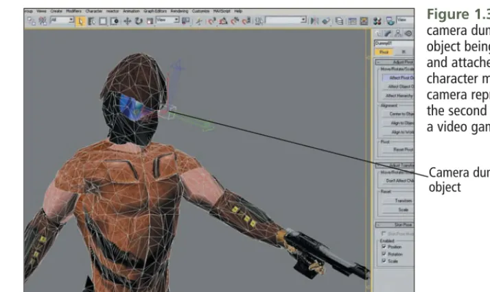
refers to the actual camera object that the game uses to display images to the player onscreen. The camera is an invisible dummy object, usually rep-resented by a simple small box model you create. This object is technically part of a character mesh, attached to a point on the character’s body, usually located between the character’s eyes. The orientation of the object (that is, its X-, Y-, and Z-axes) is aligned in a specific direction, usually with the
Y- or Z-axis pointing forward to the game world. The camera object’s name, location, and orientation are specified by the game programmers, who use these objects in the program-ming code to properly display the game to the player. Figure 1.3 shows what the camera object looks like when developing a character model.
Dummy objects are used for other things like weapon placement and character attachment points (such as where the player’s hands and feet go when he’s hopping onto a vehicle). I will explain more about this in
Chapter 7, “Rigging a Character with Biped in 3ds Max.”
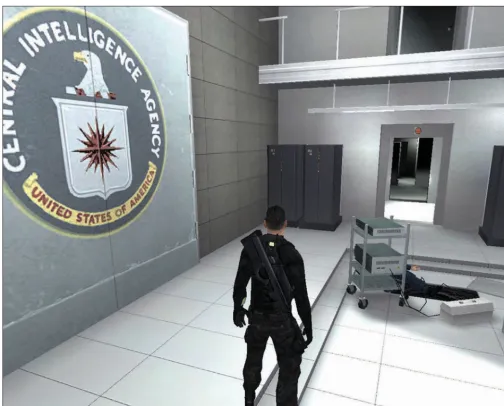
A third-person-style game is similar to first-person in that you are still controlling the main character but you see the world through the eyes of an orbital, or positional camera. Not only can you see your player character in full detail, but you can position your world view around the character and in almost all directions (see Figure 1.4). The reason that this style is labeled third person is that you are no longer “in the game world” but
viewing the world from outside of your player character. Examples of games like this are Tomb Raider,
Hitman, and Splinter Cell. The camera object floats behind the player charac-ter, and both move together through the game world but also independent-ly of one another.
Some games allow you to switch between first- and third-person per-spectives, but both styles have the same character model specifications. The polygon count, textures, and ani-mations are the highest quality of any
Figure 1.3 A camera dummy object being placed and attached on a character model. The camera represents the second person in a video game.
Character Concept 5
other model in the game because the player constantly views them.
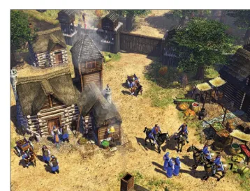
Lastly, there are what I consider fourth-person-style games. Tech-nically, these are still third person, but instead of controlling one player character, you control many, as in the
Age of Empires series, Diabolo, and even Call of Duty and Brothers in Arms (when controlling multiple characters at once). I want to single outAge of Empiresand that respective style because the character models are small and usually viewed from afar (see Figure 1.5). This is a strategy game, but having the characters so small means that the polygon count and texture maps are also small. This is important because it means you shouldn’t spend too much time creat-ing a complex game character—the polygon count is low, and there is only a handful of animations.
Taking into consideration the style of game for which you are creating a character is important so that you know how detailed your character will be. A first- or third-person game character, as the player model, has rel-atively high polygon counts for the
mesh, detailed textures, and dozens of animation sequences. Computer AI characters also have high quality and most likely incorporate many facial expressions and lip-syncing anima-tions.
Character Type
This book describes how to develop a first-person game character in detail. Creating monsters and enemies is fun but not as detailed, because opposing characters either don’t wield weapons
or drive vehicles, or they have only one weapon. In conceiving of a char-acter type, know beforehand some of the character’s attributes. If a charac-ter is human or humanoid, the process of adding a skeleton to a 3D mesh will be easy because most 3D programs like 3ds Max 8 have a default skeleton that takes on a humanoid form. If your character is to be, say, a six-legged monster with two tails and a goofy long ponytail, you’ll have to manipulate a humanoid skeleton to fit and drive the character mesh.
The weapon models that a player character uses also drive its polygon count and animations. Different weapons require different postures and attachment locations and some-times force you to increase the poly-gon count on the model at joint areas so that the model flexes more natural-ly. Multiple dummy objects are also needed so that the game engine knows where on a character a weapon should be attached or what limbs of the character should attach to certain points on a vehicle or other object.
A background story for the character in question is important because it
dictates many attributes such as how the character looks, moves, and sounds throughout the game. The background story also provides a his-tory for your character and is usually documented in reference material printed while and after the game is published. In Chapter 2, “Preparing to Model: Configuring 3ds Max and Referencing Sketch Art,” I develop a character concept and background story in conjunction with some sketch art to be used for creating characters throughout this book.
Sketch Art
Generally, a sketch artist in a game company spends his time drawing game characters on paper for the 2D/3D artists to use as a visual refer-ence during character creation. As a character artist, you don’t normally spawn your models and animations on your own—you work closely with the concept/sketch artists and pro-grammers and create models via their ideas and recommendations. In the next chapter, I show you how to use sketch art images on 3D modeling planes so that you can use them as a reference for modeling a character.
Modeling
Modeling is the most complex task when creating a game character and is the heart of this book. I’ll show you how to model (and animate) a charac-ter from scratch using 3ds Max 8, but the techniques are similar with other popular 3D modeling programs. 3ds Max is an extremely versatile and widely used graphics tool for games, television, and film, but because of this, it carries with it a significant price tag (approximately $3,500). This is typical of higher-end graphics soft-ware. I’ve heard complaints from readers about my election to write about software that’s unaffordable; my response is that nearly all game development companies use these packages, and as an artist, you must be an intermediate to advanced user of at least one of them. Table 1.1 lists a number of popular modeling pack-ages, their prices, and Web sites.
The CD-ROM that accompanies this book contains the demo version of 3ds Max 8. You’ll be able to follow every example in this book using it, if you don’t already own Max. Note that the demo works for only 30 days, though.
N o t e
If you’re looking for some freeware and shareware 3D tools to play around with, check out Blender 3D at http:// www.blender3d.org and MilkShape 3D at http://www.swissquake.ch/ chumbalum-soft. Note that they have limited ability for creating game con-tent. In fact, I can’t think of a single published game developer who uses them. The higher-end stuff is far more powerful, with Max, Maya, and SoftIm-age as the frontrunners for game mod-eling, animation, and special effects.
Modeling Techniques
You can employ many modeling tech-niques to create characters, such as spline, subdivision surface, NURBS, and box modeling. We’ll be using the box modeling technique to physically shape the character—that is, creating a rough 3D model by tracing perspec-tive character sketches on reference planes, in combination with some subdivision surfacing. The model will initially be boxy in shape, but after applying a smoothing modifier in 3ds Max and increasing the polygon count in critical areas, the character will come into focus nicely. Box
modeling is a more precise, less detailed way of modeling that is per-fect for game characters. It allows you to rapidly develop a character that is shaped just like the sketch art and has a lower polygon count than other modeling techniques. As of 2006, the average 3D video game’s characters have around 5,000–7,000 faces that comprise the 3D mesh. This will be our target count because any higher count would slow down the computer during gameplay. However, as com-puter speeds increase, this number will also increase. Movie characters can contain upward of 100,000 faces
per model, but that is currently not feasible to render in real-time gaming.
N o t e
Apolygonis a 3D structure consisting of three or more points called vertices
that are connected in 3D space with lines called edges. The smallest poly-gon is simply a triangle serving as the basic unit of measurement for a 3D model. Several polygons together com-plete a mesh object that can be deformed and animated, as you will see in later chapters. A target polygon count refers to the target face count of a model.
Table 1.1
3D Modeling Programs Used in the Game Industry
Program Version Company Price Web Site
3ds Max 8 Autodesk $3,500 http://www.autodesk.com Maya 7 Autodesk $2,000– http://www.autodesk.com
$6,000
SoftImage|XSI 5.0 Avid Technology $2,000 http://www.softimage.com/ home/
LightWave 3D 8 Newtek $800 http://www.newtek.com ZBrush 2 Pixologic $489 http://pixologic.com/home/
home.shtml
Repairing, Adjusting, and
Optimizing
When you are finished modeling a character, you must fix and finalize it so that it can be properly UV mapped for the texturing process, properly animated without invalid mesh defor-mations, and work properly in a game without producing game engine errors. On first pass, you will analyze the character mesh for holes—that is, places on the model where faces are not connected with other edges. This will cause render problems within the game engine and in some cases will cause the engine to bail out complete-ly from gameplay. Fixing these holes is a matter of creating new edges to link the faces. 3ds Max has STL Check and Patch Holes modifiers that help auto-mate repair of your mesh.
Another step in the character creation process is UV mapping—preparing your model for texturing. Before UV mapping, it is good practice to model your character with mapping in mind to make the UV unwrapping process easier, as I will explain in Chapter 5, “UV Mapping the Character in 3ds
Max.” Here we’ll dissect the mesh into body parts and lay them out flat so that we can texture them in Photoshop. Having the polygons of the mesh nice and even at the seams of the model will make the UV map-ping process easy. You’ll also check your mesh for crossed vertices. When two vertices are crossed, their edges that link them to other vertices over-lap one another. This means that if a texture were wrapped around the character mesh, the crossed areas would distort the texture. Repairing crossed vertices is a matter of moving them to their proper positions in 3D space.
Lastly, optimizing the mesh helps reduce the overall face count of the model. We’ll do so by welding togeth-er suptogeth-erfluous vtogeth-ertices and deleting any stray ones. Also, certain areas of the mesh need to have their polygon counts increased somewhat to allow for smoother deformations, such as bending limbs. These areas are the knees, elbows, biceps, shoulders, neck, and particularly the face (for smooth lip-syncing movements).
3D Modeling File Types
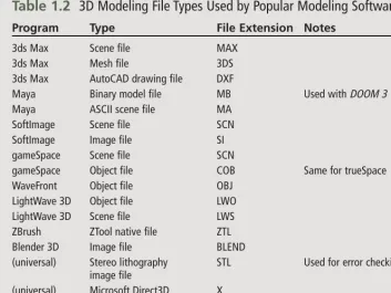
Table 1.2 lists the file types and their extensions used by the programs shown in Table 1.1. Some of these files represent an entire 3D scene in a pro-gram, some are proprietary to the particular software, and others are universal between programs. This is a handy list because you might need to import or export files among several programs.
3ds Max is capable of importing from and exporting to several of these file formats; other formats require free plug-ins available on the Internet. (See Appendix B, “Related Web Sites and Links,” to find links to these plug-ins.)
UV Unwrapping and
Mapping
This next phase in character develop-ment involves preparing your model to be textured. As I briefly explained earlier, a model consists of a large number of points called vertices, and these points are connected via edges to make up a mesh object. Every ver-tex in 3D space has an X, Y, and Z
coordinate that defines its location in that space. When a mesh is created in a modeling program, a duplicate set of invisible vertices is also created, called texture coordinates,orUVs. By default, these vertices occupy the same space as the mesh vertices and are used to define how the texture bitmap wraps onto the model.
The letters uandv(and sometimes w) are initially the same coordinate values of the X, Y, and Z coordinates of a 3D model. After you’ve finished creating your character model, it is your job in 3ds Max to create a UV texture map so that you can use a program like Photoshop to paint a texture using this map as a reference. A texture map
is two-dimensional; the X coordinate is horizontal and the Y coordinate is vertical, just like in planar geometry. In Max, UV mapping involves taking apart the texture coordinates and pro-jecting them flat on a texture map plane. This is analogous to cutting a t-shirt at the seams and laying the pieces flat on a square surface.
During the UV process, a model’s tex-ture coordinates have been separated at “seams” and laid flat on a UV work-space. When the points here are no longer in 3D space, they do not have a third dimension, or W value—hence the term UV. From here, you can copy this map to Photoshop, paint it, and use the image in Max to texture your model. At this point, when anytexture map is applied to your model, it is wrapped around the model according to the new UV layout. Also note that the model’s vertices are unaffected by the UV coordinate manipulation process.
UV mapping is somewhat complex because you must take time to prop-erly cut apart the UV vertices at hid-den areas called seams. For instance, if you cut the front of a t-shirt up the middle, the texture will display a
Table 1.2
3D Modeling File Types Used by Popular Modeling Software
Program Type File Extension Notes
3ds Max Scene file MAX
3ds Max Mesh file 3DS
3ds Max AutoCAD drawing file DXF
Maya Binary model file MB Used with DOOM 3
Maya ASCII scene file MA SoftImage Scene file SCN SoftImage Image file SI gameSpace Scene file SCN
gameSpace Object file COB Same for trueSpace WaveFront Object file OBJ
LightWave 3D Object file LWO LightWave 3D Scene file LWS ZBrush ZTool native file ZTL Blender 3D Image file BLEND
(universal) Stereo lithography STL Used for error checking image file
visible seam right up the middle because this is the start and end point around which the texture is wrapped. It is ideal to instead cut the vertices along the sides of the model so that the seams are not quite visible to the player.
Sometimes vertices might be crossed or the geometry might be invalid, causing kinks or errors in the UV map. It is also common practice to create a checkerboardmap, to make it easier to view these errors.
Notice from Figure 1.1 at the begin-ning of this chapter that the UV map-ping process bounces back and forth between modeling and texturing. You’ll be doing this as you preview your texture and make model adjust-ments to finalize your character.
Texturing
Later in this book, I will be showing you how to use the UV map you’ve created for your character model to paint a 2D bitmap, or texture. This map is a square image file that dis-plays colors and faux detail to your model as your game engine renders it in real-time. Until recently, texturing
was a fairly simple process of painting images onto a UV map in Photoshop and using a program like 3ds Max to apply the texture to a model. With increased game quality, characters and other objects now have multiple texture attributes and layers aside from just a texture map. Such attrib-utes can be grouped to form a shader, such as specularity, glossiness, ambi-ent and diffuse colors, reflection, self-illumination, and transparency. A model’s overall texture could contain layers of texture maps and
shaders, bump maps, and normal maps. The combi-nation of several of these properties makes your character appear much more lifelike and assists in speeding up rendering, because the game engine is now rendering texture maps to create a faux finish instead of having to render an extremely high polygon count model. In Chapter 6, “Skin Texturing with Photoshop CS2,” I will show you how to create a high-quality,
multiple-attribute texture that is suitable for a modern video game.
Shaders
A shader is a predefined set of lighting and rendering parameters, created by programmers or by you, that tells both modeling and game software how to render a texture map. A map rendered by itself can be dull or flat without some specific attribute or shader applied to it. For instance, in Figure 1.6, the sphere on the left is rendered
Texturing 11
with a simple diffuse texture map with general ambient lighting. The sphere on the right has the same map, with a metal shader applied. This shader contains rendering specifications like specularity and glossiness, making the object appear to be metal.
Some video games like DOOM 3take advantage of shaders and other tex-ture attributes to create spectacular game imagery without sacrificing processing speed. In general, game programmers and the software devel-opment kits (SDKs) they create will provide documentation as to what types of textures and shaders you should apply to your models.
Bump Maps
A bump map isn’t really a texture but is used in conjunction with one to simulate 3D surfaces on a 3D object. This generally reduces the polygon count of an object; instead of meshing out, say, a bumpy dinosaur skin by creating a 20,000-polygon model, you can use a bump map and a 2,000 polygon-count model to simulate this detail. The bump map is a grayscale map that the game or modeling engine uses to provide artificial relief
on the existing texture (see Figure 1.7). The engine interprets the varying shades of gray, with white being the highest and black being the lowest.
There’s also a disadvantage to using bump maps. For the relief, or visual depth, on the rendered model, the light source always seems to come from one direction—usually above. An advanced technique to providing a much better relief that changes with lighting direction (and makes the model appear extremely detailed) is using normal maps.
N o t e
Although people often use the words
bump map and displacement map
interchangeably, a displacement map is more appropriately a term for a texture map that creates the relief for a terrain. A game engine can use a displacement map, which is similar to a grayscale bump map, to create a height map for the terrain in a game. The engine trans-lates the shades of gray on the map to build a surface accordingly. The more white on the map, the higher the ter-rain’s surface; the more black on the map, the flatter the surface.
Figure 1.7 A bump map gives the model the illusion of a 3D texture during render time.
2D texture
Bump map
Normal Maps
Anormal maprefers to a color-coded bump map that the game engine can use to dynamically render faux 3D surfaces on a model from any direc-tion. Unlike a grayscale bump map, whose relief is only applied to the model on a per-vertex basis, a normal map provides relief on a per-pixel basis, using the colors in the map to create artificial normals on the object’s faces. First let me explain what an object’s surface normals are and how an object reflects light in a program.
Every face, or triangle, on a 3D model has an invisible attribute called a nor-mal, which is a vector pointing away from and perpendicular to the face. This vector is a line that the rendering software uses to determine how the light in the scene should reflect from the face. In essence, the greater the angle that the normal is from the direction that the light source is pointing at the model, the darker the face appears in the scene. Conversely, face normals that point closer to the direction of the light source appear lighter.
Until recently, modeling and game software rendered each face of a model, based on the face’s normal, by creating a lighting gradient and shading the face appropriately by interpolating the adjacent normals of the vertices that made up the model’s mesh. This is known as per-vertex shading, or Gouraud (“goo-row”) shading. Although it provided some lighting realism, it wasn’t a smooth rendering technique. With the advent of newer DirectX shading technology and video cards that could handle it, per-pixel shading came of age. This meant that faces on a model could be lit on a per-pixel basis according to a normal map.
Anormal mapis a texture map that a rendering program uses to generate individual pixel normals for the faces on an otherwise low resolution (low polygon count) model. The normal map is a red-, green-, and blue-shad-ed image that dictates how the faces of a model should be lit. The program looks at the colors on the map and interprets them as a height map, where individual pixels on the map represent vectors. The red, green, and
blue values of the normal map are respectively interpolated as X-, Y-, and Z-coordinate values for individual normals. The software then illumi-nates the faces of a model according to the values of these normals.
This process might seem complex, but it really isn’t. In Chapter 6, I will show you how to create normal maps and apply and render them in real-time.
Texture Map File Types
I’m going to wrap up this section with some of the primary image formats you’ll be using when saving your work. Each file format offers different techniques of saving image informa-tion, content, and compression. Your general file-format options are these:
■ PSD
The format in which you save your texture map depends on the game engine you’re using. See Table 1.3 later
in this chapter for a list of different engines and their respective texture specifications.
PSD
The default image format in Photoshop is PSD. When you create an image, all the components of the image such as layers, styles, channels, and paths are stored in the PSD file. Always save your original work in this format first, and then save it in anoth-er format. If you don’t save your image as a PSD but need to go back to make a modification, you’ll simply open a flattened image without the original layers.
BMP
This is the Windows Bitmap file, based on an 8-bit (256) color palette. Typically, you’ll create an image in 24-bit color mode; when you save it as a BMP file, the colors in the image are palletized to 8-bit. The original Half-Lifeengine uses this format. The BMP format has been updated from its original format to handle 24-bit images in addition to 8-bit.
JPG (JPEG)
This is the Joint Photographic Experts Group file format, invented primarily for optimizing file sizes for things like the World Wide Web. It offers decent quality with high compression.
PCX
ZSOFT developed this popular for-mat as a proprietary forfor-mat for its PC Paintbrush program back in the DOS days. PCX has a better compression ratio than BMP but retains the same image quality. The UnrealandUnreal Tournamentengines use this format.
PNG
The Portable Network Graphics for-mat is one of the best ways to preserve image data and have compression at the same time. I’m not sure why PNGs aren’t used more often; this graphics format has lossless, high compression with the capability of storing alpha (transparency) infor-mation. This format was designed to replace the popular GIF format and be seamlessly portable between com-puter systems. Garage Games’ Torque engine uses the PNG format.
TGA
The Targa format, developed original-ly for the TrueVision video board, is used often when saving animation frames in 3D programs due to the high-quality image content-to-compression ratio. TGAs also store layers and transparency channels, and they’re used within the Quake engine for images requiring transparency information.
TIF (TIFF)
The Tagged Image File Format is another high-quality image format that allows for storage of layers and transparency, just as with PSD files. The downside is its compression. TIF files are high quality, but they’re usu-ally huge.
Skeletal Rigging
moved cause the surrounding mesh to move with them. These bone objects are invisible during render time.
3ds Max 8 has an integrated set of fea-tures called biped that is used to implement a humanoid skeleton into your model. You can adjust this skele-ton in many ways to suit all forms of a character, from humanoid to animal. By default, the skeleton mimics the way a human body can move in real-time by using preprogrammed inverse kinematics (IK). A biped skeleton (more commonly known as a rig) moves naturally using IK. For instance, if you pull on the hand object of the rig, the skeleton’s fore-arm and upper fore-arm move with it nat-urally, as if you were to grab and pull on the hand of a person.
Rigging a character involves properly sizing and adjusting a rig to fit the dimensions of your character’s mesh. After you’ve aligned and shaped the bones of the rig properly, you attach the mesh to the rig through a skin modifier in 3ds Max. This modifier enables the mesh to move, or deform,
along with the movements of the rig’s bones. You then make adjustments to both the mesh and the rig so that your character animates without bizarre bends or kinks. See Chapter 7.
Animating
At this stage in character develop-ment, your model is complete with a mesh, some textures, a skeletal rig, and dummy nodes. What is left is to create individual animation sequences that a game engine will call depending on the player’s actions in a game. If you’ve played some popular 3D games (and I hope you have), you’ve seen dozens of these sequences, nearly all of which are created manu-ally by an animator or by motion cap-ture. The rest of the animations might be rag-doll effects generated by soft-ware such as the Havok physics engine. A typical player character in an FPS can have 50–100 animation sequences.
Also contained within 3ds Max is a fairly powerful animation tool that allows you to key-frame your rig with user-defined footstep patterns in
combination with natural physics effects. Key framing is a process whereby you define start and end positions of a basic motion for your character. Then Max fills in the in-between animation frames. For instance, instead of having to create every frame of movement to make a character crouch and stand up, you make two postures (standing and squatting), tell Max the total number of frames, and let it create the rest of the frames. The two postures you cre-ate are called key frames, and the process of filling in the frames that Max performs is called tweening.
Max also allows you to import MoCap (motion capture) files that drive your rig and the 3D mesh sur-rounding it. MoCap is a much better alternative to creating animation sequences because it involves captur-ing the actual motions of a human actor in a studio and porting them to your character rig. This is an expen-sive process because it requires a large studio with special image-tracking cameras positioned in three axes. An alternative could be purchasing pre-made MoCap files, but I will show
you how to manually create some ani-mations for your character in Chapter 8, “Character Animation in 3ds Max.”
Some games like Half-Life 2 incorpo-rate a purchased physics engine, such as Havok, to provide realistic, dynam-ic character behavior instead of using predefined animations. For instance, if an opponent is killed and falls from a ledge onto other objects, you can see the aforementioned rag-doll effect— the character tumbles like a rag doll, with arms and legs flopping around as they react to being struck. These are animations that the game engine pro-vides on its own instead of calling premade sequences.
You save as files each of the animation sequences you create and name them according to whatever programmers want to call them, such as player_walk or player_jump. Then, when a user presses a certain key or button or uses the joystick in a certain way, the game calls up a particular animation sequence related to that action. After you create all of the animation files, you can package them along with the
character mesh, textures, and skeleton and export them from Max to a pro-prietary game file format using spe-cial Max plug-ins that are designed for that game.
Game Engine
Exporting
When you’re finished creating charac-ters and animations, the final step is to port them to a game. Whether you’re working in-house for a game company or creating a character for a published game, you need to encode your work and pack it into one or sev-eral files designed for the game engine in question. Many pre-existing games also come with SDKs that contain documentation and plug-ins for use with Max, Maya, and other software packages so that you can export your character properly.
Engine File Types
Many of the popular FPS-style games you might have played are based on a handful of available game engines. An
engineis the complex million lines of
code written by well-known develop-ers like id Software. Typically, a game company purchases a game engine and modifies it to make its own game, but the file types and formats remain consistent with the engine. Table 1.3 lists a number of popular game engines and some helpful file infor-mation and extensions.
Summary
Summary 17
Table 1.3
Typical Game Engine File Specifications
Game Engine Texture File Model File Animation Engine Games Using This
DOOM 3 TGA MD5MESH MD5ANIM DOOM 3, Quake 4
Quake 3: Team Arena JPG/TGA MD3 MD3 Return to Castle Wolfenstein, Metal of Honor,
Call of Duty 2
GoldsourceQuake BMP MDL MDL Half-Life, Counter Strike, Day of Defeat
Valve’s Source TGA/VMT/ VTF MDL MDL Half-Life 2, Vampire: Bloodlines
Unreal PCX/UTX USX UKX Unreal, Unreal Tournament, Deus Ex
UnrealEngine 2.5 (Warfare) PCX PSK PSA Unreal 2, Unreal Tournament 4, Splinter Cell (1, 2, 3)
19
B
efore modeling this book’scharacter, I want to walk you through changing some of the default settings in Max and then pre-sent some orthogonal sketches of the character that I will show you how to create throughout the book. I’m going to assume that you’ve just installed 3ds Max 8 (either the full version or the demo on the CD-ROM) but that you are somewhat familiar with the Max environment. Please note that this is not a beginner tutorial on the usage of 3ds Max 8; I will, however, be straightforward in telling you what to do in every tutorial. Also note that if
you need additional information or assistance on any subject, you can click on Max’s User Reference in the Help section.
Adjusting the hardware and software settings in Windows and Max is important because much of the graphics work depends on having these proper configurations. I strong-ly urge you to read this chapter for details on creating the proper model-ing environment before you begin your work. Having quality sketch art to follow when modeling is also important because it allows you to properly and accurately model your character. In this chapter, I will review
■ Installing the latest version of DirectX 9 to take advantage of Direct3D shaders in Max and video games
■ Having the proper video card that can handle DirectX functions
■ Setting your Windows graphics environment to display your graphics at the highest resolution
■ Configuring the Max environ-ment in preparation for model-ing your game character
■ Applying orthogonal sketch art to 2D planes in Max so that you can use them as a reference when modeling
Preparing to Model:
Configuring 3ds Max and
Referencing Sketch Art
Hardware and
Soft-ware Considerations
The graphics capabilities of 3ds Max are somewhat limited by your com-puter’s hardware and software. You need to configure your system prop-erly so that it can display high-quality 3D graphics and shaders and you can view your work in real-time as you would in an actual video game. As you might know, most video games require or prompt you to load DirectX 9c (as of the spring of 2006— soon to be DirectX 10) before they can run properly because DirectX graphics commands drive the game’s engine. Such commands also drive 3ds Max when the DirectX video mode is enabled in Max. But for DirectX to do its job, it needs to run on the proper hardware, dictated by your computer’s video card. Here I will expose you to some of the hard-ware and related softhard-ware drivers that you should have in your computer.
N o t e
The latest version of DirectX, 9c, is located on this book’s CD-ROM. It is advisable that you install it on your sys-tem before installing 3ds Max 8 and other video games.
Choosing a Proper Video
Card
You need to have a video card that supports Direct3D, the portion of DirectX that is dedicated to creating 3D graphics. Not all cards support the latest version of Direct3D, so look at the manufacturer’s specifications when selecting one. NVIDIA, which I highly recommend, is the most popu-lar 3D video chip manufacturer. I have a GeForce 5900 PCX; NVIDIA recommends a minimum of a GeForce 2 card. Another popular chip manufacturer is ATI, producer of the Radeon cards that also support DirectX 9.0c. You also need a card that supports the latest version of
Direct3D if you want to real-time ren-der your character model’s textures using 3ds Max’s DirectX .fx shaders. (See Chapter 6, “Skin Texturing with Photoshop CS2,” for details using Max shaders.)
Graphics Software and
Drivers
When you first install Max 8, it asks you in which video mode you want the program to run. With an NVIDIA GeForce 2 or greater video card installed, you should choose Direct3D. Then click on the Advanced button, make sure DirectX 9.0 is selected, and click OK (see Figure 2.1). This enables software rendering
by Max using DirectX, thereby simu-lating the real-time rendering envi-ronment produced with modern 3D video games.
If your video card doesn’t support DirectX 9, this option is unavailable, but you can still texture and real-time render your character models. (The render quality isn’t that good, howev-er.) If you’ve already installed Max and need to change to the proper Direct3D driver setup, in Max just choose Customize, Preferences, Viewports, and in the Configure Driver section, click Choose Driver to select Direct3D. Be aware that you’ll need to restart Max before you use the selected driver.
After you install and configure Max, it is also advisable that you down-load and install the latest Max 8 ser-vice pack (SP1) from http://www. autodesk.com. This patches any bugs found after the final release of Max. Also, some video cards don’t render or display graphics properly in Max or other video games unless you have the most recent video card drivers installed in Windows. You can down-load these from your card’s manufac-turer. (See Appendix B, “Related Web
Sites and Links,” for more hardware sources.)
Monitors and Settings
A final note on properly displaying your graphics work is to have a large monitor and high-quality video mode settings in Windows. A decent moni-tor should be at least 17 inches diago-nally, which is standard nowadays and fairly inexpensive. Since 1997, I’ve had a 21-inch monitor (a mere $1,100 back then), but I’ve seen them go for as little as $250 with shipping on http://www.ebay.com. A large moni-tor lets you view more of your work in progress. Also, give your graphics view greater quality by setting the dis-play resolution in Windows to at least 1280×1024 at 32-bit color depth. The color setting is important because 32 bit displays alpha (transparency) information when texturing. Change these settings by right-clicking on the Windows desktop; clicking Properties, Settings; and changing the Colors and Screen Area accordingly. Finally, click on the Advanced button and choose the Monitor tab. Change the Refresh Rate to the highest fre-quency setting that your monitor
allows; doing so eliminates that inter-laced flickering you might see at high-er resolutions.
C a u t i o n
Be careful not to set your Refresh Rate in Windows to a value higher than rec-ommended, or you will risk perma-nently damaging your monitor. Check with the documentation that came with your monitor or see the manufac-turer’s Web site for this information.
Configuring the Max 8
Environment
Here are some final adjustments you should perform in 3ds Max 8 before you begin placing reference art and modeling your game character:
1. Customize keyboard.The key-board shortcuts that are mapped by default in Max are somewhat scattered. Over the years, I’ve found that remap-ping the most commonly used functions on the left side helps me speed up my work. Having simple operations like move,
rotate, and scale on one hand while I move the mouse with the other makes modeling swift and efficient. I’ve created a list of common shortcuts and remappings for Max and Pho-toshop in Appendix A, “3ds Max 8 and Photoshop CS2 Key-board Shortcuts.” I highly rec-ommend becoming proficient at using them. You can also load the Custom.kbd file on the CD-ROM by clicking Cus-tomize, Customize User Inter-face, and clicking on Load to load this file, which contains my personal keyboard setup. 2. Set up units.Video games are
commonly designed using the metric system as a system of measurements. Therefore, when you’re creating any 3D objects intended for a game, you model them as if you are building them in real life. For instance, the character I show you how to make in this book has a height of 1.83 meters, which is exactly 6 feet tall. The grid you see dis-played in Max is ruled accord-ing to the unit setup you have specified. To tell Max to use the
metric system, click Customize, Units Setup, and choose Metric under Display Unit Scale (see Figure 2.2). Also, click the Sys-tem Unit Setup button and change the System Unit Scale to 1 Unit = 1.0 Meters. Now you can manually enter the dimen-sions, in meters, for objects that you create, and you can use the home grid as a metric reference. 3. Enable grid and snap settings.
Choose Customize, Grid and Snap Settings, click on the Home Grid tab, and change the Grid Spacing value to 1.0m.
This provides 1-meter squares in the home reference grid in your viewports.
4. Enable Transform Gizmo.
The Transform Gizmo is a moveable device with handles that appears for the X, Y, and Z axes when you attempt to move, rotate, or scale an object. Clicking and dragging the han-dles makes it easier to move an object along these axes. On the main menu, enable this gizmo by clicking Views, Show Trans-form Gizmo.
Figure 2.2
5. Zoom into grid.With the new metric grid settings and spac-ing, click on any of the view-ports and use your mouse wheel to scroll, or zoom, into the grid so that only two square meters are visible. This is the working space for your game character.
Orthogonal Sketch Art
Now let’s get to the fun part. Before we begin modeling, we need some type of sketch art images to place on reference planes in Max. Most model-ing techniques utilize front, left (or right), and top sketch art orthogonal views so that you can create the char-acter in three dimensions. For the character in this book, I’ve provided some cool sketches of a military-style android that you can use to follow the examples throughout this book (but by all means, feel free to use your own sketch art). This character fits well with some of the popular games out there, like DOOM 3 and Half-Life 2. It’s humanoid and can carry weapons, can lip-sync dialogue, and will have realistic skins with many different tex-turing techniques applied, in addition to normal mapping shaders.
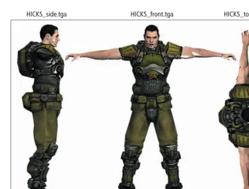
Figure 2.3 shows the three orthogo-nal sketches you can use in Max as references when building your character model. You can find them on the book’s CD-ROM, named HICKS_side.tga, HICKS_front.tga, and HICKS_top.tga. They are TGA files because they each have a separate channel representing transparency
information. For instance, in Photoshop, if you open any of these files and click on the Channels palette, you see a fourth channel that has a sil-houette of the character in white on a black background. Max interprets the black as transparent, as you see in the next section.
Orthogonal Sketch Art 23
Figure 2.3 Front, left, and top views of the orthogonally sketched HICKS #2A163. You’ll use these images as modeling references on 3D planes in Max.
The HICKS Rebuild #2A163
Background
To understand the profile of the char-acter we’re creating, let’s look into his background. This U.S. Marine cyborg, currently labeled HICKS Rebuild #2A163, was actually Corporal Dwayne Hicks from the movie Aliens. In Alien3, Hicks, Newt (the little girl), and Ripley were automatically jetti-soned to escape the planet. After jettison, Newt had drowned in her cryotube, and Hicks had been impaled by a safety beam. What the movie didn’t show you is that Hicks’ body was immediately kept in cryostasis upon discovery, and the corporation ordered his body to be reconstructed, cybernetically, and his brain reactivated. The corporation valued Hicks and Ripley because of their significant alien encounters.
Born in 2114 in the western outskirts of Belle Plaine, Kansas, Dwayne Hicks grew up in a country setting on a large farm with four older brothers and one younger sister. His parents subjected the family to labor on their farm, so he grew up with more callous than the average American. A comely and intelligent teen, he also played
football in high school and was deter-mined to join the military as soon as he was eligible. He was an unpreten-tious individual who should have been an officer but lacked the desire to acquire a college degree. Enlisting in the Marines was cut out for him.
Upon completion of his training at Parris Island boot camp at age 19, Hicks served two years in a ceaseless war in the Neptune region. He was stationed at a large military com-pound on Triton. Exhausted by this uninteresting conflict, Hicks request-ed transfer to the Xenomorph divi-sion, responsible for investigating and securing uncharted other worlds and eliminating potentially hostile alien organisms. Three years of service later, it was here in the XD that he was assigned to the elite unit that traveled to LV-426, the barren world whose colonists were killed by the infamous Alien species.
Corporal Hicks, now reconstructed as HICKS Rebuild #2A163, is fully reac-tivated in the Marine Special Forces. His mental faculty is still intact but is considered subhuman and enhanced via special neuroprocessors. Some of Hicks’ critical organs have been
replaced, as has his left forearm. He is rigged with combat-style support gear.
T i p
Reference art doesn’t have to be sketch art. It can be something as simple as taking pictures of a real person from the front and sides. Pictures of a char-acter model from a hobby shop can do just as well. Just make sure your char-acter’s poses are with the arms and legs spread out, because the completed model is better suited to accept the biped skeleton in this pose.
Creating Reference
Planes in 3ds Max 8
pixel dimensions of each of the respective sketches.
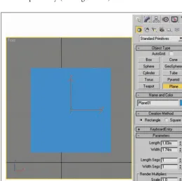
1. In Max, click on the Create panel, select the Geometry but-ton, and click on Plane. Click and drag in the Front viewport to create a plane. In the Plane Parameters rollout, change Length Segs and Width Segs to 1. Change Length and Width in the rollout to 1.83m and 1.74m respectively (see Figure 2.4).
Note that the dimensions of the front sketch, HICKS_front.tga, are 810×770 pixels. (You can view this in Photoshop.) What I’ve done is translated these measurements to meters. If the character is to be 1.83m (6 feet) tall, then 810 pixels corresponds to 1.83m (the height of the sketch). Therefore, dividing 1.83 by 810 and multiplying by 770 (1.83÷810×770) gives us
the relative width of the front sketch in meters while main-taining the aspect ratio of the original sketch, which is 1.74. You can do this for the other two planes, too. This keeps the dimensions of the planes con-sistent with those of the
sketches, and it makes the char-acter 6 feet tall (which is the actual height of actor Michael Biehn, who plays Corporal Hicks in the movie Aliens). 2. Open the Material editor (press
M)and select the first material slot in the top left. In the Blinn Basic Parameters rollout, click on the button to the right of Diffuse. In the Material/Map Browser screen, select Bitmap. Browse to the Chapter 2 direc-tory of the CD-ROM and select HICKS_front.tga to load this texture into the first material slot.
3. Click on the Go To Parent but-ton to return to the Blinn Basic Parameters rollout.
Creating Reference Planes in 3ds Max 8 25
4. Click the Show Map in View-port button, and then click the Assign Material to Selection button. This adds the texture to the plane (see Figure 2.5). 5. In the Blinn Basic Parameters
rollout, set the Self Illumination spinner to 100. This fully illu-minates the texture regardless of any lights present in the scene.
6. In the Blinn Basic Parameters rollout, click on the button to the right of Opacity. In the
Material/Map Browser screen, select Bitmap. Browse to the Chapter 2 directory of the CD-ROM and again select HICKS_front.tga. This texture file also contains a separate alpha channel, viewable in the Channels palette in Photoshop, that represents areas of the tex-ture that are to be transparent. 7. In the Bitmap Parameters roll-out, select Alpha in the Mono Channel Output section. Your character sketch should now be
floating in Max without a back-ground, making it easier to model (see Figure 2.6).
For your information, TGA and TIF files are capable of storing alpha channels that represent transparency information for both modeling programs and video games. If you open the HICKS_front.tga file in Photoshop and open the Chan-nels palette, you see a separate alpha layer that contains a black-and-white silhouette of
Figure 2.5 In the Material Editor, add the HICKS_front.tga texture to a material slot and assign it to the plane object.
the character sketch (see Figure 2.7). Max interprets the 100 percent black areas as fully transparent and the 100 percent white areas as fully opaque. 8. Now repeat steps 1–7 to create
additional planes in the Left and Top viewports. Using empty slots in the Material Edi-tor for each texture, use
HICKS_side.tga (810×214 pix-els) for the Left viewport plane, with Length equal to 1.83m and Width equal to 0.483m. Repeat with HICKS_top.tga (217×770
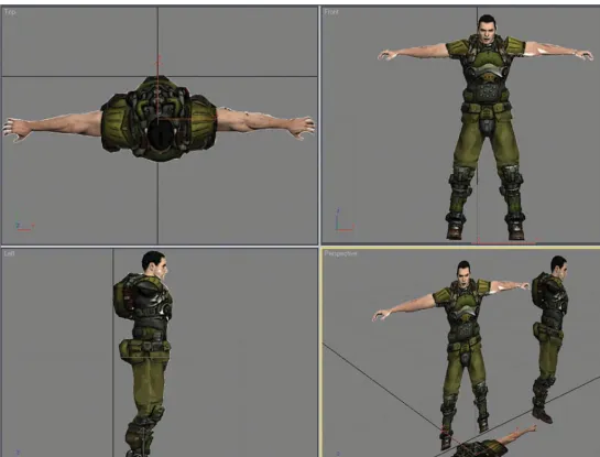
pixels) for the Top viewport plane, with Length equal to 0.49m and Width equal to 1.74m. When you’re finished, use the Move tool to position all three planes so that their edges meet and form a model-ing studio, as I have done in Figure 2.8.
9. Finally, it’s helpful to freeze each plane so that you don’t accidentally move them when modeling. Right-click a plane and choose Properties. In the Object Properties screen, check
Freeze. Then uncheck Show Frozen in Gray. Click OK, and repeat for the other two planes. If you need to unfreeze these planes at any time, just click on the Display panel, and in the Freeze section, select Unfreeze by Name.
N o t e
You can see the completed virtual stu-dio setup by opening the HICKS_ studio.max file located on the book’s CD-ROM in the Chapter 2 folder.
Creating Reference Planes in 3ds Max 8 27