IAEA HUMAN HEALTH SERIES
No. 6
RELATED PUBLICATIONS
www.iaea.org/books
Quality assurance for Pet and Pet/ct systems
Human Health series no. 1
STI/PUB/1393 (145 pp.; 2009)
ISBN 978-92-0-103609-4 Price: €32.00
iaea Quality control atlas for scintillation
camera systems
STI/PUB/1141 (293 pp.; 2003)
ISBN 92-0-101303-5 Price: €99.00
Quality management audits in nuclear
medicine Practices
STI/PUB/1371 (57 pp.; 2008)
ISBN 978-92-0-112108-0 Price: €25.00
IAEA HUMAN HEALTH RELATED PUBLICATIONS
The mandate of the IAEA human health programme arises from Article II of the Statute, which states that the IAEA “shall seek to accelerate and enlarge the contribution of atomic energy to peace, health and prosperity throughout the world”. The programme aims at enhancing the capabilities of IAEA Member States in addressing the prevention, diagnosis and treatment of health problems through the development and application of nuclear technology and related quality assurance.
The IAEA human health related publications provide information in the areas of radiation medicine, including diagnostic radiology, radiotherapy and nuclear medicine, dosimetry and medical radiation physics, and stable isotope techniques as well as other nuclear applications in nutrition. The publications have a broad readership and are aimed at meeting the needs of medical practitioners, researchers, academic teachers and students, laboratory staff and instructors. International experts assist the IAEA Secretariat in drafting and reviewing these publications.
There are two categories of publications: the IAEA Human Health Series and the IAEA Human Health Reports.
IAEA Human Health Series
Publications within the IAEA Human Health Series present analyses or provide information of an advisory nature, for example, guidelines, codes and standards of practice and quality assurance manuals. Monographs and high level educational material, such as graduate texts, are also published in this series.
The book covers of the series are colour coded, targeting different professional interests of the readership. The coding system is as follows: the blue cover is assigned to publications dealing with nutrition; the orange cover relates to clinical aspects of nuclear medicine; the green cover is given to publications discussing clinical aspects of radiation therapy and radiobiology; and the purple cover is associated with dosimetry and medical radiation physics aspects of diagnostic radiology, radiation therapy and nuclear medicine, and related quality assurance, as well as other topics in the area of medical physics.
IAEA Human Health Reports
The IAEA Human Health Reports provide information in specific areas of radiation medicine, dosimetry and medical radiation physics, and nutrition. The publications include reports of technical meetings, the results of IAEA coordinated research projects, interim reports on IAEA projects, and course material for training programmes dealing with subjects related to human health subjects. In some cases, these publications provide supporting material for those issued in the IAEA Human Health Series.
All of these publications are also available at:
http://www.iaea.org/Publications/index.html Further information is available from:
The following States are Members of the International Atomic Energy Agency:
The Agency’s Statute was approved on 23 October 1956 by the Conference on the Statute of the IAEA held at United Nations Headquarters, New York; it entered into force on 29 July 1957. The Headquarters of the Agency are situated in Vienna. Its principal objective is “to accelerate and enlarge the contribution of atomic energy to peace, health and prosperity throughout the world’’.
QUALITY ASSURANCE
FOR SPECT SYSTEMS
INTERNATIONAL ATOMIC ENERGY AGENCY VIENNA, 2009
IAEA Library Cataloguing in Publication Data
Quality assurance for SPECT systems. — Vienna : International Atomic Energy Agency, 2009.
p. ; 24 cm. — (IAEA human health series ; ISSN 2075–3772 ;
no. 6) STI/PUB/1394
ISBN 978–92–0–103709–1 Includes bibliographical references.
1. Single photon emission computed tomography — Quality control. I. International Atomic Energy Agency. II. Series.
IAEAL 09–00585
COPYRIGHT NOTICE
All IAEA scientific and technical publications are protected by the terms of the Universal Copyright Convention as adopted in 1952 (Berne) and as revised in 1972 (Paris). The copyright has since been extended by the World Intellectual Property Organization (Geneva) to include electronic and virtual intellectual property. Permission to use whole or parts of texts contained in IAEA publications in printed or electronic form must be obtained and is usually subject to royalty agreements. Proposals for non-commercial reproductions and translations are welcomed and considered on a case-by-case basis. Enquiries should be addressed to the IAEA Publishing Section at:
Sales and Promotion, Publishing Section International Atomic Energy Agency Vienna International Centre
PO Box 100
1400 Vienna, Austria fax: +43 1 2600 29302 tel.: +43 1 2600 22417
email: [email protected] http://www.iaea.org/books
© IAEA, 2009 Printed by the IAEA in Austria
FOREWORD
Quality control is crucial to all aspects of nuclear medicine practice, including the measurement of radioactivity, the preparation of radiopharmaceuticals, the use of instrumentation to obtain images, computations to calculate functional parameters, and the interpretation of the results by the physician. It plays an integral part in fulfilling the regulatory requirement for establishing a comprehensive quality assurance programme as described in the International Basic Safety Standards for Protection against Ionizing Radiation and for the Safety of Radiation Sources. In 1984, the IAEA published IAEA-TECDOC-317, Quality Control of Nuclear Medicine Instruments, which addressed the quality control of radionuclide activity calibrators (also known as dose calibrators), gamma counters, and single and multiprobe counting systems, rectilinear scanners and scintillation cameras. An updated version of IAEA-TECDOC-317 was issued in 1991 as IAEA-TECDOC-602, and this included new chapters on scanner–computer systems and single photon emission computed tomography (SPECT) systems.
The rapidly increasing use of SPECT systems during the 1990s prompted the need for a further update of these publications with special emphasis on SPECT systems, planar scintillation cameras, camera–computer systems and whole body scanning systems. Since rectilinear scanners have already been, or will soon be, phased out in Member States, the current publication excludes them completely. Quality assurance and quality control aspects of instrumentation for radioactivity measurements in nuclear medicine are addressed in Technical Reports Series No. 454, Quality Assurance for Radioactivity Measurement in Nuclear Medicine.
The current publication is intended to be a resource for medical physicists, technologists and other healthcare professionals who are responsible for ensuring optimal performance of imaging instruments, particularly SPECT systems, in their respective institutions. It is intended for managers, clinicians and other decision makers who are responsible for implementing quality assurance/quality control programmes in nuclear medicine centres. It is hoped that it will play an important role in helping maintain image quality and lead to better utilization of nuclear medicine imaging instruments worldwide.
In the preparation of this publication the efforts of E. Busemann Sokole (Netherlands), R.Z. Stodilka (Canada), A.V. Wegst and R.E. Zimmerman (United States of America) are especially appreciated. The IAEA officers responsible for this publication were M. Dondi and S. Palm of the Division of Human Health.
EDITORIAL NOTE
Although great care has been taken to maintain the accuracy of information contained in this publication, neither the IAEA nor its Member States assume any responsibility for consequences which may arise from its use.
The use of particular designations of countries or territories does not imply any judgement by the publisher, the IAEA, as to the legal status of such countries or territories, of their authorities and institutions or of the delimitation of their boundaries.
CONTENTS
1. GENERAL CONSIDERATIONS . . . 1
1.1. Objective and scope . . . 1
1.2. Quality system, quality assurance and quality control in nuclear medicine . . . 1
1.9. Interdepartmental comparisons, external assessment and accreditation . . . 8
2.1.5. Basis of schemes for testing scintillation camera performance . . . 30
2.3.4. Test of intrinsic flood field uniformity through narrowed and asymmetric (off-centred) PHA windows . . . 62
2.3.6. Test of intrinsic spatial resolution . . . 67
2.3.7. Test of system flood field uniformity . . . 70
2.3.8. Test of system spatial resolution and spatial linearity . . . 73
2.3.17. Test of routine spatial resolution and spatial linearity . . . 108
2.4. Operational checks . . . 113
2.4.1. Check of collimator and detector head mountings and collimator damage . . . 113
3.2.1. Test of system spatial resolution without scatter . . . 124
3.2.2. Test of scan speed . . . 127
3.2.3. Test of exposure time corrections . . . 131
3.2.4. Test of scan path separation of dual path (two pass) scanners . . . 133
4.2. Test schedule . . . 158
4.3. Acceptance and reference tests . . . 158
4.3.1. Physical and mechanical inspection of the SPECT system . . . 158
4.3.2. Test to determine the absolute size of a pixel . . . 162
4.3.3. Test of tomographic uniformity of the system . . . 165
4.3.4. Test of tomographic resolution in air . . . 169
4.3.5. Test of tomographic resolution with scatter . . . 172
4.3.6. Test of the centre of rotation offset and alignment of axes . . . 174
4.3.7. Test of slice thickness at the centre of the field of view . . . 178
4.3.8. Test of variations of uniformity and sensitivity with angle . . . 180
4.3.9. Total performance test . . . 182
4.4. Operational checks . . . 185
4.4.1. Check of routine function and centre of rotation offset . . . 185
5. CONSIDERATIONS FOR MULTIPLE HEAD SYSTEMS . . . 186
5.1. Introduction . . . 186
5.1.1. Multiple head camera planar tests . . . 187
5.1.2. Multiple head tomographic cameras — non-tomographic parameter tests . . . 188
5.1.3. Multiple head tomographic cameras — tomographic parameter tests . . . 188
5.2. Test schedule . . . 189
5.3. Acceptance and reference tests . . . 189
5.3.1. Physical and mechanical tests of the multiple head system . . . 190
5.3.8. Variations of uniformity of sensitivity with angle . . . 192
5.3.9. Total performance test . . . 193
6. CAMERA–COMPUTER SYSTEM . . . 194
6.1. Technical aspects of the system interface, digital acquisition and processing systems . . . 194
6.1.1. Introduction . . . 194
6.1.2. The scintillation camera–computer interface . . . 195
6.1.3. Static tests . . . 200
6.1.4. Dynamic tests . . . 205
6.1.5. ECG gated acquisition . . . 205
6.1.6. Software tests . . . 205
6.2. Quality assurance of imaging procedures . . . 216
6.2.1. General introduction . . . 216
6.2.2. Library of clinical studies . . . 217
6.2.3. Test of clinical software . . . 220
6.2.4. Practical quality assurance guidelines . . . 222
7. DISPLAY: HARD AND SOFT COPY . . . 228
7.1. Introduction . . . 228
7.2. Acceptance and reference tests . . . 231
7.3. Operational checks . . . 237
REFERENCES . . . 239
GLOSSARY OF TECHNICAL TERMS . . . 241
ABBREVIATIONS . . . 247
1. GENERAL CONSIDERATIONS
1.1. OBJECTIVE AND SCOPE
The objective of this publication is to provide professionals in nuclear medicine centres with detailed quality control test procedures for the scintillation camera and computer system. After studying this book, most qualified readers will be able to perform the three types of quality control tests, i.e. acceptance, reference and routine tests for the scintillation camera (also called the gamma camera) system for each of its imaging modes.
This publication focuses on the scintillation camera system, both in single and multiple head configurations, for obtaining images and quantitative data in planar imaging mode, whole body imaging mode and single photon emission computed tomography (SPECT). In addition, a section is devoted to the nuclear medicine computer of the camera system and quality assurance of nuclear medicine software. The final section addresses quality control of the digital image display.
Other nuclear medicine instruments, such as gamma counters and probes, are not discussed. Readers can find relevant information on gamma counters and probe systems in Ref. [1]. Tests and procedures for radionuclide activity calibrators (commonly known as dose calibrators) can be found in Ref. [2].
In addition to detailed descriptions of each quality control procedure, each respective section covers all tests for acceptance, reference and routine tests, recommended test frequency, test phantoms required and radiation sources, etc. Reference [3] complements this publication and assists the user with the evaluation of quality control test results.
Quality control is not a single action over a short period; instead, it is carried out through the whole life cycle of instruments, i.e. from planning and procurement to decommissioning. This process is described in general in this section and is applicable to all instruments of the nuclear medicine department.
1.2. QUALITY SYSTEM, QUALITY ASSURANCE AND QUALITY CONTROL IN NUCLEAR MEDICINE
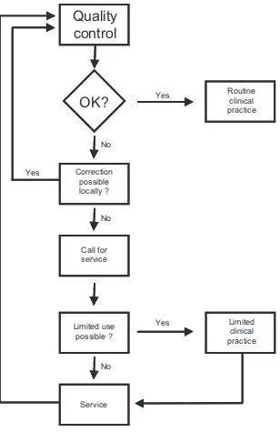
The concept of quality in the term ‘quality assurance’ expresses the closeness with which the outcome of a given procedure approaches some ideal, free from all errors and artefacts. Quality assurance embraces all efforts made to this end. The term ‘quality control’ is used in reference to the specific measures taken to ensure that one particular aspect of the procedure is satisfactory (see Fig. 1). A clear distinction between these terms should be made.
A quality system in nuclear medicine should cover all aspects of clinical practice. It includes submission of requests for procedures; the preparation and dispensing of radiopharmaceuticals; the protection of patients, staff and the general public against radiation hazards and accidents caused by faulty equipment; the scheduling of patients; the setting-up, use and maintenance of electronic instruments; the methodology of the actual procedures; the analysis and interpretation of data; the reporting of results and, finally, the keeping of records.
This publication deals with a single, albeit highly important, component of such a comprehensive programme, namely, the quality control of instruments.
1.3. PRINCIPLES OF QUALITY CONTROL OF INSTRUMENTS
A fundamental principle in the quality control of nuclear medicine instruments is that the quality control should be undertaken as an integral part of the routine work of the nuclear medicine department and should be performed by members of the departmental staff themselves. However, some aspects must be carried out in collaboration with maintenance staff.
The quality control of each instrument should have as its starting point the selection and acquisition of the instrument itself, since instruments may differ widely in their characteristics and performance. The choice of an appropriate site for installation of the instrument should likewise be considered within the scope of quality control, since it may influence performance.
Yes
Yes Yes
No No No
Correction possible locally ?
Routine clinical practice
Limited use possible ?
Service Call for service
Quality
control
Limited clinical practice
OK?
appropriate corrective action should follow. These quality control procedures do not, of course, obviate the need for the usual preventive maintenance procedures, which should still be carried out on a regular basis. The success of such a scheme depends above all on the understanding and acceptance of all concerned. It further requires a clear definition of responsibilities and adherence to test schedules, protocols and proper procedures for the follow-up of test results.
1.4. SELECTION AND PROCUREMENT
The selection of an instrument with respect to manufacturer, model, etc., should be based not only on its suitability for the particular procedures to be carried out, as judged from its technical specifications, but also on such considerations as its ease of use (ergonomics), reliability and safety in operation, its compatibility with other instruments, the facilities and personnel available for its maintenance and the availability of spare parts. Technical advice on these points is often needed and the experience of other nuclear medicine centres can be valuable in this respect.
Considerable care is necessary in negotiating the purchase of an instrument. Full technical specifications should be solicited from manufacturers. Such specifications should cover all components in the instrument and all options, and should include power supply requirements; operational limitations as to temperature, humidity, etc.; size and weight bearing requirements; requirements for expendable items such as film and special paper for some specific printers as well as the availability of such items; and compliance with international and other standards. Quotations should indicate the price and terms; the date, mode and cost of delivery; the nature and duration of warranty; and the cost and specific coverage of service contracts. Also included in the quotations should be the manufacturer’s arrangements for installation; the accessories, spare parts, manuals, test devices and expendables to be provided; the location and content of any training to be given to different categories of staff; the servicing facilities and personnel available; and the facilities for the supply of spare parts. Further, the quotation should detail the purchaser’s arrangements for acceptance testing (perhaps in concert with the vendor), the minimum acceptable performance characteristics and the action to be taken if these are not met. Quotations should be compared with all these points in mind.
facilities may well be preferred on grounds of reliability to one with outstanding performance characteristics but inadequate facilities for servicing. Maintenance of an instrument, including the supply of spare parts, has to be foreseen for its expected lifetime. This should be taken into account when costs are compared. Purchase price is an unreliable guide as to the total cost of an instrument, since it does not cover cost of repairs and regular contracted services to the nuclear medicine centre over the instrument’s lifetime.
It is imperative that fully updated operation and service manuals, written in an appropriate language, accompany every instrument. Appropriate radiation sources, phantoms and other test devices needed for quality control should be provided or separately purchased at the time of instrument acquisition. It is also important to mention that the evaluation of offers and purchase orders should be jointly prepared by the responsible administrative and technical staff as a collaborative effort. This staff may involve physicists, physicians, technologists and administrators.
1.5. CARE, HANDLING AND PROTECTION OF EQUIPMENT
Owing to the sophistication and vulnerability of nuclear medicine imaging instruments, great attention and effort should be paid to preventive measures, namely, care, handling and protection against the following main environmental conditions:
(a) Climatic environment of the instruments. A good protection programme should provide effective air conditioning and humidity, dust and pollution control, etc.
(b) Electrical environment of the instruments. A good protection programme should provide effective AC line power conditioning against lightning, power line disturbances, electrostatic discharge and electromagnetic interference. The use of an uninterruptible power supply is advised to protect the system in the event of power failure.
(c) Human environment of the instruments. A good preventive programme should provide timely education of the operators, service engineers and technicians on the correct use and protection of the instruments. Only qualified and skilled service staff should be allowed to deal with the service and maintenance of sophisticated nuclear medicine equipment. (d) Magnetic environment of the instruments. Nuclear medicine equipment is
(e) Background radiation. A good protection programme would consider, during planning and installation, the location of major radiation sources, i.e. positron emission tomography facilities, X ray machines, linear accelerators and 60Co devices for radiotherapy. Nuclear medicine instruments are extremely sensitive to these high energy sources and must be installed at appropriate distances from them. It is advisable to avoid location of radiopharmacy facilities close to the imaging rooms without proper attention to shielding. The storage and movement of radioactive materials, including patients, in the vicinity of nuclear medicine instrumentation should also be avoided.
It is imperative that all these protective measures be properly undertaken prior to installation and continue to be maintained during operation until decommissioning of the instrument, complying with current safety standards [4].
It is very important that all instructions from the operation manual and service manual for proper handling of the instrument should be carefully followed and that all the manufacturer’s requirements for protection should be properly met before its installation.
1.6. PREVENTIVE MAINTENANCE
In contrast to the care, handling and protection programme, the preventive maintenance programme is designed and implemented against possible faults to the instruments. It should be periodically carried out and checked using the necessary quality control tests. A good preventive maintenance programme should include the following main procedures:
(a) Quality checks of parts, electronic circuits, components, connectors and cabling, etc.
(b) Inspection of detector/sensor condition. (c) Checks of low and high voltage power supplies.
(d) Bias adjustment, preliminary adjustment of energy and position signals and preamplifier fine tuning, etc.
(e) Calibration of all correction circuits (e.g. energy, linearity, uniformity and attenuation corrections).
As in the case of corrective maintenance (repairs), preventive maintenance is machine dependent. As such, the protocols will differ from machine to machine. Usually, preventive maintenance is periodically carried out by qualified service engineers through contracted service. In addition, all documentation, including service manuals and circuit diagrams, necessary test tools and radiation sources, must be obtained at the procurement stage.
1.7. ACCEPTANCE AND REFERENCE TESTING
The acceptance of an instrument following its receipt and installation is a critical step towards the achievement of high quality performance and should be subject to correspondingly careful testing. Acceptance testing is undertaken to ensure that the performance of an instrument meets the technical and performance specifications quoted by the manufacturer. It should be carried out immediately after installation so that the supplier can be informed of any damage, deficiencies, or flaws before the warranty has expired. No instrument should be put into routine use unless it has been shown through acceptance testing to be performing optimally. An instrument that does not perform correctly at installation has a high likelihood of never doing so.
Acceptance testing is of concern to the maintenance staff, the manufacturer’s agent and the eventual users of the instrument and all should be involved to some degree. As already indicated, it is important to establish during negotiations for purchase the manner in which such testing will be carried out and the minimum acceptable performance characteristics. Tests should be stringent and carried out according to clearly defined protocols. If they require specialized equipment, arrangements should be made for its provision. For acceptance testing of any major instrument, a representative of the manufacturer should always be present and should be able to initiate remedial action if specifications are not met. Otherwise, the onus for this falls on the purchaser. The practice of withholding payment of a part of the purchase price until acceptance testing has been satisfactorily completed is effective in many countries.
be performed with the instrument in as good a working condition as possible at the time routine testing is initiated, in order to provide a set of reference data.
1.8. ROUTINE TESTING
Routine tests are those that should be carried out regularly on an instrument to ensure its optimum performance at all times and to determine the rate and extent of any deterioration in that performance with time. Such tests fall into two categories: the first includes tests that have been previously carried out as reference tests and that are repeated weekly, monthly, quarterly, yearly, etc.; and the second includes daily or operational checks that are to be carried out each day the instrument is used.
It is clear that routine tests should always be executed in a like manner if successive results are to be comparable. Therefore, they should be carried out according to clearly defined protocols. When appropriate, limits of acceptability for the results and courses of action to be taken if these limits are exceeded should be specified. Operational checks should be simple and so designed that they can be completed in an acceptably short time (e.g. 15 min for a scintillation camera), according to a defined sequence by an experienced person.
Unavoidably, test schedules constitute a compromise between what is desirable and what is feasible. The choice of tests and the frequencies with which they are carried out have to take account of the situation in the individual nuclear medicine department and the status of its instruments. It is important that staff in all categories develop an attitude of alertness to possible instrument malfunction and that all appropriate aspects of the nuclear medicine procedure are tested whenever clinical results are suspect. No schedule can be established for such occurrences.
1.9. INTERDEPARTMENTAL COMPARISONS, EXTERNAL ASSESSMENT AND ACCREDITATION
permits applying accurate and objective methods to measure the quality of an image. Such studies are useful in identifying malfunction of an individual imaging device and inadequate imaging practice.
Accreditation is the formal certification in relation to acceptability of a department to perform specific procedures, by an organization authorized to issue such a certification. In a rapidly increasing number of countries, success or failure of a department to achieve accreditation has a significant consequence on the reimbursement of nuclear medicine studies by the social security system. Quality control and the implementation of a quality system within the nuclear medicine department are requirements for successful accreditation. There are many components of the clinical service such as the training and competence of the staff members, the preparation and storage of the radiopharmaceuticals, referral policies and many others that contribute to the overall quality of the service [5]. The part of accreditation dealing specifically with nuclear medicine equipment addresses the calibration and quality control of equipment, validation procedures, calibration material, internal quality control, interdepartmental comparisons and how all these activities are documented.
1.10. QUALITY CONTROL RECORDS
Record keeping is of great importance in a quality management programme. The operational, quality control and maintenance records for each instrument should be assembled in appropriate log books and retained with the instrument. The records should include the results of the acceptance, reference and routine tests carried out for quality control, a record of preventive maintenance carried out and a record of failures, with details of their repair. The responsible person(s) should sign all entries. In addition, it is helpful to assemble and maintain a complete procedure manual detailing all clinical and test protocols. Indeed, such procedure manuals are required by accreditation organizations.
evidence of deterioration in performance, which may not be initially apparent. Records showing repeated failure and/or progressive degradation of performance provide unquestionable evidence for complete instrument overhaul or replacement. If the records or logbooks are set up as digital records, there must be a suitable backup of the records.
1.11. ORGANIZATIONAL ASPECTS
A basic requirement for the successful introduction of such a quality management system is that the head of the nuclear medicine department recognizes its necessity. The support of the administrative authorities is also required so that the means to carry it through can be secured. Detailed arrangements then have to be made, and responsibilities clearly defined, for acceptance and reference testing, routine testing, evaluation of test results and periodic review of results in relation to quality assurance as a whole. Regular meetings of all concerned, including both professional and technical staff, should be held for the latter purpose. Lack of adequate organization will foster a careless attitude in which tests are carried out irregularly, or only if malfunction is suspected. Proper quality control is impossible on such a basis.
A single person, generally designated the ‘quality manager’, should have supervisory responsibility for the entire quality management system and the authority to enforce it and act on its findings. This person should be responsible for overseeing all aspects of the quality system and should be involved in the evaluation and periodic review of the results. However, they need not actually undertake testing.
It is important that tests on a given instrument be carried out by a person or persons familiar with the instrument’s use. Responsibility for daily and operational tests, at least, should rest with its regular users. This has the virtue of developing in the users an awareness of the principles of quality control.
The significance of such a scheme is not limited to the individual nuclear medicine department. In some countries, a comprehensive quality management system, including the quality control of instruments, is a prerequisite for hospitals to obtain accreditation. Links with national atomic energy and health authorities, professional associations and working groups are in any case desirable, as are contacts with manufacturers and their agents. Thus, certain tests scheduled relatively infrequently and requiring special test devices may be more conveniently organized on a national basis than within the individual department. (The routine control of accuracy of radionuclide calibrators, for example, may be undertaken in this manner by a central department having the necessary certified sources.)
Interdepartmental comparisons of instrument performance, often organized on a national, regional or even international basis, may be instructive and stimulating to participating departments, as well as being of considerable scientific interest. It should be realized, however, that such quality assessment or quality surveillance schemes, usually undertaken on an occasional basis and testing either the overall performance of instruments of a particular class (e.g. scintillation cameras) or even particular performance parameters of such instruments, are in no way substitutes for true quality management systems providing continuing control of all instruments in a department.
1.12. IMPLEMENTATION OF QUALITY CONTROL
The sections that follow contain recommended schedules and protocols for acceptance and routine testing of scintillation camera systems (planar, whole body scanning, single and multiple head SPECT systems), nuclear medicine computer systems and the digital display.
2. SCINTILLATION CAMERAS
2.1. INTRODUCTION
2.1.1. Basic principles, planar scintillation camera
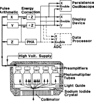
The scintillation camera is an imaging device used in the practice of nuclear medicine. It utilizes a thin but large area thallium activated sodium iodide (NaI(Tl)) crystal as the radiation detector. The crystal is viewed by an array of photomultiplier tubes (PMTs). The design of scintillation cameras varies considerably, but to illustrate basic principles, the most common camera design will be described. Figure 2 depicts a section through the detector head and the key electronic components of a typical Anger type scintillation camera. Photons emitted by radionuclides in the patient or test source reach the crystal after first passing through a lead collimator. The collimator defines the direction of acceptance of the photons. Most collimators are of the parallel hole, diverging, converging, or pinhole type. More complex collimator designs, such as fan beam, are also used.
The crystal is viewed by photomultipliers from its back surface, either directly or through a light guide. The photomultipliers are all fed from a common high voltage supply and the voltage or gain is slightly adjustable at each tube. When a photon interacts with the crystal, it produces a light scintillation that spreads through the crystal and is detected by the PMTs. The fraction of the light that strikes the photocathode of each photomultiplier varies inversely with the distance of the photomultiplier from the point of interaction. The position of the photon interaction can be determined from the amplitude distribution of the pulses from the photomultipliers in the array caused by this single gamma ray interaction. This information is used to give a spatial location to the photon interaction defined in an X–Y coordinate system (see Fig. 3).
energy deposited in the crystal by the photon interaction. Because the intensity of the scintillations increases with photon energy, and hence the photomultiplier output increases, the X and Y signals must be normalized so that the positional information is not dependent upon the photon energy. This is performed in the energy correction circuit where the X and Y signals are divided by the Z signal. Furthermore, the Z signal is sent to the pulse height analyser (PHA). If the Z signal falls within the PHA window set for the radionuclide in use, the PHA enables the X–Z and Y–Z signals to be recorded. In an analogue camera, this is usually achieved in a cathode ray oscilloscope.
The face of the oscilloscope is normally kept dark. This is achieved by blocking the electron beam from the oscilloscope face with a negatively biased grid. When the amplitude of the Z signal falls within the preset PHA window, an unblanking signal is generated, which causes the grid to become positive and allows the beam to pass. At the same time, the X–Z and Y–Z signals are used to deflect the beam, causing a brief flash to appear on the oscilloscope face at a position corresponding to that of the original scintillation. If a persistence oscilloscope is used, the flashes remain visible sufficiently long to form an image on the persistent phosphor screen. If a conventional oscilloscope is used, or an image formatting device incorporating such an oscilloscope, a permanent record is obtained by recording the flashes on film for a preset count or a preset time. The X–Z and Y–Z signals may also be digitized by analogue to digital converters (ADCs) for storage and later processing on a computer that is directly interfaced to one or more scintillation cameras. The Z pulse is used to start the digitization of the position pulses.
In ‘all digital’ scintillation camera designs, digitization is accomplished at each PMT and the pulse position is calculated by computer. This allows versatility not possible with analogue features.
2.1.2. Components of a planar scintillation camera
2.1.2.1. NaI(Tl) scintillation crystal
NaI(Tl) crystals are available in both circular and rectangular shapes. Mobile cameras and special cardiac systems have small field of view (300 mm) crystals. Large field of view (400 mm) crystals are available as multipurpose systems. Rectangular crystals with sizes as large as 400 mm × 500 mm and available in several thicknesses ranging from 3.2 to 25.4 mm are used in many single and dual headed systems. The crystal size determines, in part, the area of the patient viewed in a single image. The crystal thickness influences several performance parameters, in particular spatial resolution and sensitivity. Thin crystals yield better spatial resolution. However, their sensitivity is significantly reduced for photon energies over 140 keV. For general use, a thickness of 9.5 mm is often selected.
Any damage to the crystal results in an inoperable scintillation camera and requires costly replacement of the crystal. The large surface area as well as the hygroscopic and brittle nature of the crystal requires constant care to avoid puncturing the housing or otherwise damaging the crystal, especially in the process of changing collimators. Leaving a collimator on the scintillation camera head when it is not in use protects the crystal from mechanical shock and any rapid fluctuation in temperature. Nevertheless, sudden or gradual damage may occur unwittingly. For this reason, monitoring of the crystal is an important feature of quality control.
2.1.2.2. Photomultiplier array
high voltage to each tube. This is termed ‘tuning the head’ and is usually performed by a service representative of the manufacturer: the more photomultipliers, the more difficult the task. Daily quality control is necessary to alert the user to the need for this maintenance service.
The width of the photopeak is highly dependent upon the precise adjustment of the gains of the photomultipliers. Each photomultiplier produces a unique photopeak and when these are summed to form the Z signal, all of the photopeaks should coincide. However, because of small gain differences between individual photomultipliers, this is rarely the case; photomultipliers with gains lower than the average contribute information to the low side of the composite photopeak and those with gains higher than the average contribute to the high side (see Fig. 4).
In order to achieve a uniform flood field image, the window width of the PHA must encompass the contributions of all photomultipliers. For this reason, typically a 20% window is used. This window, centred on the 140 keV photopeak of 99mTc, would have a width of 28 keV, ranging from 126 to 154 keV. Such a window includes a significant amount of scattered radiation originating from photon interactions within the patient and leads to a loss of image resolution and contrast. Modern cameras allow the use of a 15% energy window because of linearity and energy correction circuits. If the window is offset to the high side (asymmetric high energy window) of the photopeak, the information contributed by the lower gain photomultipliers will be progressively eliminated and the image areas corresponding to these tubes will have a lower count density. Correspondingly, if the window is offset to the low side of the peak (asymmetric low energy window), the information contributed by the higher gain photomultipliers will be progressively eliminated and the areas corresponding to these tubes will have a higher count density (see Fig. 5).
If the window width is narrowed but remains centred on the photopeak, areas corresponding to photomultipliers both of lower gain and of higher gain will be progressively eliminated. Thus, uniformity across the field of view is a function of proper placement of the PHA window, which can only be achieved by daily calibration. Uniformity is also a function of the window width, photon energy and the proper tuning of all photomultipliers.
2.1.2.3. Pulse arithmetic circuits
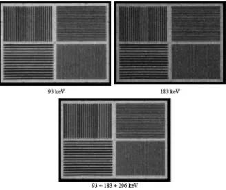
In fully analogue scintillation cameras, the X and Y position circuits are separate but identical and contain amplifiers that, if properly adjusted, ensure equal amplification in both X and Y directions, i.e. a round object will give a round image. A drift of one amplifier will cause a round object to give an oval image. For this reason, the measurement of any object-to-image parameter should be performed in both X and Y directions. Object-to-image relationships may also be affected by non-linearity in the Z signal. This is of consequence only if the outputs of more than one PHA are used simultaneously to produce a composite image, for example, in 67Ga imaging in which photons of two or three energies may be summed (see Fig. 6), or to produce a corrected image in which photons of a single energy are subtracted from those of another. If non-linearity exists in the Z signal, when the X and Y signals are divided by the Z signal, the spatial amplifications for different Z signals will differ. The superposition of several images will then result in a loss of resolution.
In cameras of more recent design, such as all digital cameras, this problem is minimized.
For a more detailed discussion and additional image examples, refer to Section 2.4 of Ref. [3].
2.1.2.4. Pulse timing circuits
The measurement of the count rate performance of a scintillation camera can be performed in several ways, depending upon the age and the design of the electronics of the system. For digital systems, the count rate performance is best tested using a decaying source and by repeatedly determining the observed count rate from a decreasing input count rate. The observed range must start beyond the maximum count rate and continue until the observed count rate reaches a low count rate (<4000 counts/s). From these data, the observed count rate at which 20% of the counts are lost can be determined (C–20%). This can be done with or without scatter. An alternative method is to use calibrated copper filters to reduce the count rate progressively. In older systems, T can be measured under conditions of only moderate count loss and with no radiation
FIG. 6. Gallium-67 multiple window spatial registration: visual method — acceptable. Intrinsic quadrant bar pattern images obtained with a 67Ga point source, 20% energy
scatter, using a two source method. From its value under these conditions, it is possible to deduce the relationship between input and observed count rates and to calculate, for example, the input count rates, R–20% for a 20% count loss, and the corresponding observed count rates, C–20%. These methods constitute useful acceptance tests since R–20% measured with no radiation scatter is a performance index specified by many camera manufacturers. The method used must be determined by consulting the product literature or the manufacturer’s representative. (It must be noted that the 1994 version [6] of the United States of America’s National Electrical Manufacturers Association (NEMA) test protocols does not include the two source method to assess count rate performance. It is included as an acceptance test in this publication since many camera specifications still include this parameter.)
FIG. 7. Changes in uniformity at high count rates. Intrinsic 99mTc images of 4 million
Parameter R–20% measured with no radiation scatter is not, however, relevant to clinical situations. In clinical imaging, scintillations due to lower energy scattered radiation arising from the patient, while not themselves displayed, may significantly increase the effective value of T. Both R–20% and C–20% measured with radiation scatter are lower than those measured without scatter: C–20% measured with scatter should not be exceeded in any clinical study. Operating the camera at higher observed count rates may compromise its spatial resolution and will only give a small increase in observed count rate for a large increase in administered radioactivity and, hence, radiation dose to the patient.
To test the count rate performance of the scintillation camera further, the intrinsic flood field uniformity and spatial resolution should be measured at count rates of approximately 75 000 counts/s.
For a more detailed discussion and additional image examples, refer to Section 2.5 of Ref. [3].
2.1.2.5. Energy, linearity and uniformity correction circuits
Several schemes have been introduced to improve the uniformity across the field of view by microprocessor techniques. The first to be introduced was based upon either adding or subtracting counts to each of the approximately 4000 elements (pixels) of a 64 × 64 matrix. The number added or subtracted is derived from the sensitivity of that pixel relative to the mean of all pixels in a previously stored flood field image. These methods are no longer used.
Scintillation cameras of newer design use a multistage process. First, to take account of photomultiplier gain variations, a small correction is applied to each Z signal, dependent upon its specific X–Y location, so that the photopeaks for all locations coincide exactly (energy correction). This results in a narrower composite photopeak and allows the use of a narrower PHA window. The second stage is the application of a small correction to each X and Y pulse, dependent upon its specific location, to eliminate spatial non-linearity (linearity correction). The correction is often derived by using an image of a series of line sources, in both X and Y directions, and computing the deviation of the image from the actual lines over the face of the crystal. A third stage may utilize a count normalization based on a previously acquired high count calibration flood (uniformity or sensitivity correction). The final image is uniform to approximately 2–3% and is essentially free of spatial non-linearity.
with the orientation of the camera relative to the Earth’s magnetic field and with temperature changes.
2.1.2.6. Display devices
A scintillation camera may be equipped with several types of display device for the purpose of visualizing the radioactive concentrations as detected by the camera. Older analogue systems use an oscilloscope that produces a flash of light on the face of a cathode ray tube at the same position on a similar X–Y coordinate system as the site of the original interaction in the crystal, or uses a multiformat imager that can place 1, 2, 4 or more images on one sheet of film by a moving lens system. Digitized scintillation camera images are displayed on a computer monitor. The quality control of display systems is presented in Section 7.
2.1.3. Basic principles, camera–computer systems
Scintillation camera–computer systems are designed to allow the collection, digital analysis and display of the image data from a scintillation camera. In fully integrated systems, the camera bed motion, uniformity correction and image collection parameters are controlled at the computer console. The components of the computer in such a system are essentially the same as those of a computer used in any other application, i.e. a central processing unit (CPU), memory and magnetic storage device. Additional hardware items necessary for nuclear medicine applications include ADCs, which convert the analogue signals: from the camera to digital numbers that the computer is able to manipulate and display as a graph or image.
2.1.4. Components of a camera–computer system
2.1.4.1. Analogue input
Special line driver circuits are commonly used to drive the low power scintillation camera signals to the computer. The use of the drivers not only ensures that the signals are not distorted but also protects the camera circuits from being damaged by the extra electronic load. The line drivers may also be used to alter the voltage levels of the signals so that they are of the magnitude required by the computer interface. Most systems have sample-and-hold circuits that retain the values of the position signals during the time that the computer is processing a detected event, even if the camera removes the signals from the line. Failures in these circuits may produce artefacts in the digital image, but usually will not affect the analogue operation of the camera. If the analogue and digital images differ, these circuits should be considered as potential sources of the problem.
2.1.4.2. Analogue to digital conversion
The X and Y position signals must be converted to digital numbers to be processed by the computer. There are several types of ADC found in camera– computer systems. The most common is the successive approximation converter, which makes sequential estimates of the required numbers. Starting with the bit representing the largest power of two, the converter sets the bit and then converts the binary number to an analogue signal through a digital to analogue converter. The amplitude of this analogue signal is compared with that of the signal being converted (see Fig. 8). If the signal being converted is smaller, the bit is turned off; if it is larger, the bit is left on. The ADC steps through each of the bits in the digital word, performing this process each time. For an 8 bit digital word (256 position values), the conversion takes eight cycles.
For a more detailed discussion and image examples, refer to Sections 2.2.2I–2.2.2L and 5.1 of Ref. [3].
2.1.4.3. Data processing
makes logical decisions. In newer computers, the boundaries of the CPU are less clear, as the single CPU is being replaced by distributed microprocessors.
Although this is important to the system designer and to a certain extent to the user, it is not important for the understanding or execution of the quality control tests to be discussed.
The computer memory consists of a series of storage locations, or bins, into which data can be placed as words for later retrieval and manipulation. Memory is characterized by the number of storage locations and the size of the individual word. The number of locations determines the amount of data and the size of programs that can be present at any given moment. The size of the memory word determines the magnitude of the number that can be stored at a given location as a binary number. Some word sizes have been given special names. The most common is the byte, which refers to a group of 8 binary digits or bits. In general, the size of the memory word determines the counts that can be collected in a digital image. Some computers allow the user to select the size that will be used for image collection. Use of an 8 bit (byte mode) storage element allows the collection of a count of only 255 per image element (or pixel). Use of a 16 bit (word mode) storage element accommodates numbers of
up to 65 535 or ±32 767 per pixel, depending on the particular computer. Computers may use other word sizes, some using up to 32 bits.
The use of an 8 bit storage element for nuclear medicine imaging may represent a limitation and a potential source of error. In imaging procedures in which the radiopharmaceutical is concentrated in a small anatomical area, the pixels corresponding to this area quickly become saturated. This is also true for test procedures that require imaging small point or line sources. Depending on the particular computer, the computer may: (i) stop collecting, (ii) continue collecting in the non-saturated areas while holding the saturated pixels at 255, thus severely distorting the quantitative data, or (iii) continue counting and allow the saturated pixel to ‘roll over’ and lose multiples of 256 counts. Each of these may cause distortion of the quantitative data unless the system is capable of performing a suitable correction. It is important for the user to understand the clinical significance of such limitations and to choose the data collection mode appropriate to the clinical study to be performed. With the speed and capacity of modern computer systems, the use of an 8 bit storage element is no longer necessary.
2.1.4.4. Image formation
The output from the ADC is used in one of two ways by the computer during data acquisition: list mode and frame mode. In list mode (see Fig. 9), the digital data representing the coordinates of photon interactions in the crystal are simply stored as lists in memory. This is analogous to a person recording
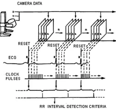
numbers on a sheet of paper. In frame or histogram mode (see Fig. 10), the digital data are used to identify the address of a specific memory location corresponding to the location of the interaction. The contents of this memory location are then increased incrementally by one. Frame mode collection constructs an image in memory buffers during collection while list mode only generates a list of interaction coordinates. Dynamic flow studies can be performed in frame mode by periodically writing the images to disk and restarting the collection in memory. A modified form of frame mode, termed electrocardiogram (ECG) gated acquisition, is often used for cardiology studies. In this mode, the data acquisition is synchronized by the patient’s ECG. In such gated acquisition, a series of frames are generated, each one representing a small segment of the cardiac cycle as shown in Fig. 11.
The number of pixels in the array or matrix into which the digital image is divided determines the capability of the computer to retain the spatial resolution provided by the scintillation camera. A camera with a larger field of view requires a larger matrix to provide the same spatial resolution in the final digital image. The choice of matrix size for a particular clinical study should be based on the analytical requirements of the study. A study that is performed primarily to perceive fine detail requires a finer matrix than one performed simply for the generation of time–activity curves from large regions of interest. The relationship between matrix size and field of view is given in Table 1, in which the size of the area represented by a single pixel is given in millimetres.
Aside from the question of spatial resolution, the choice of matrix size has an impact on the expected counts per pixel. For a given imaging situation, a change from one matrix size to the next higher, e.g. from 64 × 64 to 128 × 128, reduces the count per pixel by a factor of four, since the image is distributed over four times as many pixels. Thus, a finer matrix can sometimes be used to prevent pixel saturation, although with the use of 16 bit storage elements this should not be a problem.
TABLE 1. RELATIONSHIP BETWEEN SCINTILLATION CAMERA FIELD OF VIEW, MATRIX SIZE AND PIXEL SIZE
Field of view
(cm)
Approximate size of a single pixel (mm) 64 × 64
matrix
128 × 128 matrix
256 × 256 matrix
512 × 512 matrix 10 1.6 0.8 0.4 0.2 20 3.1 1.6 0.8 0.4 30 4.7 2.3 1.2 0.6 40 6.2 3.1 1.6 0.8
2.1.4.5. Data storage and transfer
It is necessary to provide supplementary storage in addition to that provided by the memory of the computer, for two reasons. The first is that data and information, i.e. programs and operating systems, must be transferred between computers. The second reason is that nuclear medicine imaging procedures generate a significant amount of data that must be stored for later retrieval and analysis. Magnetic storage is achieved by the use of two types of media: magnetic disk and magnetic tape. Disks are used for rapid storage and retrieval, while tape, which is slower, is used more often for long term storage and exchange between dissimilar systems. Other media that are used in nuclear medicine include optical disks: compact disk recordable, digital versatile disk and magneto optical disk.
Data are recorded on magnetic disk by read–write heads that pass over the surface of the disk in prescribed circular tracks creating small magnetized zones. The disk surface is divided into a number of storage blocks onto which the image data and programs are placed by the computer. The number and size of the data blocks are dependent on the particular disk design. In modern disk systems, the total storage capacity is extremely large and data transfer rates are very fast. Such high transfer rates may be required in high count rate studies in which counts are written to disk during collection. It is important to understand that the modern computer disk unit is a precision electromechanical device that must be properly cared for. Without appropriate preventive maintenance and careful handling, the disk unit will fail long before it should and thus prevent the rest of the computer system from operating. Failure can also result in the loss of clinical data files and software.
Optical disks write information to light sensitive disks using a modulated laser beam. Properly cared for, optical media remain stable for many years and are frequently used for archiving important data. Bulk storage and access to a number of disks through a device known as a ‘jukebox’ allows quick storage and retrieval of large quantities of data.
2.1.4.6. Image display and hard copy
The image display is usually presented to the user on a high resolution monitor. Points on the screen have an intensity or colour related to the count of the corresponding pixel in the array. Most displays have their own dedicated image memories. A smaller secondary memory, sometimes termed a transformation table, colour table, or lookup table, is also used to map the count information of the image at the desired intensity levels of the display. The use of this table makes it possible to alter the contrast, brightness, or grey scale of the display without modifying the actual image data.
The computer display can be transferred to film or paper by a multiformatter that views a monitor. Colour paper, transparency printers and laser image processors are also available which will reproduce the information displayed on a computer screen by video image capture. In addition to the images, this allows high quality reproduction of graphs, 3-D displays and alpha numeric information. A full discussion of the quality control of display devices can be found in Section 7.
2.1.4.7. User interaction
The user may interact with the display through devices such as a light pen, a joystick, a track ball, a touch pad or a ‘mouse’. A light pen is a light sensitive pointer aimed directly by the user at the selected part of the image. A joystick is a small resistive device adjusted by the user. The computer continually monitors the position of the joystick in both the X and Y directions and places a cursor on the display screen at a point having coordinates corresponding to the position indicated by the joystick. A mouse similarly places a cursor on the display screen at a point under its control. These devices may be used to indicate regions of interest (ROI), single points, or anatomical landmarks.
2.1.5. Basis of schemes for testing scintillation camera performance
accessories. These tests reflect only the camera’s characteristics, not necessarily its operating performance under clinical conditions. Alternative test protocols are those of the International Electrotechnical Commission (IEC) [9–12]. The user should be aware of which test protocols have been followed by the manufacturer to provide the specifications for a particular system.
The camera should be acceptance tested by the user after installation to determine if, once installed, it performs according to the specifications of the manufacturer. This testing must be rigorous and similar enough to the NEMA or IEC protocols so that comparable results are obtained. When comparing test results with specifications provided by the manufacturer as measured according to NEMA or IEC protocols, the user must be aware of the energy window width applied.
While performing acceptance tests, reference tests should be initiated. Reference tests reflect operating performance under clinical conditions, can be repeated in routine testing, and are often system tests performed with collimator mounted, added accessories and a variety of clinically used radionuclides. Reference tests are more suited to being carried out by the user and can be adapted to local conditions and requirements. A number of organizations have developed test protocols for reference tests, among them the American Association of Physicists in Medicine [13–15] and the Institute of Physics and Engineering in Medicine [16]. These tests, along with some acceptance tests, provide the basis of routine testing. Last, but most important, operational checks must be initiated which are to be performed each day that the instrument is used.
2.1.6. Performance characteristics
Only proper testing can determine whether a scintillation camera is operating as it should. The performance characteristics evaluated in acceptance and routine testing will now be identified, along with the major design and operational factors that influence them.
2.1.6.1. Spatial resolution
other. (Thus, a small width or separation corresponds to good or ‘high’ spatial resolution.)
The spatial resolution exhibited by the detector alone is called the intrinsic resolution, Ri. The collimator alone exhibits a spatial resolution, Rc, which is best when the source is located at the surface of the collimator and deteriorates as its distance from the collimator increases. The system resolution, Rs, of the detector with the collimator mounted can be estimated for a source positioned at any stated distance from the collimator by:
(1)
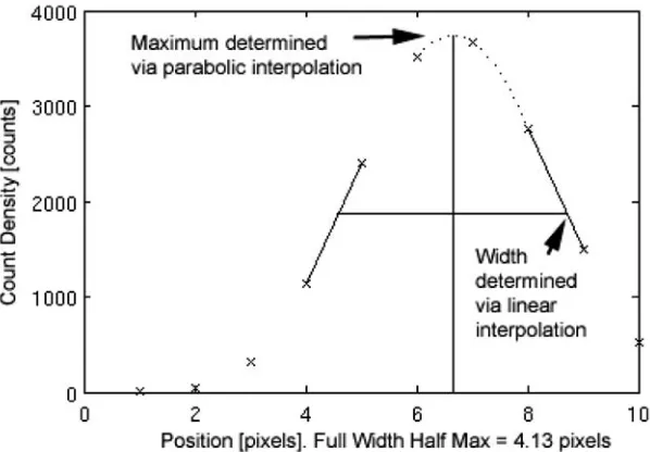
FIG. 12. Example of FWHM calculation, adapted from NEMA NU-1 2001 protocols. Given a profile through a line spread function (crosses indicate measured values), the maximum is determined via parabolic fit (dotted curve) through the largest measured value and its two nearest neighbours. The maximum interpolated value is then determined from the local maximum value of the fitted parabola. The half maximum locations are determined by linear interpolations from the nearest two neighbours of the half maximum value (see Ref. [8]).
In general, intrinsic spatial resolution improves with an increase in the number of photomultipliers for the same crystal diameter (implying a decrease in the diameter of each tube) or the energy of incoming photons and with a decrease in the thickness of the crystal or light guide, the width of PHA window, the proportion of scattered photons and the count rate. Collimator resolution improves with an increase in the number or length of holes and a decrease in the diameter of holes or thickness of septa.
The major factors that degrade intrinsic spatial resolution are electronic component failure; poor alignment of the gains of the photomultipliers; defects in, or deterioration of, the crystal and high count rate. In some cameras, switching to the high count rate mode decreases spatial resolution. System resolution is affected by the collimator used and degrades as the distance from the radiation source to the collimator surface increases.
Another major factor that affects the spatial resolution in a digital image is the sampling of the image, i.e. the number of digital picture elements or pixels. Increasing the area of the camera face corresponding to the digital image without a corresponding increase in the matrix size degrades the spatial resolution (see Table 1). This is an operational characteristic of digital systems and should not be considered a system failure.
2.1.6.2. Energy resolution
Energy resolution describes the capability of the scintillation camera to distinguish between photons of different energies, in particular between primary and scattered radiation. It is conventionally quantified as the FWHM of the photopeak, measured in energy units. This is expressed as a percentage of the gamma radiation energy (%FWHM). (Thus, a small %FWHM corresponds to good or ‘high’ energy resolution.)
The major factors that degrade energy resolution are poor alignment of the gains of the photomultipliers; failure of one or more photomultipliers; defects in, or deterioration of, the crystal; physical separation of the photomultiplier–light guide assembly from the crystal and high count rate.
2.1.6.3. Response to uniform irradiation (flood field uniformity)
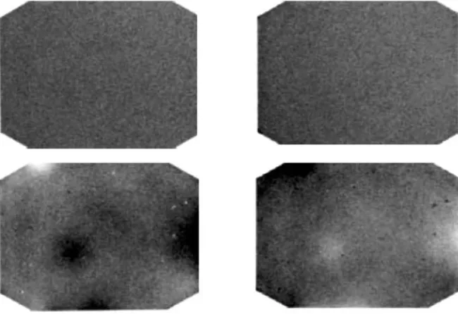
The response to uniform irradiation (flood field uniformity) is a performance characteristic of a scintillation camera that describes the degree of uniformity of count density in the image when the detector is flooded with a spatially uniform flux of incident photons (see Fig. 13). It may also describe the degree of constancy of count rate from a collimated point source when the source is moved over the field of view.
Flood field uniformity may be quantified as the degree of uniformity exhibited by the detector itself (intrinsic uniformity) or by the detector with collimator mounted (system uniformity). It may also be quantified in terms of the maximum variation in count density over the entire field of view (integral uniformity) or in terms of the maximum rate of change of count density over a specified distance (differential uniformity). (Thus, a small variation or rate of change corresponds to good or ‘high’ uniformity.)
FIG. 13. Routine intrinsic uniformity image, 99mTc, 3 million counts, 20% energy window
set symmetrically over the 140 keV photopeak of 99mTc. The image shows good
The major factors that degrade intrinsic uniformity are poor alignment of the gains of the photomultipliers; failure of one or more photomultipliers (see Fig. 14); spatial non-linearities; defects in, or deterioration of, the crystal; physical separation of the photomultiplier–light guide assembly from the crystal (see Fig. 15); incorrect setting of the position or width of the PHA window and high count rate. Additional factors that degrade system uniformity are defects in, or damage to, the collimator (see Fig. 16).
FIG. 14. Defective PMT. Daily quality control image of flood field uniformity, 99mTc,
15% energy window, 4 million counts. Results: The image shows a large, circular cold area that was due to a defective PMT. Note the inner halo of lower counts and the outer halo of higher counts at the edge of the defect. Service is required (see Ref. [3]).
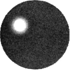
FIG. 15. Loss of optical coupling. A 2.5 million count intrinsic flood image acquired with
99mTc. Regions of altered intensity with clearly defined borders (arrows) are seen in the
For a more detailed discussion and additional image examples, refer to Section 2.2 of Ref. [3].
2.1.6.4. Spatial distortion (spatial non-linearity)
Spatial distortion is a performance characteristic of a scintillation camera that describes the amount of spatial distortion of the image with respect to the object. Spatial non-linearity describes the degree of non-linearity in the image of a linear object. Spatial non-linearity may be quantified as the maximum spatial displacement in the image over the field of view and can be estimated by inspecting the image of a linear object. (Thus, a small displacement corresponds to good or high linearity.)
Spatial distortion and flood field uniformity are closely related. If severe spatial displacements occur, the uniformity will be poor in the same areas. The major factors that degrade spatial distortion are the same as those listed for flood field uniformity.
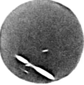
FIG. 16. System uniformity — collimator septa damage — scraped. Routine system uniformity, 99mTc flood source, 20% energy window, 3 million counts. Low energy high
2.1.6.5. Integral and differential ADC linearity
ADC linearity describes the capability of an ADC to convert accurately an analogue position signal to a digital address or location and is directly related to spatial distortion and flood field uniformity.
An ideal system should give a linear relationship between the location of an interaction in the crystal and the corresponding address in the digital image (see Fig. 17(a)). This should be true for both the X and the Y directions. Poor integral linearity in an ADC causes the relationship between distance on the camera face and distance on the digital image to vary across the image. It is difficult to detect without precise quantitative measurements.
In an ideal system, the sizes of all the bins are equal (see Fig. 17(b)). In an ADC with poor differential linearity, bin size varies in an irregular manner over the image. Poor differential linearity in an ADC causes stripes and lines to appear in the digital image. The effect is usually seen in both the X and the Y directions, i.e. both horizontal and vertical lines appear, but in some instances only one axis is affected (see Fig. 18).
The major factors that degrade integral linearity in a camera–computer system are a poorly calibrated analogue amplifier or a failure in the camera itself. Differential non-linearity may be present in an ADC as the result of faulty power supplies, which allow transients to affect the conversion process. Another possible cause of differential non-linearity is improper matching of circuits in the analogue part of the camera–computer interface.
For a more detailed discussion and additional image examples, refer to Section 5.1 of Ref. [3].