Systems Reference Library
IBM System/360 Principles of Operation
This manual is a comprehensive presentation of the characteristics, functions, and features of the IBM Sys-tem/360. The material is prescnted in a direct manner, assuming that the reader has a basic knowledge of IBM data processing systems and has read the IBM System/360 Systems Summary, Form A22-6810. The manual is useful for individual study, as an instruction aid, and as a machine reference manual.
The manual defines System/360 operating princi-ples, central processing unit, instructions, system con-trol panel, branching, status switching, interruption system, and input/output operations.
Descriptions of specific input/output devices used with System/360 appear in separate publications. Also, details unique to each model of the System/360 appear in separate publications.
IBM System/360 ... ..
General-Purpose Design ... .. Compatibility ... . System Program ... . System Alerts ... . Multisystem Operation ... . Input/Output ... . Technology ... . System Structure ... ..
Main Storage ... . Information Formats ... .
~1~;~!~~;n
p~~iti~'~i~g"::::::::::::::::::::::::::::::::::::::::::::::::::::::
Central Processing Unit ... . General Registers ... . Floating-Point Registers ... . Arithmetic and Logical Unit ... .. Fixed-Point Arithmetic ... . Decimal Arithmetic ... . Floating Point Arithmetic ... .. Logical Operations ... . Program Execution ... . Instruction Format ... . Address Generation ... . Sequential Instruction Execution ... . Branching ... . Program Status Word ... . Interruption ... . Protection Feature ... . Timer Feature ... . Direct Control Feature ... . Multisystem Feature ... . Input/Output ... . Input/Output Devices and Control Units ... .. Input/Output Interface ... . Channels ... . Input/Output Instructions ... . Input/Output Operation Initiation ... . Input/Output Commands ... . Input/Output Termination ... .. Input/Output Interruptions ... .. System Control Panel ... .
System Control Panel Functions ... ~ ... . Operation Control Section ... . Operation Intervention Section ... . Customer Engineering Section ... . Fixed-Point Arithmetic ... .
Data Format ... . Number Representation ... .
Condi~ion Code ... .. Instruction Format ... . Instructions ... . Load ... .. Load Halfword ... . Load and Test ... . Load Complement ... . Load Positive ... . Load Negative ... .. Load Multiple ... . Add ... . Add Halfword ... . Add Logical ... . Subtract ... . Subtract Halfword ... . Subtract Logical ... .
g~~~:~:
H~if~~~d"'::::::::::::::::::::::::::::::::::::::::::::::::::::::::::::
Multiply ... . Multiply Halfword ... . Divide ... . Convert to Binary ... .
Convert to Decimal ... " ... , ... .
Store ... . Store Halfword ... . Store Multiple ... . Shift Left Single ... . Shift Right Single ... . Shift Left Double ... . 5 5 5 5 6 6 6 6 7 7 7 8 8 8 9 9 9 10 10 11 11 12 12 13 15 15 15 16 18 18 18 18 19 19 19 19 19 20 20 21 21 21 21 22 22 22 23 23 23 24 24 25 25 25 25 26 26 26 26 27 27 27 28 28 28 29 29 29 30 30 30 31 31 31 31 32 32 32
Contents
Decimal Arithmetic ... 34Data Format . ' ... '.... ... ... ... 34
Number Representation ... 34
Condition Code ... , ... ,... 35
Instruction Format .... ... 35
Instructions ... , ... '... 35
Add Decimal ...•... 35
Subtract Decimal ... ... 36
Zero and Add ... 36
Compare Decimal ... '... ... 37
Multiply Decimal ... '... 37
Divide Decimal ... ,... 37
Pack ... '... 38
Unpack ... 38
Move with Offset ... ... 38
Decimal Arithmetic Exceptions ... 39
Floating-Point Arithmetic ... ... ... 40
Data Format ... 40
Number Representation ... 40
Normalization ... 41
Condition Code ... 41
Instruction Format ... 41
Instructions ... ,... 42
Load ... ,... 43
Load and Test ... 43
Load Complement ... 43
Load Positive ... 43
Load Negative ... 44
Add Normalized ... ... 44
Add U nnormalized ... ... ... 45
Subtract Normalized ... 45
Subtract Unnormalized ... 46
Compare ... 46
IIalve ... ... 47
Multiply ... 47
Divide .... ... 48
Store ... ... 49
Floating-Point Arithmetic Exceptions ... 49
Logical Operations ... ... 50
Data Format ... ... 50
Condition Code ... ... 51
Instruction Format ... 51
Instructions ... " ... '" .. . ... .. . . . ... .. . .. 52
Move ... , ... 52
Move Numerics ... 53
Move Zones ... 53
Compare Logical ... 53
AND ... 54
OR ... 54
Exclusive OR ... 55
Test Under Mask. ... 55
Insert Character .... . ... '" ... .. . 55
Store Character .... . ... ... .. 55
Load Address ... ... 56
Translate .. ... ... ... ... ... 56
Translate and Test ... ... 56
Edit ... ... 57
Edit and Mark ... ... 58
Shift Left Single . . . .. . . ... " ... , .. , .. , .. 59
Shift Right Single ... ... 59
Shift Left Double ... 59
Shift Right Double ... ... ... 60
Logical Operation Exceptions ... 60
Branching ... , ... ,... 61
Normal Sequential Operation ... 61
Sequential Operation Exceptions ... ... ... 62
Decision-Making ... ... 62
Instruction Formats ... ... ... 62
Branching Instructions .... ... 63
Branch On Condition ... 63
Branch and Link ... ... ... 64
Branch On Count ... .. ... ... 64
Branch On Index High ' ... .... ... 64
Status-Switching ... .
Program States ... . Problem State ... , ... , ... . Wait State ... . Masked States ... .. Stopped State ... .. ... . Storage Protection ... .
Area Identification ... .
Protection Action . . . ... . . . .. '" ... .
Locations Protected ... . Program Status Word ... .. ... . Multisystem Operation ... .. Direct Address Relocation ... . Malfunction Indication ... .. System Initialization ... . Instruction Format ... , ... . Instructions ... , . ... . ... . Load PS"V ... " , ... .
Set Program Mask .... .. ... .. Set System Mask . .. ... .. Supervisor Call ... _ ... . Set Storage Key ... . Insert Storage Key ... . Write Direct ... , ... . Read Direct . .. ... . ... . Diagnose ... . Status-Switching Exceptions ... . Interruptions ... . Interruption Action ... . Instruction Execution ... " ... .
Source Identification ... . Location Determination ... . Input/Output Interruption . Program Interruption ... ... .. ... .. Operation Exception ... _... .. ... .. Privileged-Operation Exception ... _ ... _ Execute Exception . .. ... . Protection Exception ... .. Addressing Exception ... _ ... _ ... . Specifica tion Exception ... . Data Exception ... . Fixed-Point-Overflow Exception . _ ... . Fixed-Po:int-Divide Exception ... . Decimal-Overflow Exception ... . Decimal-Divide Exception Exponent-Overflow Exception Exponent-Underflow Exception ... .. Significance Exception . ... ... .. ... .. Floating-Point-Divide Exception ... . Supervisor-Call Interruption .... . ... . External Interruption ... . ... . Timer ... . Interrupt Key ... .. ... .. External Signal ... . Priority of Interruptions Interruption Exceptions ... . Input/Output Operations ... .. Attachment of Input/Output Devices Input/Output Devices .... .. ... . Control Units ... . Channels ... . ... . System Operation ... .. ... . Compatibility of Operation ... .. ... .. Control of Input/Output Devices .... . Input/Output Device Addressing ... . Instruction Exception Handling ... . States of the Input/Output System Resetting of the Input/Output System Condition Code ... . Instruction Format. .. ... . Instructions .. .. .. .. .. .. .. .. . .. ... .. ~rtVO ... . Test VO ... .. Halt VO ... ... .. ... .. Test Channel ... . Execution of Input/Output Operations ... . 67 67 67 67 68 68 69 69 69 69 69 70 70 71 71 71 71 72 72 72 72 73 73 73 74 74 74 76 76 77 77 77 78 78 78 78 78 78 78 79 79 79 79 79 79 79 79 79 79 79 80 80 80 81 81 82 83 83 83 83 84 85 86 87 87 88 88 90 90 92 92 92 93 94 95 96
~~~:~~y
X~d~:s~a
w
~~~i'::::::::::::::::::::::::::::::::::::::::::::::::::::::
Channel Command Word ... . Command Code ... . Definition of Storage Area ... . Chaining .. .. ... . Skipping ... . Program-Controlled Interruption ... . Commands ... . Termination of Input/Output Operations ... . Types of Termination ... . Input/Output Interruptions ... . Channel Status Word ... . Unit Status Conditions ... .. Channel Status Conditions ... . Content of Channel Status Word ... .. System Control Panel ... ... . System Control Functions ... . System Reset ... . Store and Display ... . Initial Program Loading ... . Operator Control Section ... .. ... . Emergency Pull Switch ... . Power-On Key ... . Power-Off Key ... . ... . Interrupt Key ... . Wait Light ... . Manual Light ... . System Light ... . Test Light ... . Load Light ... . Load-Unit Switches ... . Load Key ... . Prefix-Select Key Switch ... . Operator Intervention Section ... . System-Reset Key ... .. Stop Key ... . Rate Switch ... . ... . Start Key... .. ... . Storage-Select Switch ... . Address Switches ... . Data Switches ... . Store Key ... . Display Key ... . Set IC Key ... . Address-Compare Switches ... . Alternate-Prefix Light ... .. Customer Engineering Section ... . 96 96 96 97 97 98 100 100 101 104 104 105 108 109 112 114 117 117 117 117 118 118 119 119 119 119 119 119 119 119 119 119 120 120 120 120 120 120 120 121 121 121 121 121 121 121 121 121 Appendix ... ... ... 122A. Instruction Use Examples .. ... 122
Assembly Language Examples ... ... 128
B. Fixed-Point and Two's Complement Notation ... 132
C. Floating-Point Arithmetic ... 133
D. Powers of Two Table ... .. ... 135
E. Hexadecimal-Decimal Conversion Table ... 136
F. EBCDIC and ASCII (Extended) Charts ... 141
C. Instructions . ... .. .. ... ... 142
Data Formats 142 Hexadecimal Representation ... ... 142
Instructions by Format Type ... 142
Control Word Formats ... 144
Operation Codes ... .... ... .. ... 145
Permanent Storage Assignment .. ... 147
Condition Code Setting .... ... 147
Interruption Action ... ... ... 148
Instruction Length Recording ... 148
Program Interruptions ... . ... 148
Editing ... . ... ... ... . 153
System Control Panel ... ... 153
Input/Output Operations ... ... ... ... 153
Time and Method of Creating and Storing Status Indications .. '" ... . ... 155
Functions That May Differ Among Models ... ... 156
Alphabetic List of Instructions .. ... ... 159
The IBM System/360 is a solid-state, program com-patible, data processing system providing the speed, precision, and data manipulating versatility demand-ed by the challenge of commerce, science, and in-dustry. System/360, with advanced logical design im-plemented by microminiature technology, provides a new dimension of performance, flexibility, and relia-bility. This dimension makes possible a new, more efficient systems approach to all areas of information processing, with economy of implementation and ease of use. System/360 is a single, coordinated set of new data processing components intended to replace the old logical structure with an advanced creative de-sign for present and future application.
The logical design of System/360 permits efficient use at several levels of performance with the preser-vation of upward and downward program compati-bility. Extremely high performance and reliability re-quirements are met by combining several models into one multisystem using the multisystem feature.
General-Purpose Design
System/360 is a general-purpose system designed to be tailored for commercial, scientific, communications, or control applications. A Standard instruction set pro-vides the basic computing function of the system .. To this set a decimal feature may be added to provide a
Commercial instruction set or a floating-point feature may be added to provide a Scientific instruction set. When the storage protection feature is added to the commercial and scientific features, a Universal set is obtained. Direct control and timer features may be added to satisfy requirements for TELE-PROCESSINC@ systems to allow load-sharing or to satisfy real-time needs.
System/360 can accommodate large quantities of addressable storage. The markedly increased capaci-ties over other present storage is provided by the combined use of high-speed storage of medium size and large-capacity storage of medium speed. Thus, the requirements for both performance and size are satisfied in one system by incorporating a heirarchy of storage units. The design also anticipates future development of even greater storage capacities. Sys-tem/360 incorporates a standard method for attaching input/output devices differing in function, data rate,
IBM System/360
and access time. An individual System/360 is obtained by selecting the system components most suited to the applications from a wide variety of alternatives in in-ternal performance, functional ability, and input/out-put (I/O).
Models of System/360 differ in storage speed, width (the amount of data obtained in each instruction ac-cess), register width, and capability of simultaneous processing. Yet these differences do not affect the logi-cal appearance of System/360 to the programmer. Several cpu's permit a wide choice in internal per-formance. The range is such that the ratio of internal performances between the largest and the smallest model is approximately 50 for scientific computation and 15 for commercial processing.
Compatibility
All models of System/360 are upward and downward program compatible, that is, any program gives identi-cal results on any model. Compatibility allows for ease in systems growth, convenience in systems back-up, and simplicity in education.
The compatibility rule has three limitations. 1. The systems facilities used by a program should be the same in each case. Thus, the optional CPU fea-tures and the storage capacity, as well as the quantity, type, and priority of I/O equipment, should be equiva-lent.
2. The program should be independent of the re-lation of instruction execution times and of I/O data rates, access times, and command execution times.
3. The compatibility rule does not apply to detail functions for which neither frequency of occurrence nor usefulness of result warrants identical action in all models. These functions, all explicitly identified in this manual, are concerned with the handling of in-valid programs and machine malfunctions.
System Program
efficient switching from one program to another, as well as for the relocation of programs in storage. To the prob1em programmer, the supervisory program and the equipment are indistinguishable.
System Alerts
The interruption system permits the CPU automatically to change state as a result of conditions arising out-side of the system, in 1/0 units, or in the CPU itself. Interruption switches the CPU from one program to another by changing not only the instruction address but all essential machine-status information.
A storage protection feature permits one program to be preserved when another program erroneously at-tempts to store information in the area assigned to the first program. Protection does not cause any loss of performance. Storage operations initiated from the CPU, as well as those initiated from a channel, are sub-ject to the protection procedure.
Programs are checked for correct instructions and data as they are executed. This policing-action identi-fies and separates program errors and machine errors. Thus, program errors cannot create machine checks since each type of error causes a unique interruption. In addition to an interruption due to machine mal-function, the information necessary to identify the error is recorded automatically in a predetermined storage location. This procedure appreciably reduces the mean-time to repair a machine fault. Moreover, operator errors are reduced by minimizing the active manual controls. To reduce accidental operator errors, operator consoles are 110 devices and function under control of the system program.
Multisystem Operation
Several models of System/360 can be combined into one multisystem configuration. Three levels of com-munication between CPu's are available. Largest in ca-pacity, and moderately fast in response, is communi-cations by means of shared 1/0 device, for example,
a disk file. Faster transmission is obtained by direct connection between the channels of two individual systems. Finally, storage may be shared on some models between two cpu's, making information ex-change possible at storage speeds. These modes of communication are supplemented by allowing one CPU to be interrupted by another CPU and by making direct status information available from one CPU to another.
Input/Output
Channels provide the data path and control for 1/0 devices as they communicate with the CPU. In general, channels operate asynchronously with the CPU and, in some cases, a single data path is made up of several sub channels. When this is the case, the single data path is shared by several low-speed devices, for ex-ample, card readers, punches, printers, and terminals. This channel is called a multiplexor channel. Chan-nels that are not made up of several such subchanChan-nels can operate at higher speed than the multiplexor channels and are called selector channels. In every case, the amount of data that comes into the channel in parallel from an 110 device is a byte. All channels or subchannels operate the same and respond to the same 110 instructions and commands.
Each 110 device is connected to one or more chan-nels by an 110 interface. This 110 interface allows at-tachment of present and future 110 devices without altering the instruction set or channel function. Con-trol units are used where necessary to match the in-ternal connections of the 110 device to the interface. Flexibility is enhanced by optional access to a control unit or dcvice from either of two channels.
Technology
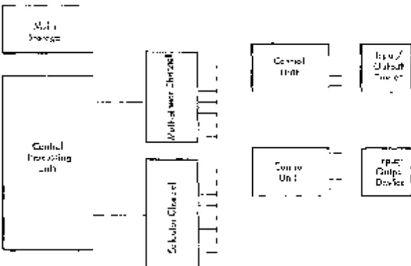
The basic structure of a System/360 consists of main storage, a central processing unit (cPu), the selector and multiplexor channels, and the input! output de-vices attached to the channels through control units.
It is possible for systems to communicate with each other by means of shared I/O devices, a channel, or shared storage. Figure 1 shows the basic organization of a single system.
Main Storage
Storage units may be either physically integrated with the CPU or constructed as stand-alone units. The stor-age cycle is not directly related to the internal cycling of the CPU, thus permitting selection of optimum stor-age speed for a given word size. The physical differ-ences in the various main-storage units do not affect the logical structure of the system.
Fetching and storing of data by the CPU are not af-fected by any concurrent I/O data transfer. If an I/O operation refers to the same storage location as the CPU operation, the accesses are granted in the se-quence in which they are requested. If the first refer-ence changes the contents of the location, any sub-sequent storage fetches obtain the new contents. Con-current I/O and CPU references to the same storage location never cause a machine-check indication.
Main Storage
-Control'--System Structure
Information Formats
The system transmits information between main stor-age and the CPU in units of eight bits, or a multiple of eight bits at a time. An eight-bit unit of information is called a byte, the basic building block of all formats. A ninth bit, the parity or check bit, is transmitted with each byte and carries parity on the bytes. The parity bit cannot be affected by the program; its only effect is to cause an interruption when a parity error is detected. References to the size of data fields and registers, therefore, exclude the associated parity bits. All storage capacities are expressed in number of bytes provided, regardless of the physical word size actually used.
Bytes may be handled separately or grouped to-gether in fields. A halfword is a group of two consecu-tive bytes and is the basic building block of instruc-tions. A word is a group of four consecutive bytes; a double word is a field consisting of two words (Figure 2). The location of any field or group of bytes is spe-cified by the address of its leftmost byte.
The length of fields is either implied by the oper-ation to be performed or stated explicitly as part of the instruction. When the length is implied, the in-formation is said to have a fixed length, which can be either one, two, four, or eight bytes.
When the length of a field is not implied by the
Input/
I
1
c - OutputUnit c
f---t - Device
....c: U
f---t
c--.... ~ f---i Q)
1
f---t""5 f---i
::E f----i Central
Processing t - Input/
Unit Control t--I - - Output
f---\ Unit t - Device
W c
f---t
t--C
c f---t ....c: U
- - I
....
.8 u - - I
Q)
- - I
W
Vl - - I
operation code, but is stated explicitly, the informa-tion is said to have variable field length. Variable-length operands are variable in Variable-length by increments of one byte.
Within any program format or any fixed-length op-erand format, the bits making up the format are con-secutively numbered from left to right starting with the number O.
Byte
Halfword
11 0 0 1 Jo 0 0 1 11 0 1 0 KO 0 1 01
15
Word
11 0 0 011 0 0 111 0 0 0 BO 0 1 011 0 0 1'1> 1 0 011 1 1
~
0 1 1116 24 31
Figure 2. Sample Information Formats
Addressing
Byte locations in storage are consecutively numbered starting with 0; each number is considered the ad-dress of the corresponding byte. A group of bytes in storage is addressed by the leftmost byte of the group. The addressing capability permits a maximum of 16,777,216 bytes, using a 24-bit binary address. This set of main-storage addresses includes some locations reserved for special purposes.
Storage addressing wraps around from the maximum byte address, 16,777,215, to address O. Variable-length operands may be located partially in the last and par-tially in the first location of storage, and are processed without any special indication.
When only a part of the maximum storage capacity is available in a given installation, the available stor-age is normally contiguously addressable, starting at address O. An addressing exception is recognized when any part of an operand is located beyond the maximum available capacity of an installation.
In some models main storage may be shared by more than one CPU. In that case, the address of a byte location is normally the same for each CPU.
Informatic)n Positioning
Fixed-length fields, such as halfwords and double words, must be located in main storage on an integral boundary for that unit of information. A boundary is called integral for a unit of information when its
stor-age address is a multiple of the length of the unit in bytes. For example, words (four bytes) must be lo-cated in storage so that their address is a multiple of the number 4. A halfword (two bytes) must have an address that is a multiple of the number 2, and double words (eight bytes) must have an address that is a multiple of the number 8.
Storage addresses are expressed in binary form. In binary, integral boundaries for halfwords, words, and double words can be specified only by the binary ad-dresses in which one, two, or three of the low-order bits, respectively, are zero. (Figure 3). For example, the integral boundary for a word is a binary address in which the two low-order positions are zero.
Varia ble fields are not limited to integral bounda-ries' but may start on any byte location.
Binary 0000 0001 0010 0011 0100 01Ql 0110 0111 1000 1001 1010
Address
Byte Byte Byte Byte Byte Byte Byte Byte Byte Byte Byte
Halfword Halfword Halfword Halfword Halfword
,
l
Word Word Word
- (
Double-Word Double-Word
Figure 3. Integral Boundaries for Halfwords, Words, and Doublewords
Central
Processing
Unit
)
l
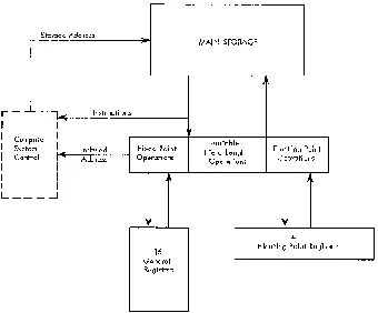
The central processing unit (Figure 4) contains the facilities for addressing main storage, for fetching or storing information, for arithmetic and logical proc-essing of data, for sequencing instructions in the de-sired order, and for initiating the communication be-tween storage and external devices.
The system control section provides the normal CPU control that guides the CPU through the operation necessary to execute the instructions. While the physical make-up of the control section in the various models of the Systems/360 may be different, the logical function remains the same.
The CPU provides 16 general registers for fixed-point operands and four floating-point registers for floating-point operands. Implementation of these registers may be in active elements, in a local storage unit, or in a separate area of main storage. In each case, the ad-dress and functions of these registers are identical.
,
Storage Address
r -
-'- -lOll(
I
IInstructions
I Co mputer I
I Sys tem I
I ~
Co ntrol
,
... Indexed AddressI I
I I
I I
L_ _ _ .-J
Fixed Point Operations
MAIN STORAGE
Variable Field Length
Operations J
Floating Point Operations
4
16
General Registers
I
Floating Point RegistersFigure 4. Central Processing Unit
General Registers
The CPU can address information in 16 general ters. The general registers can be used as index regis-ters, in address arithmetic and indexing, and as ac-cumulators in fixed-point arithmetic and logical oper-ations. The registers have a capacity of one word (32 bits). The general registers are identified by numbers 0-15 and are selected by a four-bit field in the in-struction called the R field (Figure 5).
R Field Reg No. General Registers Floating Point Registers 0000 0 !i±32 Bits. hi:"":.'::::"': 64 Bits :::':":::::::::::::::;1I!l:1 0001 1
0010 2 0011 3 0100 4 0101 5
0110 6 ... ,,' .. ··· .. ·'·:1
0111 7
1000 8 1001 9
1010 10 1011 11 1100 12 1101 13 1110 14 1111 15
Figure 5. General and Floating-Point Registers
For some operations, two adjacent registers can be coupled together, providing a two-word capacity. In these operations, the addressed register contains the high-order operand bits and must have an even address, while the implied register, containing the low-order operand bits, has the next higher address.
Floating-Point Registers
Four point registers are available for floating-point operations. These registers are two words (64 bits) in length and can contain either a short (one word) or a long (two word) floating-point operand. A short operand occupies the high-order bits of a floating-point register. The low-order portion of the register is ignored and remains unchanged in short-precision arithmetic. The floating-point registers are identified by the numbers 0, 2, 4, and 6 (Figure 5). The operation code determines which type of register is to be used in an operation.
Arithmetic and Logical Unit
parallel or in series; the width of the arithmetic unit, the multiplicity of the shifting paths, and the degree of simultaneity in performing the different types of arithmetic differ from one CPU to another without af-fecting the logical appearance of the design.
Arithmetic and logical operations performed by the CPU fall into four classes: fixed-point arithmetic, deci-mal arithmetic, floating-point arithmetic, and logical operations. These classes differ in the data formats used, the registers involved, the operations provided, and the way the field length is stated.
Fixed-Point Arithmetic
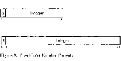
The basic arithmetic operand is the 32-bit fixed-point binary word. Sixteen-bit halfword operands may be specified in most operations for improved performancc or storage utilization. See Figure 6. To preserve precision, some products and all dividends are 64 bits long.
Integer
o 1 15
Integer
o 1 31
Figure 6. Fixed-Point Number Formats
Because the 32-bit word size conveniently accom-modates a 24-bit address, fixed-point arithmetic can be used both for integer operand arithmetic and for address arithmetic. This combined usage provides economy and permits the entire fixed-point instruction set and several logical operations to be used in ad-dress computation. Thus, multiplication, shifting, and logical manipulation of address components are pos-sible.
The absence of recomplementation and the ease of extension and truncation make two's-complement no-tation desirable for address components and fixed-point operands. Since integer and addressing algorisms often require repeated reference to operands or inter-mediate results, the use of multiple registers is advan-tageous in arithmetic sequences and address calcula-tions.
Additions, subtractions, multiplications, divisions, and comparisons are performed upon one operand in a register and another operand either in a register or from storage. Multiple-precision operation is made convenient by the two's-complement notation and by recognition of the carry from one word to another. A
word in one register or a double word in a pair of adjacent registers may be shifted left or right. A pair of conversion instructions - CONVERT TO BINARY and CONVERT TO DECIMAL - provides transition between decimal and binary radix (number base) without the use of tables. Multiple-register loading and storing in-structions facilitate subroutine switching.
Decimal Arithmetic
Decimal arithmetic is designed for processes requiring few computational steps between the source input and the documented output. This type of processing is frequently found in commercial applications, par-ticularly when use is made of problem-oriented lan-guages. Because of the limited number of arithmetic operations performed on each item of data, radix con-version from decimal to binary and back to decimal is not justified, and the use of registers for intermedi-ate results yields no advantage over storage-to-storage processing. Hence, decimal arithmetic is provided, and both operands and results are located in storage. Decimal arithmetic includes addition, subtraction, multiplication, division, and comparison.
Decimal numbers are treated as signed integers with a variable-field-length format from one to 16" bytes long. Negative numbers are carried in true form.
The decimal digits 0-9 are represented in the four-bit binary-cod ed-decimal form by 0000-1001, respec-tively. The codes 1010-1111 are not valid as digits and are reserved for sign codes; 1011 and 1101 represent a minus; the other four codes are interpreted as plus. The sign codes generated in decimal arithmetic de-pend upon the character set preferred (Figure 7). When the expanded binary coded decimal interchange code (EBCDIC) is preferred, the codes are 1100 and 1101. When the ASCII set, expanded to eight bits, is preferred, the codes are 1010 and 1011. The choice between the two code sets is determined by a mode bit.
Decimal operands are represented by four-bit bin-ary-coded-decimal digits packed two to a byte. They appear in fields of variable length and are accompa-nied by a sign in the rightmost four bits of the low-Digit Code Sign Code
0 0000 + 1010
1 0001
-
10112 0010 + 1100
3 0011
-
11014 0100 + 1110
5 0101 + 1111
6 0110 7 0111
8 1000
9 1001
order byte. Operand fields may be located on any byte boundary, and may have length up to 31 digits and sign. Operands participating in an operation have independent lengths. Packing of digits within a byte (Figure 8) and of variable-length fields within stor-age results in efficient use of storstor-age, in increased arithmetic performance, and in an improved rate of data transmission between storage and files.
I Digit I Digit I Digit
[~~ ~-J
Digit I Digit I Digit I Digit I SignI
I
ZoneI
DigitI
ZoneC-_-
~~]
DigitI
ZoneI
DigitI
SignI
DigitI
Figure 8. Packed and Zoned Decimal Number FormatsDecimal numbers may also appear in a zoned for-mat as a subset of the eight-bit alphameric character set (Figure 8). This representation is required for character-set sensitive I/O devices. The zoned format is not used in decimal arithmetic operations. Instruc-tions are provided for packing and unpacking decimal numbers so that they may be changed from the zoned to the packed format and vice versa.
Floating-Point Arithmetic
Floating-point numbers occur in either of two fixed-length formats - short or long. These formats differ only in the length of the fractions (Figure 9).
Short Floating-Point Number
IS I
CharacteristicI
Fractiono I 7 8 31
Long Floating-Point Number
~IS~I_C_h_a_r_ac_t_e_ri_st_ic~I
_________ F_ra_c_ti_o_n ______~~~~
______~
o 1 78 63
Figure 9. Short and Long Floating-Point Number Formats
Operands are either 32 or 64 bits long. The short length, equivalent to seven decimal places of pre-cision, permits a maximum number of operands to be placed in storage and gives the shortest execution times. The long length, used when higher precision is desired, gives up to 17 decimal places of precision, thus eliminating most requirements for double-pre-cision arithmetic.
The operand lengths, being powers of two, permit maximum efficiency in the use of binary addressing and in matching the phys,ical word sizes of storage. Floating-point arithmetic is designed to allow easy transition between the two formats.
The fraction of a floating-point number is expressed in hexadecimal ( base 16) digits, each consisting of four binary bits and having the values 0-15. In the short format, the fraction consists of six hexadecimal digits occupying bits 8-31. In the long format the fraction has 14 hexadecimal digits occupying bits 8-63. The radix point of the fraction is assumed to be im-mediately to the left of the high-order fraction digit. To provide the proper magnitude for the floating-point number, the fraction is considered to be mul-tiplied by a power of 16. The characteristic portion, bits 1-7 of both formats, is used to indicate this power. The characteristic is treated as an excess 64 number with a range from -64 through +63, and permits representation of decimal numbers with magnitudes in the range of 10-78 to 1075•
Bit position 0 in either format is the sign (S) of the fraction. The fraction of negative numbers is carried in true form.
Four 64-bit floating-point registers are provided. Arithmetic operations are performed with one oper-and in a register oper-and another either in a .register or from storage. The result, developed in a register, is generally of the same length as the operands. The availability of several floating-point registers elimi-nates much storing and loading of intermediate re-sults.
Logical Operations
Logical information is handled as fixed-length and variable-length data. It is subject to such operations as comparison, translation, editing, bit testing, and bit setting.
When used as a fixed-length operand, logical in-formation can consist of either one, four, or eight bytes and is processed in the general registers.
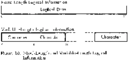
A large portion of logical information consists of alphabetic or numeric character codes, called alpha-meric data, and is used for communication with char-acter-set sensitive I/O devices. This information has the variable-field-Iength format and can consist of up to 256 bytes (Figure 10). It is processed in storage, left to right, an eight-bit byte at a time.
Fixed Lengl'h Logical Information
I
Logical DataVariable-Length Logical Information
I
CharacterI
CharacterI-~~
16
~~]
CharacterFigure 10. Fixed-Length and Variable-Length Logical Information
31
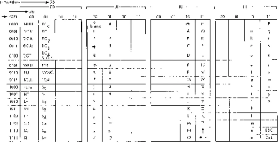
( EBCDIC) (Figure 11) or the American Standard Code for Information Interchange (ASCII) extcnded to eight bits (Figure 12).
The preferred codes do not have a graphic defined for all 256 eight-bit codes. When it is desirable to rep-resent all possible bit patterns, a hexadecimal repre-sentation may be used instead of the preferred eight-bit code. The hexadecimal representation uses one graphic for a four-bit code, and therefore, two graph-ics for an eight-bit byte. The graphgraph-ics 0-9 are used for codes 0000-1001; the graphics A-F are used for
codes 1010-1111.
Bit Positions - , - - - - . .. 01
L
U:-
2- 3 - - 00 - - - , 4567 00 01 10 11~---01---~
00 01 10 11
0000 NUL BLANK &
-0001 /
0010 0011
0100 PF RES BYP PN
0101 HT NL LF RS
0110 LC .BS EOB UC
-0111 DEL IDL PRE EOT
1000
--1001 , "
1010 ? ! :
1011 $ , #
1100 4--- * % @
1101 ( ) ry-.. I
1110 + ; - =
1111 $ C7 + j
-Figure 11. Extended Binary-Coded-Decimal Interchange Code
Program Execution
The CPU program consists of instructions, index words, and control words specifying the operations to be per-formed. This information resides in main storage and general registers, and may be operated upon as data.
Instruction Format
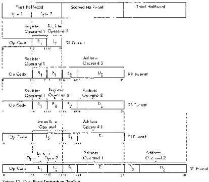
The length of an instruction format can be one, two, or three halfwords. It is related to the number of stor-age addresses necessary for the operation. An instruc-tion consisting of only one halfword causes no refer-ence to main storage. A two-halfword instruction pro-vides one storage-address specification; a three-half-word instruction provides two storage-address specifi-cations. All instructions must be located in storage on integral boundaries for halfwords. Figure 13 shows five basic instruction formats.
The five basic instruction formats are denoted by the format codes RR, RX, RS, SI, and ss. The format codes express, in general terms, the operation to be performed. RR denotes a register-to-register operation; RX, a register-to-indexed-storage operation; RS, a
regis-~---10---~ ~---11---,
00 01 10 11 00 01 10 11
> < :j: 0
a i A J 1
b k s B K S 2
c I t C L T 3
d m u D M U 4
e n v E N V 5
f 0 w F 0 W 6
9 P x G P X 7
h q y H Q Y 8
i r z I R Z 9
_._---Bit Positions - - - -•• 76
L
I • X5 0 0 - - - , 4321 00 01 10 1101
00 01 10 11 00 01 10
. . - - - - 1 0 - - - . 1 '--1 - - - - 1 1 - - - . 11 00 01 10 11
~-~-~-~----~
0000 NULL DCa blank b a (a) P
0001 50M DC 1
- - - , - - - --- -
r----A- ---
---Q a q
0010 EOA DC 2 0011 EOM DC
3
2
41= 3
-B R
C 5
b r
I - - - + - - - - t - - - f
---C S
- - 1---+----+ ----~
0100 EOT DC4
5TOP $ 4 D T d t
0101 WRU ERR % 5 E U e u
- - - ---- --- 1---- -- - - - f - - - f - - - - J - - - j
0110 RU 5YNC & 6 F V v
0111 BELL LEM - -
,---"- ~
~---,
7 -f---G W
---- - -- -
---9 W
1000 BK5P 50 1001 HT 51
8 9
H X
f
-I Y
f
-~--+--_+--T_-~
h x
---- 1----:- --
-I Y
- I-- - --~ - - - f - - - , ~
1010 LF 52 J Z i z
r +__j
-1011 VT 53 + K [ k
r---r--+---~--__j
1100 FF 54 ~
-~--
-L
"
--~r--·--r---+--1--1101 CR 55 M ::J m
1110 50 56 N
f
r--- r- - -f- - - -n - - -E5C1 - - - r- -- ----1---- I
---1111 51 57 / ? 0 4-- o DEL
Figure 12. Eight-Bit Representation for American Standard Code for Information Interchange for Use in Eight-Bit Environment
ter-to-storage operation; SI, a storage and immediate-operand operation; and SS, a storage-to-storage oper-ation.
For purposes of describing the execution of instruc-tions, operands are designated as first and second op-erands and, in the case of BRANCH ON INDEX, third op-erands. These names refer to the manner in which the operands participate. The operand to which a field in an instruction format applies is generally denoted by the number following the code name of the field, for example, Rl, Bl, L2, D2 •
In each format, the first instruction halfword con-sists of two parts. The first byte contains the oper-ation code (op code). The length and format of an instruction are specified by the first two bits of the operation code.
INSTRUCTION LENGTH RECORDING
BIT POSITIONS INSTRUCTION INSTRUCTION
<0-1) LENGTH FORMAT
00 One halfword RR
01 Two halfwords RX
10 Two halfwords RS or SI
11 Three halfwords SS
The second byte is used either as two 4-bit fields or as a single eight-bit field. This byte can contain the following information:
Four-bit operand register specification Rb R2, or
R3 )
Four-bit index register specification (X2 ) Four-bit mask (M1 )
Four-bit operand length specification (Ll or L2 )
Eight-bit operand length specification (L) Eight-bit byte of immediate data (12 )
In some instructions a four-bit field or the whole sec-ond byte of the first halfword is ignored.
The second and third halfwords always have the same format:
Four-bit base register designator (Bl or B2 ), fol-lowed by a 12-bit displacement (Dl or D2)'
Address Generation
in-L -____ F_ir_s.t __
H_aTf_w_o_rd
______ - ; ____ s_ec_o_n_d __H_a_f_W_O_rd
________~----Th-i_rd--H_a_lf~
r Byte' Byte 2
~
I
:0
1
I
I
I
10
I
I
Register Register Operand' Operand 2
~
Op Code
I
R 1I
R2I
RR Format7 8 11 12 15 1
Register Operand'
~
Op Code
I
R,I
X, B27 8 11 12 1516
I
I I
Register Register Operand' Operand 3
r---' ..---A---y
7 8
I
11 12
Immediate
Ope~and
Op Code 12
1516 I
78 1516
I 1
I I
1920
1920
1920
Address Operand 2
"
D2
31
Address
Oper~ _ _ _ _
Address Oper?nd 1
31
31 1
I I
RX Format
RS Format
SI Format
I Length I Address Address
Op~
____----O-p_e-ra~An-d--'---~~----
__O--p-e~r?-n-d-2---~
SS Format Op Code
I
L,I
L2I
B, D,7 8 11 12 15 16 1920 - - - . - 3 1 - ' - - - 1 - - - ' 4 7
Figure 13. Five Basic Instruction Formats
struction stream in main storage, and operands lo-cated in the general or floating-point registers.
To permit the ready relocation of program seg-ments and to provide for the flexible specifications of input, output, and working areas, all instructions re-ferring to main storage have been given the capacity of employing a full address.
The address used to refer to main storage is gen-erated from the following three binary numbers:
Base Address (B) is a 24-bit number contained in a general register specified by the program in the B field of the instruction. The B field is included in every address specification. The base address can be used as a means of static relocation of programs and data. In array-type calculations, it can specify the lo-cation of an array and, in record-type processing, it can identify the record. The base address provides for addressing the entire main storage. The base address may also be used for indexing purposes.
Index (X) is a 24-bit number contained in a general register specified by the program in the X field of the instruction. It is included only in the address
speci-fied by the RX instruction format. The index can be
used to provide the address of an element within an array. Thus, the RX format instructions permit double indexing.
Displacement (D) is a 12-bit number contained in the instruction format. It is included in every address computation. The displacement provides for relative addressing up to 4095 bytes beyond the element or base address. In array-type calculations the displace-ment can be used to specify one of many items as-sociated with an element. In the processing of records, the displacement can be used to identify items within a record.
The program may have zeros in the base address, index, or displacement fields. A zero is used to indi-cate the absence of the corresponding address com-ponent. A base or index of zero implies that a zero quantity is to be used in forming the address, regard-less of the contents of general register O. A displace-ment of zero has no special significance. Initialization, modification, and testing of base addresses and in-dexes can be carried out by fixed-point instructions, or by BRANCH AND LINK, BRANCH ON COUNT, or BRANCH ON INDEX instructions.
As an aid in describing the logic of the instruction format, examples of two instructions and their related instruction formats follow.
RR Format
I
Add 7 9o 78 1112 15
Execution of the ADD instruction adds the contents of general register 9 to the contents of general register 7 and the sum of the addition is placed in general register 7.
RX Format
Store 3 10 14 300
7 8 11 1 2 15 16 1 9 20 31
Execution of the STORE instruction stores the contents of general register 3 at a main-storage location ad-dressed by the sum of 300 and the low-order 24 bits of general registers 14 and 10.
Sequential Instruction Execution
Normally, the operation of the CPU is controlled by instructions taken in sequence. An instruction is fetched from a location specified by the current struction address. The instruction address is then in-creased by the number of bytes in the instruction to address the next instruction in sequence. The instruc-tion is then executed and the same steps are repeated using the new value of the instruction address.
Conceptually, all halfwords of an instruction are fetched from storage after the preceding operation is completed and before execution of the current oper-ation, even though physical storage word size and overlap of instruction execution with storage access may cause actual instruction fetching to be different. Thus, it is possible to modify an instruction in storage by the immediately preceding instruction.
A change from sequential operation may be caused by branching, status switching, interruptions, or man-ual intervention.
Branching
The normal sequence of instructions is changed when reference is made to a subroutine, when a two-way choice is encountered, or when a segment of coding, such as a loop, is to be repeated. All these tasks can be accomplished with branching instructions.
Subroutine linkage permits not only the intro-duction of a new instruction address but also the pres-ervation of the return address and associated informa-tion.
Decision-making is generally and symmetrically provided by the BRANCH ON CONDITION instruction. This instruction inspects a two-bit condition code that reflects the result of a majority of the arithmetic, logi-cal, and I/O operations. Each of these operations can set the code in anyone of four states, and the con-ditional branch can specify any selection of these four states as the criterion for branching. For example, the condition code reflects such conditions as nonzero, first operand high, equal, overflow, channel busy, zero, etc. Once set, the condition code remains unchanged until modified by an instruction that reflects a dif-ferent condition code.
The two bits of the condition code provide for four possible condition code settings: 0, 1, 2, and 3. The specific meaning of any setting is significant only to the operation setting the condition code.
Loop control can be performed by the conditional branch when it tests the outcome of address arith-metic and counting operations. For some particularly frequent combinations of arithmetic and tests, the in-structions BRANCH ON COUNT and BRANCH ON INDEX are provided. These branches, being specialized, provide increased performance for these tasks.
Program Status Word
0-7 System mask
o Multiplexor channel mask 1 Selector c:hannel 1 mask 2 Selector c:hannel 2 mask 3 Selector channel 3 mask 4 Selector c:hannel 4 mask 5 Selector c:hannel 5 mask 6 Selector c:hannel 6 mask 7 External mask 8-11 Protection key
12 ASCII mode (A) 13 Machine check mask (M)
14 Wait state (W) 15 Problem state (P) 16-31 Interruption code 32-33 Instruction Length code (ILC) 34-35 Condition code (CC) 36-39 Program mask
36 Fixed-point overflow mask 37 Decimal overflow mask 38 Exponent underflow mask 39 Significance mask 40-63 Instruction address
Figure 14. Program Status Word Format
Interrupti~.n
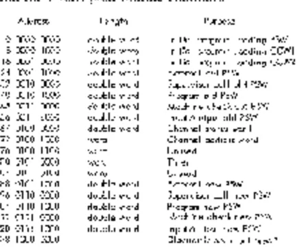
The interruption system permits the CPU to change state as a result of conditions external to the system, in input/output (I/O) units or in the CPU itself. Five classes of interruption conditions are possible: I/O, program, supervisor call, external, and machine check. Each class has two related psw's called "old" and "new" in unique main-storage locations (Figure 15). In all classes, an interruption involves merely storing the current psw in its "old" position and making the psw at the "new" position the current psw. The "old" psw holds all necessary status information of the sys-tem existing at the time of the interruption. If, at the conclusion of the interruption routine, there is an in-struction to make the old psw the current psw, the system is lrestored to the state prior to the interruption and the interrupted routine continues.
Address length Purpose
o 0000 0000 double word Initial program loading PSW 8 0000 1000 double word Initial program loading CCWI 16 0001 0000 double word Initial program loading CCW2 24 0001 1000 double word External old PSW
32 0010 0000 double word Supervisor call old PSW 40 0010 1000 double word Program old PSW 48 0011 0000 double word Machine check old PSW 56 0011 1000 double word Input/output old PSW 64 0100 0000 double word Channel status word 72 0100 1000 word Channel address word 76 0100 1100 word Unused
80 0101 0000 word Timer 84 0101 0100 word Unused 88 0101 1000 double word External new PSW 96 0110 0000 double word Supervisor call new PSW 1 04 011 a 1000 double word Program new PSW 112 0111 0000 double word Machine check new PSW 120 0111 1000 double word Input/output new PSW 128 1000 0000 Diagnostic scan-out area *
* The size of j,he diagnostic scan-out area depends upon the particular system's CPU and I/O channels.
Figure 15. Permanent Storage Assignments
Interruptions are taken only when the CPU is inter-ruptable for the interruption source. The system mask, program mask, and machine check mask bits in the psw may be used to mask certain interruptions. When masked off, an interruption either remains pending or is ignored. The system mask may keep I/O and ex-ternal interruptions pending, the program mask may cause four of the 15 program interruptions to be ig-nored, and the machine-check mask may cause ma-chine-check interruptions to be ignored. Other inter-ruptions cannot be masked off.
An interruption always takes place after one struction execution is finished and before a new in-struction execution is started. However, the occurence of an interruption may affect the execution of the cur-rent instruction. To permit proper programmed action following an interruption, the cause of the interrupt-ion is identified and provisinterrupt-ion is made to locate the last executed instruction.
Input /OutPIJt Interruption
An I/O interruption provides a means by which the CPU responds to conditions in the channels and I/O units.
An I/O interruption can occur only when the related channel is not masked. The address of the channel and I/O unit involved are recorded in the old psw. Further information concerning the I/O action is pre-served in the channel status word (csw) that is stored during the interruption.
Program Interruption
Unusual conditions encountered in a program create program interruptions. These conditions include in-correct operands and operand specifications, as well as exceptional results. The interruption code identifies the interruption cause. Figure 16 shows the different causes that may occur.
Interruption Program Interrupti on
Code Cause
1 00000001 Operation
2 00000010 Privileged operation
3 00000011 Execute
4 00000100 Protection
5 00000101 Addressing
6 00000110 Specification
7 00000111 Date
8 00001000 Fixed-point overflow
9 00001001 Fixed-point divide 10 00001010 Decimal overflow 11 0000101 I Decimal divide 12 00001100 Exponent overflow 13 000011 01 Exponent underflow 14 00001 110 Significance
15 00001111 Floating-point divide
Supervisor-Call Interruption
This interruption occurs as a result of execution of the instruction SUPERVISOR CALL. Eight bits from the in-struction format are placed in the interruption code of the old psw, permitting a message to be associated with the interruptions. A major use for the instruction SUPERVISOR CALL is to switch from the problem-state to the supervisor state. This interruption may also be used for other modes of status-switching.
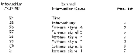
External Interruption
The external interruption provides the means by which the CPU responds to signals from the interrup-tion key on the system control panel, the timer, and the external signals of the direct control feature (Figure 17).
Interruption External
Code Bit I nterrupti on Cause Mask Bit
24 Timer
25 Interrupt key 7
26 External signal 6 7
27 External signal 5 7
28 External signal 4 7
29 External signal 3 7
30 External signal 2 7
3'1 External signal 1 7
Figure 17. Interruption Code for External Interruption
An external interruption can occur only when the system mask bit 7 is one.
The source of the interruption is identified by the interruption code in bits 24-31 of the psw. Bits 16-23 of the interruption code are made zero.
Machine-Check Interruption
The occurence of a machine check (if not masked off) terminates the current instruction, initiates a diag-nostic procedure, and subsequently causes the ma-chine-check interruption. A machine check cannot be caused by invalid data or instructions. The diagnostic scan is performed into the scan area starting at lo-cation 128. Proper execution of these steps depends on the nature of the machine check.
Priority of Interruptions
During execution of an instruction, several interrup-tion requests may occur simultaneously. Simultaneous interruption requests are honored in the following pre-determined order:
Machine Check
Program or Supervisor Call External
Input/Output
The program and supervisor-call interruptions are
mutually exclusive and cannot occur at the same time. When more than one interruption cause requests service, the action consists of storing the old psw and fetching the new psw belonging to the interruption which is taken first. This new psw subsequently is stored without any instruction execution and the next interruption psw is fetched. This process continues until no more interruptions are to be serviced. When the last interruption request has been serviced, in-struction execution is resumed using the psw last fetched. The order of execution of the interruption subroutines is, therefore, the reverse of the order in which the psw's are fetched.
Thus, the most important interruptions - I/O, ex-ternal, program or supervisor call - are actually serv-iced first. Machine check, when it occurs, does not al-low any other interruptions to be taken.
Program States
Over-all CPU status is determined by four types of pro-gram-state alternatives, each of which can be changed independently to its opposite and most of which are indicated by a bit or bits in the psw. The program-state alternatives are named stopped or operating, running or waiting, masked or interruptable, and sup-ervisor or problem state. These states differ in the way they affect the CPU functions and the manner in which their status is indicated and switched. All program states are independent of each other in their functions, indication, and status-switching.
Stopped or Operating States: The stopped state is entered and left by manual procedure. Instructions are not executed, interruptions are not accepted, and the timer is not updated. In the operating state, the CPU is capable of executing instructions and being inter-rupted.
Running or Waiting State: In the running state, in-struction fetching execution proceeds in the normal manner. The wait state is normally entered by the program to await an interruption, for example, an I/O interruption or operator intervention from the console. In the wait state, no instructions are processed, the timer is updated, and 110 and external interruptions are accepted, unless masked. Running or waiting state is determined by the setting of bit 14 in the psw.
Supervisor or Problem State: In the problem state, all 110 instructions and a group of control instructions are invalid. In the supervisor state, all instructions are valid. The choice of problem or supervisor state is determined by bit 15 of the psw.
Protection feature
The Protection Feature protects the contents of cer-tain areas of storage from destruction due to errone-ous storing of information during the execution of a program. This protection is achieved by identifying blocks of storage with a storage key and comparing this key with a protection key supplied with the data to be stored. The detection of a mismatch results in a protection interruption.
For protection purposes, main storage is divided in-to blocks of 2,048 bytes. A four-bit sin-torage key is as-sociated with each block. When data are stored in a storage block, the storage key is compared with the protection key. When storing is specified by an in-struction, the protection key of the current psw is used as the comparand. When storing is specified by a channel operation, a protection key supplied by the channel iis used as the comparand. The keys are said to match when they are equal or when either one is zero.
The storage key is not part of addressable storage. The key is changed by SET STORAGE KEY and is in-spected by INSERT STORAGE KEY. The protection key in the psw occupies bits 8-11 of that control word. The protection key of a channel is recorded in bits 0-3 of the csw, which is stored as a result of the channel operation. When a protection mismatch due to an in-struction is detected, the execution of this inin-struction is suppressed or terminated, and the program execu-tion is altered by an interrupexecu-tion. The protected stor-age location always remains unchanged. Protection mismatch due to an 110 operation causes the data transmission to be terminated in such a way that the protected storage location remains unchanged. The mismatch is indicated in the csw stored as a result of the operation.
Timer
f'eatureThe timer is provided as an interval timer and may be programmed to maintain the time of day. The timer consists of a full word in main storage location 80. The timer word is counted down at a rate of 50 or 60 cycles per second, depending on line frequency. The timer word is treated as a signed integer follow-ing the rules of fixed-point arithmetic. An external in-terruption condition is signaled when the value of the
timer word goes from positive to negative. The full cycle time of the timer is 15.5 hours.
An updated timer value is available at the end of each instruction execution but is not updated in the stopped state. The timer is changed by addressing storage location 80. As an interval timer, the timer is used to measure elapsed time over relatively short in-tervals. It can be set to any value at any time.
Direct
Control
featureThe direct control feature provides two instructions, READ DIRECT and WRITE DIRECT, and six external inter-ruption lines. The read and write instructions provide for the transfer of a single byte of information be-tween an external device and the main storage of the system. It is usually most desirable to use the data channels of the system to handle the transfer of any volume of information and u.se the direct data control feature to pass controlling and synchronizing informa-tion between the CPU and special external devices.
Each of the six external signal lines, when pulsed, sets up the conditions for an external interruption.
Multisystem
featureThe design of System/360 permits communication be-tween individual cpu's at several transmission rates. The communication is possible through shared con-trol units, through a channel connector and through shared storage. These features are further augmented by the direct control feature and the multisystem feature. The direct control feature, described in the previous section, can be used to signal from one CPU to another. The multisystem feature provides di-rect address relocation, malfunction indications, and electronic CPU initialization.
The relocation procedure applies to the first 4,096 bytes of storage. This area contains all permanent storage assignments and, generally, has special signifi-cance to supervisory programs. The relocation is ac-complishcd by inserting a 12-bit prefix in each address which has the high-order 12 bits set to zero and hence, pertains to location 0-4095. Two manually set prefixes are available to permit the use of an alternative area when storage malfunction occurs. The choice between the prefixes is determined by a prefix trigger set dur-ing initial program loaddur-ing.
To alert one CPU to the possible malfunction of an-other CPU, a machine check-out signal is provided, which can serve as an external interruption to another cpu.
Input jOutput
Input / Output Devices and Control Units
Input/output operations involve the transfer of infor-mation to or from main storage and an I/O device. Input/output devices include such equipment as card read punches, magnetic tape units, disk storage, drum storage, typewriter-keyboard devices, printers, TELE-PROCESSINC@ devices, and process control equipment.
Many I/O devices function with an external docu-ment, such as a punched card or a reel of magnetic tape. Some I/O devices handle only electrical signals, such as those found in process-control networks. In either case, I/O device operation is regulated by a control unit. The control-unit function may be housed with the I/O device, as is the case with a printer, or a separate control unit may be used. In all cases, the control-unit function provides the logical and buffer-ing capabilities necessary to operate the associated I/O device. From the programming point of view, most control-unit functions merge with I/O device functions.
Each control unit functions only with the I/O de-vice for which it is designed, but each control unit has standard-signal connections with regard to the channel to which it is attached.
Input / Output Interface
So that the CPU may control a wide variety of I/O devices, all control units are designed to respond to a standard set of signals from the channel. This control-unit-to-channel connection is called the I/O interface. It enables the CPU to handle all I/O operations with only four instructions.
Channels
Channels connect with the CPU and main storage and, via the I/O interface, with control units. Each chan-nel has facilities for:
Accepting I/O instructions from the CPU Addressing devices specified by I/O instructions Fetching channel control information from main storage Decoding control information
Testing ~ontrol information for validity Executing control information
Providing control signals to the I/O interface
Accepting control-response signals from the I/O interface Buffering data transfers
Checking parity of bytes transferred Counting the number of bytes transferred Accepting status information from I/O devices Maintaining channel-status information
Sending requested status information to main storage Sequencing interruption requests from I/O devices Signaling interruptions to the CPU
A channel may be an independent unit, complete with necessary logical and storage capabilities, or it may share CPU facilities and be physically integrated with the CPU. In either case, channel functions are identical.
The System/360 has two types of channels: multi-plexor and selector. The channel facility necessary to sustain an operation with an I/O device is called a subchannel. The selector channel has one subchannel' the multiplexor channel has multiple subchannels. ' Channels have two modes of operation: burst and multiplex.
In the burst mode, all channel facilities are mono-polized for the duration of data transfer to or from a particular I/O device. The selector channel functions only in the burst mode.
The multiplexor channel functions in both the burst mode and in the multiplex mode. In the latter mode, the multiplexor channel sustains simultaneous I/O op-erations on several subchannels. Bytes of data are interleaved together and then routed to or from the selected I/O devices and to or from the desired loca-tions in main storage.
Input / Output Instructions
The System/360 uses only four I/O instructions: START I/O
TEST CHANNEL TEST I/O HALT I/O
Input/output instructions can be executed only while the CPU is in the supervisor state.
Start I/O
The START I/O initiates an I/O operation. The adoress part of the instruction specifies the channel and I/O device.
Test Channel
The TEST