PID CONTROL OF A THREE-DEGREES-OF-FREEDOM
MODEL HELICOPTER
MUHAMMAD ARIA
Department of Electrical Engineering Engineering and Computer Science Faculty
Universitas Komputer Indonesia
Helicopter dynamic are in general nonlinear, time-varying and may be highly uncertain. This paper presents the design and implementation of a Proportional-Integral-Derivative (PID) Controller to control the elevation and travel of three-degrees-of freedom (3DOF) Helicopter. The controller is linear time-invariant and can be realized easily. The simulation results show that the designed control system can guarantee high precision altitude and elevation control under multi-operation points.
Index Terms – Attitude control, 3DOF, PID, helicopter dynamic, MIMO systems
INTRODUCTION
In this paper, a Proportional-Integral-Derivative (PID) controller is applied to a laboratory helicopter model used in the experiment is a laboratory-scale three-degrees-of freedom (3DOF) helicopter produced by Quanser Consulting, Inc. The 3DOF helicopter control system is a nonlinear MIMO uncertain system with unknown constant parameters, bounded disturbance and nonlinear uncertainty. Our control goal is to have the attitude of the helicopter track a reference signal by output feedback.
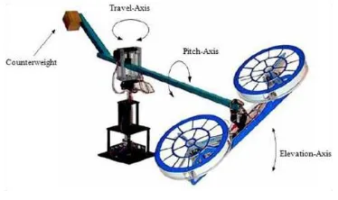
The 3DOF helicopter consists of a base upon which a long arm is mounted. The arm
carries the “helicopter body” on one end
and a counterweight on the other. The arm
can tilt about an “elevation” axis as well as
swivel about a vertical (travel) axis. Quadrature optical encoders mounted on these axes allow for measuring the elevation and travel of the arm. The pitch angle is measured via a third encoder. Two motors with propellers mounted on the
helicopter body can generate a force proportional to the voltage applied to the motors. The force generated by the propellers causes the helicopter body to lift off the ground. The purpose of the counterweight is to reduce the power requirements on the motors. Electrical signals to and from the arm and helicopter are channeled through the slipring to eliminate tangled wires, reduce friction and allow for unlimited and unhindered travel.
The purpose of the experiment is to design a PID controller to maneuver the helicopter body to track and regulate the elevation and travel of the 3DOF Helicopter.
The paper is organized as follows. Dynamic model of a helicopter is provided in Section II. Designing the control system is presented in Section III. The simulation results are provided in Section IV. In Section V, we conclude with conclusion.
DYNAMIC MODEL
The research presented in this paper is based on a mathematical model of a 3-DOF
laboratory helicopter system from Quanser Consulting, Inc. The 3-DOF helicopter consists of a base upon which an arm is mounted. The arm carries the helicopter body on one end and a counter weight on the other end. The arm can pitch about an elevation axis as well as swivel about a vertical axis. Encoders that are m
The research presented in this paper is based on a mathematical model of a 3-DOF laboratory helicopter system from Quanser Consulting, Inc. The 3-DOF helicopter consists of a base upon which an arm is mounted. The arm carries the helicopter body on one end and a counter weight on the other end. The arm can pitch about an elevation axis as well as swivel about a vertical (travel) axis. Encoders that are mounted on these axes allow measuring the elevation and travel of the arm. The helicopter body is mounted at the end of the arm and is free to swivel about a pitch axis. The pitch angle is measured via a third encoder. Due to hardware restrictions, the movement range of the elevation and pitch angles are constrained within [-1, +1] rad. Two DC motors with propellers mounted on the helicopter body can generate a force proportional to the voltages applied to the DC motors. The force generated by the propellers can cause the helicopter body to lift off the ground. The purpose of the counterweight is to reduce the power requirements on the motors. The 3DOF helicopter plant is shown in Figure 1.
The system dynamics can be described by the following state model [1,3]:
where
(2)
(3)
(4)
(5)
(6)
(7)
(8)
(9)
Figure 1. Laboratory Helicopter from Quanser Consulting, Inc
The symbols used in the above model are described in Table 1.
Table 1. Notation and units used in the laboratory helicopter model
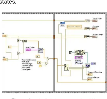
The model has been implemented in LabVIEW. Figure 2 shows Front Panel of LabVIEW program and Figure 3 shows the Block Diagram. This model simulates system dynamics and measurement. It reduces the A and B matrices to a set of integrators and gains. The elevation integrator is limited to positive values in order to simulate the helicopter landing on the ground. Augmenting the motor voltages by the constant simulates gravitational bias. Multiplying by a calibration constant that converts radians t o d eg rees s i m u l a t es en c od er
measurements. Because high-pass filters function as differentiators at frequencies below the passband, they are used to differentiate the three displacement states.
Figure 3. Block Diagram of 3 DOF Helicopter Simulation in LabVIEW
DESIGNING THE CONTROL SYSTEM
In this section a linear Proportional-Integral-Derivative (PID) controller is designed to regulate the elevation and travel angles of the 3-DOF Helicopter to desired positions. The PID control gains are computed using the Linear-Quadratic Regular algorithm.
Using the weighting matrices
and
and the state-space matrices (A,B) found previously, the control gain
is calculated by minimizing the cost function
with the Matlab LQR command. Examining the feedback gains obtained from LQR design, we note the following feature : the second row gains have the exact same magnitudes as the first row.
Further examination reveals that the sum of the rows results in :
which can be re-written as
which is the Proportional+Integral+ Derivative (PID) controller about the elevation axis.
Examining the difference between the gains, the feedback loop can be decomposed into two loops : one for pitch and one for travel.
The above equation can be re-written as.
which is a PD loop to command the pitch to track the desired pitch. The desired pitch is defined as.
which is another PID loop that controls the travel position. We now have the following control equations.
(10)
(11)
(12)
(13)
(14)
(15)
(16)
(17)
(18)
(19)
And we obtain
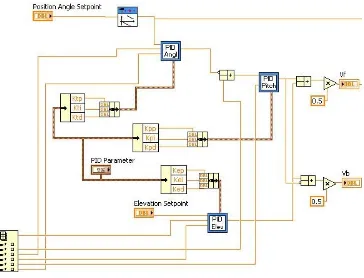
The implementation of the controller is shown in figure 4 – 7. It consists of three loops. The pitch command is limited to +/- 90 degrees.
SIMULATION RESULTS
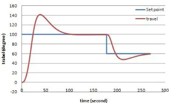
In this simulation, the reference signals for the elevation and travel angles are changes between 100o to 60o and between 20o to 10o to simulate the demands given by the pilot as shown in Figure 8 and Figure 9. Also, the sampling time and simulation time used are 0.1 and 270 seconds, respectively.
Figure 10 and Figure 11 shows the transient response and steady-state response of the elevation angle and travel angle to step signal. From Figure 10 and Figure 11, one sees that the percent overshoots of elevation and travel angles are approximate to 22.5 % and 40 % respectively. The settling time of elevation and travel angles are approximate to 10s and 20s with 5% criterion. And the steady state error of the elevation and travel angles are approximate to zero.
The corresponding voltage signals applied to the rotors are shown in Figure 12 and Figure 13.
(21)
(22)
(23)
(24)
Figure 4. LabVIEW Feedback Controlled Block Diagram
Figure 5. PID Angle Controller
Figure 8. Reference signal for the elevation angle
Figure 9. Reference signal for the travel angle
Figure 10. Control simulation results for the elevation angle
Figure 11. Control simulation results for the travel angle
Figure 12. Voltage applied on the front motor
It can be seen from the Figures 10 and Figure 11 that when the helicopter is operating in a wide range of its flight envelope, the tracking performance looks acceptable; however, large overshoot is not avoidable.. This is shown in Tables 3 which show the percent overshoot and settling time for the control algorithms
Table 3. Overshoot and Settling time for elevation and travel control
CONCLUSIONS
In this paper, we have presents a LQR control the elevation and travel of a laboratory helicopter system. The performance of the algorithm is illustrated and the results show a good performance in term of tracking error, overshoot and settling time.
REFERENCES
Apkarian J., 3d Helicopter Experiment
Manual, Canada : Quanser Consulting, 1998
Baris E Perk, Motion Primitives for Robotic Flight Control, 2008
C. C. Ko, Ben M. Chen, A Web-Based Laboratory on Control of a Two-Degrees-of-Freedom Helicopter, Int. J. Engng Ed. Vol 21, No 6, pp 1017-1030, 2005
Fabricio Galende Marques de Carvalho,
Adaptive Elevation Control of a Three Degrees-of-Freedon Model Helicopter Using Neural Networks by State and Output Feedback, ABCM Symposium Series in Mechatronics Vol 3, pp 106-113, 2008
Jacob Apkarian, Systematic Controller Design and Rapid Prototyping
Jonas Witt, Approximate Model Predictive Control for Nonlinier Multivarible Systems, Hamburg University of Technology Germany
Mariya A. Ishutkina, Design and Implementation of a Supervisory Safety Controller for a 3DOF Helicopter, Thesis at Massachusetts Institute of Technology, 2004
Quanser Innovate Educate, Aerospace Plant : 3-DOF Helicopter Reference Manual
Simon Westerberg, Motion Planning and Control of an Underactuated 3DOF Helicopter
Yao Yu, Yishing Zhong, Robust Attitude Control of a 3DOF Helicopter with Multi-Operation Points, Jrl Syst Sci & Complexity, pp 207 – 219, 2009