Resistive Products
Application Note
NTC Thermistors
APPLIC
ATION N
O
TE
APPLICATIONS
AUTOMOTIVE APPLICATIONS
NTC temperature sensors are widely used in motor vehicles. For example:
• Inlet air-temperature control
• Transmission oil temperature control • Engine temperature control
• Airco systems
• Airbag electronic systems
• Temperature detection of laser diode in CD players for cars
• Frost sensors • ABS
DOMESTIC APPLIANCES
NTC temperature sensors are in virtually all equipment in the home where temperature plays a role. This includes • Fridges and freezers
• Cookers and deep-fat fryers
• Washing machines and dish washers • Central-heating systems
• Air conditioning
INDUSTRIAL, TELECOMMUNICATIONS, CONSUMER
In switching, measuring and detection systems • Process control
• Heating and ventilation • Air conditioning • Fire alarms
• Temperature protection in battery management/charging systems
• LCD contrast control in flat-panel displays, mobile phones and camcorders
• Temperature compensation of quartz oscillator frequency in, for example, mobile phones
• Ink-jet printer head temperature detection • Video and audio equipment
SELECTION CHART
PRODUCT RANGE
OPERATING TEMP. RANGE
(°C)
TOL.
ON R (± %)
OR ON T (± °C)
B TOL. (± %)
RESP. TIME
(s)
MAX. Ø (mm)
LEAD
DOCUMENT NUMBER Ø
(mm) L (mm)
Accuracy line
NTCLE203E3 - 40 to + 125 (1 , 2, 3, 5) % 0.5 to 2.5 1.7 3.4 0.4 38 min. 29048 NTCLE100E3 - 40 to + 125 (2, 3, 5) % 0.5 to 3.0 1.2 3.8 0.6 17 min. 29049 NTCLE101E3...SB0 - 40 to + 125 0.5 °C two-point
sensors 1.2 3.3 0.6 17 min. 29046
NTCLE203E3...SB0 - 55 to + 150 0.5 °C two-point sensors 1.7 4.2 0.5 41 29118 SMD versions
NTCS0603E3 - 40 to + 150 (1, 2, 3, 5) % 1 - - - - 29056
NTCS0402E3 - 40 to + 150 (1, 2, 3, 5) % 3 - - - - 29003
NTCS0805E3 - 40 to + 150 (1, 2, 3, 5) % 1 - - - - 29044
Miniature accuracy line
NTCLE300E3 - 40 to + 125 0.5 °C 1.2 1.2 2.4 AWG30 38 29051
NTCLE201E3 - 40 to + 125 0.5 °C 1.2 1.3 2.4 0.3 38 29051
NTCLE305E4 - 40 to + 125 0.5 °C 0.5 to 1 0.7 1.6 AWG32 41 29076
High temperature
NTCSMELFE3 - 40 to + 150 5 % 1.3 0.9 1.7 - - 29119
NTCLG100E2 - 40 to + 300 5 % 1.3 0.9 1.85 0.56 max. 25.4 min. 29050
Special long-leaded (UL2468 PVC insulation):
NTCLS100E3 - 40 to + 85 3 % 0.75 to 3 15 8 AWG24 400 29060
NTCLP100E3 - 40 to + 85 3 % 0.75 to 3 10 6 AWG24 400 29060
NTCLE400E3 - 40 to + 85 3 % 0.75 to 3 7 6 AWG24 400 29060
Ring Tongue Sensors
NTCALUG02 series - 55 to + 125 (1, 2) % 0.5 5 8.5 AWG32 45 29094
NTCALUG03 series - 40 to + 125 (2, 3) % 0.5 to 1.5 5 5.5 AWG32 70 29114
O
N NOTE
Revision: 24-May-12 2 Document Number: 29053
RANGE SUMMARY
ACCURACY LINE
NTCLE203E3 and NTCLE100E3
The flagship of our ranges. The accuracy Line sensors offer real value for money. They have low tolerances (as low as ± 1 % on the R25-value and ± 0.5 % on the B-value) and an
operating temperature range from - 40 °C to + 125 °C. In addition, they are very stable over a long life.
SURFACE MOUNT TEMPERATURE SENSORS
NTCS0402, NTCS0603 and NTCS0805 series
Our surface mount NTC sensors for temperature sensing and compensation embody all the qualities of Vishay BCcomponents NTC technology. The sensors come in a full range of R25-values from 2 k to 680 k with standard
tolerances from 1 % to 5 %.
HIGH-TEMPERATURE SENSORS
NTCSMELFE3 and NTCLG100E2
This range of high-quality glass-encapsulated NTC temperature sensors are price-competitive for general use. Not only can theleaded sensor be used at up to 300 °C, but their glass encapsulation makes them ideal for use in corrosive atmospheres and harsh environments. This makes them an attractive alternative to other more expensive sensing methods. Two types of small glass envelopes are available: SOD 27 for sensors with leads, and SOD 80 (‘MELF’ execution) for leadless, surface mount sensors.
AUTOMOTIVE SENSORS
NTCLE203E3...SB0
These components are designed for all automotive applications (especially ECT sensors). Their coating is withstanding harsh potting conditions. These components are compliant to the AEC-Q200 norm.
MINIATURE CHIP ACCURACY LINE
NTCLE201E3 NTCLE300E3 NTCLE305E4
These sensors combine the features of the accuracy line with non-insulated or insulated leads for remote sensing applications.
SPECIAL LONG-LEADED SENSORS
NTCLS100E3 NTCLP100E3 NTCLE400E3
For special applications we can supply three types of long-leaded sensors: water-resistant sensors for use in humid conditions, pipe sensors for use in corrosive atmospheres and epoxy-coated sensors for general use.
SURFACE TEMPERATURE SENSORS
NTCALUG01 NTCALUG02 NTCALUG03
HOW NTC TEMPERATURE SENSORS WORK
NTC temperature sensors are made from a mixture of metal oxides which are subjected to a sintering process that gives them a negative electrical resistance versus temperature (R/T) relationship such as that shown in figure 1.
Fig. 1 - Typical resistance as a function of temperature for an NTC temperature sensor.
The relatively large negative slope means that even small temperature changes cause a significant change in electrical resistance which makes the NTC sensor ideal for accurate temperature measurement and control.
The main electrical characteristics of an NTC ceramic temperature sensor are expressed by three important parameters and their tolerances (see below).
RESISTANCE R25 AT 25 °C (289.15 K)
The resistance at 25 °C (substantially at room temperature) provides a convenient reference point for thermistors. Tolerances on R25 are due mainly to variations in ceramic
material manufacture and tolerances on chip dimensions. Through the use of highly homogeneous material compositions and proprietary ceramic sawing techniques allowing precise control of chip dimensions, products are available with tolerances on R25 lower than 1 %.
IMPORTANT NTC PARAMETERS
PARAMETER DESCRIPTION
R25 The resistance of the sensor in reference temperature of 25 °C at the
B-value A material constant, expressed in Kelvin
The temperature coefficient of resistance expressed in %/K or in %/°C
MSB236 - 1
R25
B = 3740 K
B = 4570 K
O
N NOTE
MATERIAL CONSTANT B
B is a material constant that controls the slope of the RT
characteristic (see figure 1) which can, at least to a first approximation, be represented by the formula:
(1)
Where T is the absolute temperature of the sensor.
In practice, B varies somewhat with temperature and is therefore defined between two temperatures 25 °C and 85 °C by the formula:
(2)
B25/85 (expressed in K) is normally used to characterize and
compare different ceramics. Tolerance on B (or B25/85) is
caused mainly by material composition tolerances and sintering conditions. The latest materials offer tolerances as low as ± 0.3 % on some specific B25/85 values.
In most cases, better fitting curves than pure exponential are required to measure the temperature accurately; see formula (1). That is why each NTC material curve is defined
by a 3rd order polynominal, as shown below:
(3)
or inversely expressing T as a function of RT:
(4)
The two approximations (3) and(4) represent the real material
curves with an error smaller than 0.1 % at any given temperature.
The values of the coefficients A, B, C, D, A1, B1, C1 and D1
are given in some datasheets as NTCLE100E3 and in the
R-T computation sheets, which can be downloaded from the website
www.vishay.com/thermistors/curve-computation-list
SENSOR TOLERANCES
The total tolerances of the NTC sensor over its operating temperature range is a combination of the tolerances on R25
and on B-value given by the formula:
(5)
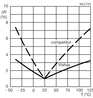
Figure 2 is a graphical representation of this formula which shows a minimum at 25 °C since this is the temperature at which the sensor is calibrated. Above and below this temperature, the tolerances increase due to the increasing tolerances on B-value, giving the graph a ‘butterfly’ shape.
Fig. 2 - Typical resistance change as a function of temperature for a 1 % Vishay NTC temperature sensor compared to a
1 % sensor with a higher B-tolerance
The exceptionally low B-value of the Vishay BCcomponents sensor compared with those of typical competitors (see figure 2) gives a flatter R/R ‘butterfly’ curve which means you can get more accurate temperature measurements using Vishay BCcomponents NTC temperature sensors.
TEMPERATURE COEFFICIENT OF RESISTANCE
The temperature coefficient of resistance expresses the sensitivity of a sensor to temperature changes. It is defined as:
(6)
Using formula to eliminate R this can be re-expressed as:
(7)
Which means that the relative tolerance on is equal to the relative tolerance on B-value.
THERMAL STABILITY
The stability of an NTC temperature sensor is expressed in terms of the maximum shift in its electrical properties, R25
and B-values after it has been subjected to an extended period at its limit operating conditions. Figure 3, for example, shows the long-term deviation of R25 and B-value
O
N NOTE
Revision: 24-May-12 4 Document Number: 29053
Fig. 3 - Aging characteristics (dry heat at 150 °C of a NTCLE100E3 series NTC temperature sensor with an R25 of 10 k
TEMPERATURE CYCLING
Another important criterion for assessing the performance of an NTC sensor throughout its operational life is its resistance to thermal cycling. To assess this, products are subjected to rapid temperature variations covering the extremes over which they are expected to operate until failure is induced.
These tests fully demonstrate the high reliability of our products: our soldered types (for example NTCLE300E3 types) withstanding more than 5000 cycles, and our glass encapsulated types (NTCLG100E2) more than 100 000 cycles without failure.
THERMAL TIME CONSTANT AND RESPONSE TIME
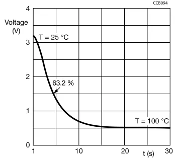
The speed of response of an NTC sensor is characterized by its time constant. This is the time for the sensor’s temperature to change by 63.2 % (i.e. 1 to 1/e) of the total change that occurs when the sensor is subjected to a very rapid change in temperature.
The conditions under which the time constant is measured are important. Two are normally considered:
• Ambient change: the component is initially in still air at 25 °C. Then quickly immersed in a fluid at 85 °C. The fluid is usually silicone oil but other fluids, e.g. water for washing machine applications, air for tumble dryers can also be specified.
• Power-on/power-off conditions: the component is heated by applying electrical power in still air to an equivalent temperature of 85 °C after which electrical power is removed and cool-down time is measured at 63.2 % of the temperature difference.
Figure 4 represents the typical voltage drop variation over a boiler sensor experiencing a transition from air at 25 °C to the temperature of boiling water. The graph shows a response time of about 4 s when the measured voltage corresponds to an equivalent temperature of 72.4 °C.
Fig. 4 - Typical output of a boiler sensor undergoing a sudden temperature transition from 25 °C to 100 °C
ADVANCED DEVELOPMENT AND HIGH-TECHNOLOGY MANUFACTURE
The high accuracy of our NTC temperature sensor series is principally a result of advanced development and high-technology manufacture.
ADVANCED DEVELOPMENT
Audits of our factory by major customers especially in the automotive industry regularly award us top marks. This is the result of strong commitment to development and heavy investment in personnel and equipment. Only by such commitment have we been able to develop new and better materials with B-value tolerances as low as 0.3 %.
HIGH-TECHNOLOGY MANUFACTURE
Our most significant improvement in NTC temperature sensor manufacture has come through the use of precision sawing. This gives much better control over repetitive
R25-value than the earlier pressing or tape casting
techniques and has allowed us to achieve R25 tolerances
lower than 1 %. After manufacture, we electrically test every one of our NTC temperature sensors at reference or other temperatures.
COMPONENT QUALITY, OUR GUARANTEE OF EXCELLENCE
As you expect from a world-class electronic components manufacturer, quality is an integral part of our company’s make-up. It is reflected in our ISO-TS 16949 approved organizations, all of which operate according to the principles of TQM (Total Quality Management). It is reflected too in the way we act, think and do business. Quality, in fact, is the essence of what we have to offer:
not just in our products but in our customer service and customer relations as well.
0.20 CCB434
- 0.20 - 0.15 - 0.10 - 0.05 0 0.10
0.05
104 103
102 Time (h)
Shift in B25/85
(%)
min. max.
average
1 10
4
3
1
0 2
CCB094
20 30
Voltage (V)
t (s) T = 25 °C
O
N NOTE
Our Quality Assurance system is based on the following principles:
• Total quality management involving careful design and thorough investigation of conformance and reliability before release of new products and processes.
• Careful control of purchased materials and manufacturing process steps. This is mainly achieved by strict implementation of Statistical Process Control (SPC) to detect and eliminate adverse manufacturing trends before they become significant.
• Electrical inspection of significant characteristics with a target of zero defects in our delivered sensors.
• Statistical inspection of outgoing batches and periodic reliability checks aimed at collecting trend information, which is steered towards Quality improvement.
• Quality assurance at Vishay BCcomponents goes further, however. Batch tests under extreme climatic conditions are designed to test our sensors to destruction. Results clearly indicate that Vishay BCcomponents NTC sensors provide reliable performance over a long lifetime. A fact that has been verified by ppm figures obtained from many years of close cooperation with major customers in all sectors of industry. Proving conclusively that Vishay BCcomponents NTC temperature sensors offer unsurpassed levels of quality and reliability in the field.
SELECTING AN NTC TEMPERATURE SENSOR
STEP 1
Decide on the sensor series you need from the “Selection Chart”
Your choice depends on the operating temperature range and other criteria such as:
• Accuracy • Product size
• Required mechanical execution i.e. naked chip, SMD, epoxy coated, moulded, surface sensor or glass sealed • Lead length and diameter.
STEP 2
Decide on the value of R25 you need. Refer to the
R/T characteristics of the sensor series you chose in Step 1. In these characteristic curves, each sensor in the series is distinguished by its R25-value. Choose an R25-value to give
a resistance at your average temperature of operation of between 1 k and 100 k or the value that best fits your electronic measuring circuit voltage and current range.
STEP 3
Determine the tolerance on R25. Generally, you will know the
accuracy of T at which the temperature should be measured in your application. The relative tolerance (R/R) on sensor resistance is then: R/R = x T in which ’’ is the temperature coefficient of resistance; see section “Temperature Coefficient of Resistance”. To calculate the relative tolerance on R25 (R25/R25), simply subtract from
R/R the R tolerance due to B-value.
STEP 4
Using the R/T tables of the respective datasheets, select the sensor from the series meeting your requirements on
calculated in step 3.
Use the RT computation files, which can be downloaded
from the website for most of the NTC thermistors (leaded or SMD) at www.vishay.com/thermistors/curve-computation-list
STEP 5
For other important requirements such as response time and length of component, refer to the “Selection Chart”. Although the standard range gives the narrowest tolerances at 25 °C , we can on request, adapt our manufacturing processes to provide products with the narrowest tolerance at any temperature of your choice. Please pass your request through your local Vishay sales organization.
EXAMPLES ON HOW TO SELECT
EXAMPLE 1
A leaded NTC sensor is required for sensing temperatures in refrigerator and freezer compartments with a temperature accuracy of 0.5 °C over the whole temperature range of - 25 °C to + 10 °C. Over this temperature range, the circuit design requires that the resistance should be maintained between 2 kand 30 k.
STEP 1
Choose the execution. Since temperature has to be measured with high accuracy, small diameter nickel leads are recommended. Their low heat conductivity effectively isolates the component from the outside world, enabling it to accurately monitor the temperature of the freezing compartments. From the “Selection Chart” it can be seen that NTCLE203E3 series components are the most suitable choice.
STEP 2
Refer to the NTCLE203E3 series datasheet specifications. The component meeting the requirement that the resistance should be maintained between 2 k to 30 k is a NTCLE203E3202xB0 type (x indicating the tolerance).
STEP 3
Calculate the required tolerance on R25. Knowing that
T = ± 0.5 K and taking values for at - 25 °C and 10 °C from the NTCLE203E3 specifications:
= 2.71 % at - 25 °C
= 2.13 % at 10 °C
To calculate the relative tolerance on R25 (R25/R25), simply
subtract from R/R, the R tolerance due to B-value at these two temperatures obtained from this datasheet.
O
N NOTE
Revision: 24-May-12 6 Document Number: 29053
= 2.71 % - 1.19 % = 1.52 % at 25 °C
= 2.13 % - 0.31 % = 1.82 % at + 10 °C
Take the minimum which gives an R25 tolerance of 1 %. The
selected component is therefore NTCLE203E3202FB0.
STEP 4
Not applicable.
STEP 5
Suppose now that the required R25/R25 had been less than
1 %. Though no standard product meets that requirement, it's nevertheless possible to specify custom products with a different reference point, e.g. 0 °C instead of 25 °C that meet narrower tolerance specifications.
EXAMPLE 2
Designing a fast-charging circuit for nickel hydride cells. During fast charging, the rate of temperature rise of the cells must be monitored. If this reaches 1 K/min with a tolerance of ± 10 %, the circuit must switch from fast charging to trickle charge. Ambient temperature must be between 10 °C to 45 °C to allow fast charging and the backup cut-off temperature (above which charging is completely switched off) is fixed at 60 °C. Temperatures are expected to be measured with an accuracy of ± 2 °C.
STEP 1
Surface mount products can be used for this application. Since SMDs for relatively low temperatures are needed, refer to the NTCS series rather than NTCSMELF series.
STEP 2
Choose the R25 of the component. From the R/T
specifications of the NTCS series, it can be seen that a type with an R25= 100 kis suitable i.e. NTCS0603E3104xXT.
STEP 3
It is possible to choose R25 tolerance from 1 % to 5 %.
Looking in the R-T computation curve for NTCS0603 100 k, we have an accuracy at 60 °C of 1.73 °C for a
R25 tolerance of ± 5 %, an accuracy of 1.19 °C for a
R25 tolerance of ± 3 %. We choose thus a R25 tolerance of
± 5 %.
STEP 4
The optimal sized sensor with good accuracy to choose is therefore the NTCS0603E3104JXT.
STEP 5
Verify now that the selected component fulfils the requirement with regard to rate of temperature rise (T/t), from section “Temperature Coefficient of Resistance”:
So to assure a maximum rate of temperature rise of 1 K/min we get (taking the and R -values at 60 °C from the specifications):
x 23 820 = - 881 /min
This is verified by measuring the rate of change of voltage (dV/dt) across the sensor at constant current I. The rate of change of resistance R/t can then be determined (= 1/IV/t).
At the same temperature, an NTC sensor with R and B-values at the extremes set by the sensor tolerances will have:
A resistance of 23 820 x (1 - 6.40/100) = 22 296 an of - 3.70 x (1 - 1/100) = - 3.66 % K
(tolerance on = tolerance on B25/85).
So the same R/t, i.e. - 881 /min in this extreme component will limit the maximum rate of temperature rise T/t to 881 x 100/3.66 x 1/22 296 = 1.082 K/min which still falls within the tolerance of ± 10 % allowed on the rate of temperature rise (1 K/min + 10 % = 1.1 K/min).
APPLICATION GROUPING
Applications of Vishay’s NTCs may be classified into two main groups depending on their physical properties: 1. Temperature sensors: Applications in which the sensitive
change of the resistance versus the temperature is used, shown in the formula:
This group is split into two subsections:
a) The temperature of the NTC thermistor is determined only by the temperature of the ambient medium. b) The temperature of the NTC thermistor is also
determined by the power dissipation in the NTC thermistor itself.
2. Time delay thermistors: Applications in which the time dependence is decisive, when the temperature is considered as a parameter and is written:
This group comprises all applications which make use of the thermal inertia of NTC thermistors.
The classifications mentioned are supported by practical examples in figure 5 to 17.
R25
R25
---R25 R25
---R t
--- RT
t
---=
R T
--- 3.70
100
---=
R = f T
O
N NOTE
EXAMPLES
Fig. 5 - Temperature measurement in industrial and medical thermometers
Fig. 6 - Car cooling water temperature measurement with bimetal
Fig. 7 - Car cooling water temperature measurement with differential mA-meter
Fig. 8 - Temperature measurement with a bridge incorporating an NTC thermistor and a relay or a static switching device
Fig. 9 - Liquid level control
Fig. 10 - Flow measurement of liquids and gases. The temperature difference between T1 and T0 is a measure for the
velocity of the fluid or gas.
Fig. 11 - Temperature sensing bridge with op-amp which acts as differential amplifier. The sensitivity can be very high.
Fig. 12 - Basic temperature sensing configuration. The op-amp acts as a Schmitt-trigger. The transfer characteristic is shown
in figure 13 CCB526
- °C V
bimetal mA-meter
V
-
CCB527
°C
differential mA-meter V
CCB528 -
°C
CCB529 - V
CCB530 -
V
°C
CCB531
T1 T0
NTC NTC
Flow direction
Heater
V
CCB532 - q
VO
- V
-+ + V
CCB533 - q
VO
+ V
+
O
N NOTE
Revision: 24-May-12 8 Document Number: 29053
Fig. 13 - Transfer characteristic of the circuit shown in figure 12
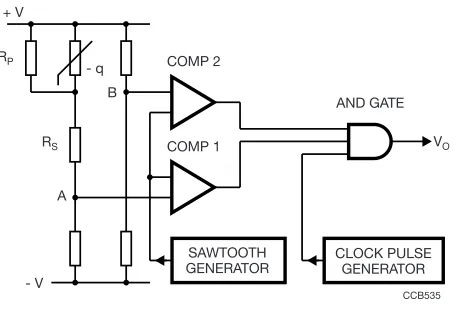
Fig. 14 - Temperature sensing bridge with 0 °C offset and ADC. Due to RP and RS the voltage at A varies linearly with the NTC
thermistor temperature. The voltage at B is equal to that at A when the NTC thermistor temperature is 0 °C. Both voltages are fed to the
comparator circuit. See also figure 15
Fig. 15 - Pulses occurring at various points in the circuit shown in
Fig. 14
Fig. 16 - Simple thermostat
Fig. 17 - Temperature compensation in transistor circuits. Push-pull compensation.
NTC TEMPERATURE SENSORS USED AS A THERMAL SWITCH
A common use of an NTC temperature sensor is in one of the bridge arms of a thermal switch circuit using an operational amplifier such as the μA 741. Figure 18 shows a typical thermal switch circuit for a refrigerator thermostat. The circuit consists of a 10 VDC zener diode stabilized power
supply, a wheatstone bridge (containing the NTC temperature sensor) and an integrated comparator circuit controlling a triac. The circuit is designed to switch a maximum load current of 2 A off at - 5 °C and on at + 5 °C.
Fig. 18 - Refrigerator thermostat using an NTC temperature sensor. t
VO
CCB534
CCB535 VO COMP 2
COMP 1 RP
RS B
A
SAWTOOTH GENERATOR
CLOCK PULSE GENERATOR AND GATE - q
+ V
- V
CCB536
AND GATE OUTPUT PULSES
VO COMP 2
VO COMP 1
SAWTOOTH TEMPERATURE 0 °C REF.
- q
- V + V
Relay
CCB537
- q
CCB538 + V
- V
~
MBD944
U
BT136-500D Triac green Rg 680 Ω
Rh
182 kΩ
μA 741
RP
10 kΩ
R2 R6
10 kΩ
R1 120
kΩ
R3
Cb
50 μF (16 V) Z1
10 V 400 mW D1
1N4148 Rd Cd 390 Ω 30 nF (400 V) R4
100 Ω
C11.5 μF (40 V)
R5 1 MΩ
F1 2A
Vm
230 V - q
O
N NOTE
HEAT DETECTION IN FIRE ALARMS
Fig. 19 - Circuit diagram of a typical heat detector using a matched pair of NTC thermistors.
FAST CHARGING CONTROL WITH NTC TEMPERATURE SENSING
Figure 20 shows the circuit diagram of an intelligent charged designed to charge,within 1 h, a NiCd or NiMH.
An NTC thermistor, together with fixed resistors RT1 and
RT2, is used in a voltage divider between VCC and the current
sense resistor input VSNS of the IC. At the beginning of a new
charge cycle, the IC checks if the voltage VTEMP = VTS - VSNS is within the limits designed by the IC
manufacturer (low temperature: 0.4 VCC and high
temperature: 0.1 VCC + 0.75 VTCO). VTCO is a cut of threshold
defined by external resistors (not represented in figure 1): If after starting the fast charge phase, VTEMP becomess lower
than VTCO, then the return to trickle mode is operated.
During the fast charge period, the IC samples the voltage VTEMP and the return to trickle mode can also be operated
when the variation in time of VTEMP is going over a threshold.
This is called the T/t termination: each 34 s, VTEMP has
fallen by 16 mV ± 4 mV compared to the value measured two samples earlier, then the fast charge is terminated.
For further information refer to Application Note “Fast Charging Control with NTC Temperature Sensing” (doc. 29089)
Fig. 20 - BQ2005
GLOSSARY OF TERMS
RESISTANCE
Also called nominal resistance. Formerly specified at only one temperature, or sometimes at two or maximum three. Now new technologies allow the specification of resistance values on all applicable temperature ranges for several types.
TOLERANCE ON RESISTANCE
The limits of the values that the resistance can take at the reference temperature.
B-VALUE
The B-value (expressed in K) may be calculated using the following formula:
where R1 and R2 are the nominal values of resistance at T1
and T2 respectively (T expressed in K).
TOLERANCE ON B-VALUE
The limits of the value that B can take due to process and material variations.
R-TOLERANCE DUE TO B-DEVIATION
Due to the tolerance on the B-value, the limits of the value that R can take at a certain temperature increase with the difference of that temperature to the reference temperature.
TOLERANCE ON R AT A TEMPERATURE DIFFERENT TO TREF
The sum of the tolerances on resistance and tolerance due to B-deviation.
-VALUE OR TEMPERATURE COEFFICIENT
Variation of resistance (in %/K) for small variations of temperature (1 °C or 1 K) around a defined temperature.
MAXIMUM POWER DISSIPATION AND ZERO POWER
Maximum power which could be applied without any risk of failure. The maximum dissipation of an NTC thermistor is derated in function of ambient temperature. At low temperatures a certain dissipation can generate high voltages across the sensor which are not allowed. Zero-power is practically limited to less than 1 % of maximum specified power dissipation only for low self-heating by measuring current.
DISSIPATION FACTOR
O
N NOTE
Revision: 24-May-12 10 Document Number: 29053
HOW TO MEASURE NTC THERMISTORS
The published RT-values are measured at the
temperature T.
The published B-value at 25 °C is the result of the measurement at 25 °C and that at 85 °C. Hence, these values should be used when checking.
The following general precautions have to be taken when measuring NTC thermistors:
• Never measure thermistors in air; this is quite inaccurate and can give deviations of more than 1 K. For measurements at room temperature or below, use low viscosity silicone oil, purified naphta or some other non-conductive and non-aggressive fluid. For higher temperatures use oil, preferably silicon oil.
• Use a thermostatic liquid bath with an accuracy and repeatability of better than 0.1 °C. Even if the fluid is well
stirred, there is still a temperature gradient in the fluid. Measure the temperature as close as possible to the NTC. • After placing the NTC in the thermostatic bath, wait until temperature equilibrium between the NTC and the fluid is obtained. For some types this may take more than 1 min. Make sure that the NTC sensor is at an adequate depth below the fluid level, as ambient temperature can be conducted though wires or clamps to the sensing element.