Universitas Kristen Maranatha i
REALISASI ROBOT CERDAS PEMADAM API BERODA KRCI 2009
(ROBOT LADY)
Disusun oleh :
Nama : Kristi Kosasih
NRP : 0522100
Jurusan Teknik Elektro, Fakultas Teknik, Universitas Kristen Maranatha,
Jl.Prof.Drg.Suria Sumantri, MPH No. 65, Bandung, Indonesia.
Email: [email protected]
ABSTRAK
Semakin berkembangnya suatu negara, maka semakin banyak aplikasi
teknologi yang diterapkan dalam kehidupan sehari-hari. Salah satu bentuk
teknologi yang banyak digunakan adalah bidang robotika. Perkembangan bidang
robotika jelas terlihat dari jenis, bentuk, serta kegunaan dari robot yang makin
banyak dan beragam. Peningkatan kualitas robot terutama pada sistem kontrolnya
akan semakin meningkatkan kemampuan robot. Robot dapat digunakan untuk
pekerjaan dengan tingkat bahaya yang tinggi, misalnya saja pekerjaan sebagai
petugas pemadam api. Sejalan dengan perkembangan bidang robotika, di
Indonesia semakin semaraknya perlombaan maupun kontes robot yang
diselengarakan, seperti Kontes Robot Cerdas Indonesia (KRCI).
Pada tugas akhir ini, robot cerdas pemadam api beroda diberi nama Robot
LADY. Robot LADY ini juga direalisasikan untuk mengikuti KRCI 2009. Robot
LADY menggunakan roda sebagai alat geraknya dan motor servo sebagai aktuator
dengan misi mencari dan memadamkan api pada arena lapangan. Robot LADY
juga dilengkapi beberapa jenis sensor, seperti sensor jarak ultrasonik, sensor
kompas, sensor flame detector, sensor thermal array, sensor warna, dan
microswitch. Robot LADY dikontrol menggunakan mikrokontroler AVR ATMega 16. Arena lapangan dibuat seperti miniatur ruangan-ruangan (rumah,
Universitas Kristen Maranatha ii
uneven floor. Jadi seakan-akan robot LADY ini mencari dan memadamkan api pada ruangan-ruangan (rumah, kantor, sekolah) berlantai satu yang sesungguhnya.
Berdasarkan percobaan yang dilakukan dapat dikatakan bahwa Robot
LADY dapat mencari dan memadamkan api lilin serta bernavigasi dan
bermanuver dalam mencari dan menjelajahi keempat ruangan mulai dari Home
sampai berhenti di Home kembali dengan mode hanging objects, variable door
location, uneven floor, furniture, non-arbitrary start, sound activation, return trip mode, room factor 4 (RF4), dan memadamkan api dengan menggunakan tiupan angin dari kipas. Percobaan berhasil pada empat konfigurasi lapangan yang
digunakan dengan persentase keberhasilan sebesar 80.13 %.
Kata kunci: robot cerdas pemadam api beroda, mikrokontroler AVR ATMega
16, motor servo, sensor jarak ultrasonik, sensor kompas, sensor flame detector,
iii
Universitas Kristen Maranatha REALIZATION OF THE KRCI 2009 INTELLIGENT FIRE FIGHTING
WHEELED ROBOT (ROBOT LADY)
Composed by:
Name : Kristi Kosasih
NRP : 0522100
Electrical Engineering, Maranatha Christian University,
Jl. Prof.Drg.Suria Sumantri, MPH No. 65, Bandung, Indonesia.
Email: [email protected]
ABSTRACT
Nowadays technology contribution in our life is more than as we expected,
especially robotic. Robotic development can be known through type, shape, and
usefulness. Robot can be used for high risk task such as fire fighting. Fire fighting
robot should be able to search certain area, find the flame, and extinguish the fire.
To complete these tasks, robot should be equipped with a proper controller.
Because of this issue, Indonesia government organizes ‘Kontes Robot Cerdas
Indonesia’ (KRCI).
In this final project, the intelligent fire fighting wheeled robot named robot
LADY was prepared for KRCI 2009, wheeled senior division. Robot LADY is
equipped with ultrasonic sensor, compass sensor, flame detector sensor, thermal
array sensor, white detector sensor, micro switch which are controlled by
Microcontroller ATMEGA 16. The area is designed like house, school, or office
but in miniature. The miniature is equipped with furniture, sound damper, and
uneven floor.
The criteria in KRCI 2009, wheeled senior division are hanging objects
mode, variable door location mode, uneven floor mode, furniture mode,
non-arbitrary start mode, sound activation mode, return trip mode, room factor 4 (RF4)
mode, and extinguish fire source with fan. The task is to find the flame, extinguish
Universitas Kristen Maranatha iv
robot LADY can completes the task with 80.13% of succeed for 4 area
configurations.
Keywords : intelligent fire-fighting wheeled robot, microcontroller AVR
ATMega16, ultrasonic sensor, compass sensor, flame detector sensor, thermal
Universitas Kristen Maranatha v
KATA PENGANTAR
Segala puji syukur kami panjatkan ke hadirat Tuhan Yang Maha Esa atas
segala rahmat dan karunia-Nya sehingga penulis mampu menyelesaikan tugas
akhir ini dengan baik dan tepat pada waktunya di Laboratorium Sistem Kontrol.
Laporan tugas akhir yang berjudul “REALISASI ROBOT CERDAS
PEMADAM API BERODA KRCI 2009 (ROBOT LADY)” ini disusun untuk
memenuhi persyaratan program studi sarjana strata satu (S-1) Jurusan Teknik
Elektro, Fakultas Teknik Universitas Kristen Maranatha Bandung.
Selama pelaksanaan tugas akhir penulis telah mendapat banyak
bimbingan, dorongan, dan bantuan yang berarti dari berbagai pihak. Oleh karena
itu, penulis tidak lupa mengucapkan terima kasih kepada pihak-pihak yang telah
membantu dan mendukung dalam pengerjaan tugas akhir :
1. Ibu Dr. Erwani Merry Sartika, ST.MT. dan Bapak Meilan Jimmy Hasugian,
ST.MT., selaku dosen pembimbing tugas akhir telah bersedia meluangkan
waktu untuk memberikan penjelasan dan masukan yang berharga.
2. Bapak Muliady, ST.MT., yang telah menawarkan topik.
3. Bapak Muliady, ST.MT., Bapak Heri Andrianto, ST.MT., dan Bapak Ir Aan
Darmawan, MT., selaku penguji yang telah memberikan ide, kritik, dan
saran pada saat seminar dan sidang tugas akhir.
4. Bapak Dr.Ir Daniel Setiadikurnia, MT., selaku Kepala Jurusan Teknik
Elektro Universitas Kristen Maranatha.
5. Ibu Ir. Anita Supartono, M.Sc., selaku Koordinator Tugas Akhir Jurusan
Teknik Elektro Universitas Kristen Maranatha.
6. Tim Robot KRCI Maranatha, yang telah memberikan pengarahan, saran, dan
masukan.
7. Seluruh karyawan dan civitas akademika Universitas Kristen Maranatha yang
telah membantu dalam menyelesaikan laporan tugas akhir ini.
8. Keluarga tercinta yang telah memberikan perhatian, semangat, serta bantuan
doa dalam pelaksanaan dan penulisan laporan tugas akhir sehingga dapat
Universitas Kristen Maranatha vi
9. Saudara Herry Lukas yang terus memberikan perhatian dan dorongan dalam
menyelesaikan laporan tugas akhir ini.
10. Saudari Earline Ignacia Sutanto dan Marasella Tanusaputra sebagai Tim
Robot LADY yang telah memberi bantuan dan perhatian dalam
menyelesaikan laporan tugas akhir ini.
11. Semua rekan yang tidak dapat disebutkan satu persatu yang telah membantu
baik secara langsung maupun tidak langsung
Semoga Tuhan Yang Maha Esa membalas segala budi baik dan jasa Bapak, Ibu,
dan Saudara sekalian.
Penulis menyadari sepenuhnya bahwa masih banyak kekurangan dan
kesalahan dalam penulisan laporan tugas akhir ini, walaupun penulis telah
berusaha sebaik mungkin dengan segala kemampuan yang ada. Oleh karena itu,
dengan segala kerendahan hati, penulis mengharapkan saran dan kritik yang
membangun yang dapat menyempurnakan laporan tugas akhir ini. Semoga
laporan tugas akhir ini dapat bermanfaat bagi semua pihak yang membutuhkan.
Bandung, 21 Agustus 2009
Universitas Kristen Maranatha vii
DAFTAR ISI
Halaman
ABSTRAK ... i
ABSTRACT ... iii
KATA PENGANTAR... v
DAFTAR ISI... vii
DAFTAR TABEL ... xiii
DAFTAR GAMBAR... xv
BAB I PENDAHULUAN I.1 Latar Belakang ... 1
I.2 Identifikasi Masalah ... 2
I.3 Perumusan Masalah ... 2
I.4 Tujuan ... 2
I.5 Pembatasan Masalah ... 3
I.6 Spesifikasi Alat ... 4
Universitas Kristen Maranatha viii
BAB II LANDASAN TEORI
II.1 Pengantar Robotika ... 6
II.1.1 Sejarah Robot ... 6
II.1.2 Definisi Robot... 8
II.1.3 Keuntungan Penggunaan Robot ... 9
II.I.4 Klasifikasi Robot Berdasarkan Tingkat Kemampuan Melakukan Tugas ...10
II.1.5 Klasifikasi Robot Berdasarkan Mobilitas ... 10
II.1.6 Klasifikasi Robot Berdasarkan Metode Kontrol... 11
II.1.7 Sistem Kontrol Robotik ... 12
II.2 Kontes Robot Cerdas Indonesia (KRCI) 2009 ... 14
II.2.1 Latar Belakang KRCI 2009 ... 14
II.2.2 Maksud dan Tujuan Penyelengaraan KRCI 2009... 15
II.2.3 Divisi KRCI 2009 ... 16
II.2.4 Peraturan Divisi Senior Beroda ... 17
II.2.4.1 Robot dan Kelengkapannya ... 18
II.2.4.2 Arena Lapangan dan Kelengkapannya... 19
II.3 Motor DC Servo ... 23
Universitas Kristen Maranatha ix
II.4.1 Sensor Ultrasonik... 27
II.4.2 Sensor Kompas ... 31
II.4.3 Sensor Thermal Array... 36
II.4.4 Sensor UVTRON... 40
II.4.5 Microswitch... 42
II.4.6 Sensor Warna... 43
II.5 Rangkaian Sound Activation... 44
II.5.1 Pembangkit DTMF ... 45
II.5.2 Penerima DTMF ... 46
II.6 Mikrokontroler... 49
II.6.1 Pengenalan ATMEL AVR RISC... 49
II.6.2 Mikrokontroler ATmega16... 50
II.6.2.1 Fitur ATmega16 ... 50
II.6.2.2 Konfigurasi Pin ATmega16 ... 51
II.6.2.3 Diagram Blok ATmega16 ... 54
II.6.2.4 General Purpose Register ATmega16 ... 55
II.6.2.5 Peta Memori ATmega16 ... 55
Universitas Kristen Maranatha x
BAB III PERANCANGAN DAN REALISASI
III.1 Perancangan dan Realisasi Perangkat Keras Robot LADY ... 60
III.1.1 Mekanik Robot LADY ... 60
III.1.2 Elektronik Robot LADY... 63
III.1.2.1 Sensor ... 63
III.1.2.1.1 Sensor SRF04... 63
III.1.2.1.2 Sensor CMPS03... 64
III.1.2.1.3 Sensor TPA81... 64
III.1.2.1.4 Sensor UVTRON... 65
III.1.2.1.5 Microswitch... 65
III.1.2.1.6 Sensor Warna... 66
III.1.2.2 Sound Activation... 67
III.1.2.3 Motor Servo ... 68
III.1.2.4 Pemutar Kipas... 71
III.1.2.5 Skematik pengontrol berbasis mikrokontroler ATmega16... 72
III.2 Perancangan dan Realisasi Perangkat Lunak Robot LADY... 75
III.2.1 Perancangan Sistem Kontrol Robot LADY... 75
III.2.1.1 Diagram Blok Sistem Start Awal Robot LADY... 77
Universitas Kristen Maranatha xi
III.2.1.3 Diagram Blok Sistem Manuver Robot LADY ... 78
III.2.1.4 Diagram Blok Sistem Pemadaman Api Robot LADY ... 80
III.2.2 Algoritma pemrograman Robot LADY... 81
III.2.2.1 Diagram Alir Penggunaan Sensor... 81
III.2.2.2 Diagram Alir Pemrograman Robot LADY... 85
BAB IVANALISA DAN DATA PENGAMATAN IV.1 Pengujian Sensor Jarak Ultrasonik (SRF04) ... 92
IV.1.1 Pengukuran Jarak dengan Objek Multiplex... 93
IV.1.2 Pengukuran Jarak dengan Objek Cermin... 97
IV.1.3 Pengukuran Jarak dengan Objek Damper... 98
IV.2 Pengujian Sensor Kompas (CMPS03)... 102
IV.3 Pengujian Sensor Thermal Array (TPA81)... 105
IV.4 Pengujian Sensor UVTRON ... 107
IV.5 Pengujian Microswitch... 109
IV.6 Pengujian Sensor Warna... 111
IV.7 Pengujian Sound Activation... 112
Universitas Kristen Maranatha xii
BAB V SIMPULAN DAN SARAN
V.1 Simpulan ... 129
V.2 Saran………...130
DAFTAR PUSTAKA...131
LAMPIRAN – A Foto Robot LADY
LAMPIRAN – B Program pada Mikrokontroler ATMega16
LAMPIRAN – C Diagram Alir Program
LAMPIRAN – D Paduan KRCI 2009 Divisi Senior Beroda
LAMPIRAN – E Datasheet
LAMPIRAN – F Data Pengamatan Sensor SRF04
Universitas Kristen Maranatha xiii
DAFTAR TABEL
Halaman
Tabel 2.1 Register-register yang disediakan Sensor CMPS03... 33
Tabel 2.2 Register-register pada TPA81 ... 39
Tabel 2.3 Konfigurasi Tone DTMF ... 45
Tabel 2.4 Fungsional Decode (Mitel, 1993 : 8-27) ... 48
Tabel 2.5 Fungsi Khusus Port B ... 52
Tabel 2.6 Fungsi Khusus Port C ... 52
Tabel 2.7 Fungsi Khusus Port D ... 53
Tabel 3.1 Tabel Nilai OCR1x yang digunakan ... 71
Tabel 3.2 Alokasi Pin ATMega16 ... 73
Tabel 4.1 Tabel Pengukuran Jarak Multiplex dengan Sudut 90° Terhadap Sensor Jarak Ultrasonik (SRF04)... 94
Tabel 4.2 Tabel Pengukuran Jarak Multiplex dengan Sudut Bervariasi Terhadap Sensor Jarak Ultrasonik (SRF04)... 95
Tabel 4.3 Tabel Pengukuran Jarak Cermin dengan Sudut 90° Terhadap Sensor SRF04... 97
Tabel 4.4 Tabel Pengukuran Jarak Damper dengan Sudut 90° Terhadap Sensor Jarak Ultrasonik (SRF04)... 99
Tabel 4.5 Tabel Pengukuran Jarak Damper dengan Sudut Bervariasi Terhadap Sensor Jarak Ultrasonik (SRF04)... 100
Universitas Kristen Maranatha xiv
Tabel 4.7 Tabel Pengukuran Suhu Api Lilin dengan Sensor TPA81 dan
IRTex50 ... 106
Tabel 4.8 Tabel Pendeteksian Api Lilin dengan Sensor UVtron ... 108
Tabel 4.9 Tabel Pendeteksian Objek Putih Menggunakan Rangkaian Sensor
Warna ... 112
Tabel 4.10 Tabel Hasil Percobaan Pola Gerak Mencari dan Memadamkan Api
Lilin pada Pola 1 dengan Arah Awal Konfigurasi 4 ... 118
Tabel 4.11 Tabel Hasil Percobaan Pola Gerak Mencari dan Memadamkan Api
Lilin pada Pola 2 dengan Arah Awal Konfigurasi 5 ... 121
Tabel 4.12 Tabel Hasil Percobaan Pola Gerak Mencari dan Memadamkan Api
Lilin pada Pola 3 dengan Arah Awal Konfigurasi 6 ... 124
Tabel 4.13 Tabel Hasil Percobaan Pola Gerak Mencari dan Memadamkan Api
Universitas Kristen Maranatha xv
DAFTAR GAMBAR
Halaman
Gambar 1.1 Arena Lapangan ... 3
Gambar 2.1 Robot ASIMO dari Honda ... 7
Gambar 2.2 Robot AIBO dari Sony... 7
Gambar 2.3 Robot ApriPoko dari Toshiba ... 7
Gambar 2.4 Diagram Blok Sistem Kontrol... 12
Gambar 2.5 Kontrol Robot Loop Terbuka... 12
Gambar 2.6 Kontrol Robot Loop Tertutup ... 13
Gambar 2.7 Empat Konfigurasi Lokasi Pintu... 17
Gambar 2.8 Posisi Home pada mode non-Arbitary Start... 18
Gambar 2.9 Bentuk Motor Servo... 23
Gambar 2.10 Sistem Mekanik Motor Servo ... 23
Gambar 2.11 Diagram Blok Motor DC Servo dengan Kontrol Kecepatan ... 24
Gambar 2.12 Rangkaian Motor DC Servo dengan Kontrol Kecepatan... 25
Gambar 2.13 Nilai pulsa untuk menggerakkan motor servo ... 26
Gambar 2.14 Contoh Posisi dan Waktu pemberian Pulsa ... 27
Gambar 2.15 Bentuk Sensor SRF04 ... 28
Gambar 2.16 Dimensi Sensor SRF04 ... 28
Gambar 2.17 Alokasi PIN SRF04... 29
Gambar 2.18 Gambar Ilustrasi Cara Kerja Sensor SRF04... 29
Universitas Kristen Maranatha xvi
Gambar 2.20 Gambar Posisi Objek terhadap Sensor SRF04... 30
Gambar 2.21 Alokasi Pin CMPS03 ... 31
Gambar 2.22 Sketsa Sinyal PWM ... 32
Gambar 2.23 Bit Sequence I2C pada Sensor CMPS03... 32
Gambar 2.24 Rangkaian Tactile Switch untuk Proses Kalibrasi... 35
Gambar 2.25 Orientasi Sensor CMPS03 yang Menghasilkan Pembacaan Sudut 0° ... 35
Gambar 2.26 Sensor TPA81 Thermopille Array dan Dimensinya ... 36
Gambar 2.27 Alokasi Pin TPA81 ... 36
Gambar 2.28 Respon Spektral Sensor TPA81 antara 2 µm-22 µm ... 37
Gambar 2.29 Sudut Pandang Sensor TPA81 ... 37
Gambar 2.30 Bit Sequence I2C pada Sensor TPA81 ... 38
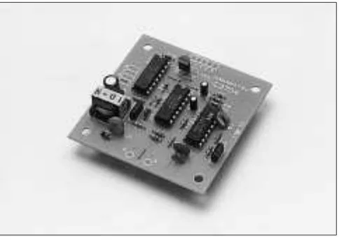
Gambar 2.31 UVTRON R2868 Flame Detector dan Hamamatsu C3704 Drive Circuit. ... 40
Gambar 2.32 UVTRON R2868 ... 40
Gambar 2.33 Grafik Respon UVTRON... 41
Gambar 2.34 Diagram Blok C3704 ... 41
Gambar 2.35 Microswitch 3 kaki... 42
Gambar 2.36 Keadaan 3 Kaki Microswitch... 43
Gambar 2.37 Rangkaian Sensor Warna Konfigurasi I... 44
Gambar 2.38 Rangkaian Sensor Warna Konfigurasi II ... 44
Universitas Kristen Maranatha xvii
Gambar 2.40 Pembangkit DTMF ... 46
Gambar 2.41 Penerima DTMF ... 47
Gambar 2.42 Diagram Blok IC Penerima DTMF MT8870... 47
Gambar 2.43 Konfigurasi Pin ATmega16 ... 51
Gambar 2.44 Diagram Blok ATmega16 ... 54
Gambar 2.45 General Purpose Register ATmega16 ... 55
Gambar 2.46 Peta Memori Program ATmega16 ... 56
Gambar 2.47 Peta Memori Data ATmega16 ... 56
Gambar 2.48 Phase & Frequency Correct PWM... 57
Gambar 3.1 Diagram Blok Robot LADY ... 59
Gambar 3.2 SRV-1 Mobile surveillance robot kit ... 60
Gambar 3.3 Struktur dan dimensi badan Robot LADY... 61
Gambar 3.4 Penempatan Sensor dan Rangkaian Sound Activation pada Robot LADY... 62
Gambar 3.5 Alokasi Pin Sensor SRF04 ... 63
Gambar 3.6 Alokasi Pin Sensor CMPS03 ... 64
Gambar 3.7 Alokasi Pin Sensor TPA81 ... 64
Gambar 3.8 Alokasi Pin Sensor UVTRON & Modul C3704 ... 65
Gambar 3.9 Konfigurasi Normally Open (NO) Microswitch... 65
Gambar 3.10 Konfigurasi Normally Closed (NC) Microswitch... 66
Universitas Kristen Maranatha xviii
Gambar 3.12 Rangkaian Pembangkit DTMF ... 67
Gambar 3.13 Rangkaian Penerima DTMF ... 68
Gambar 3.14 Alokasi Pin pada GWS.03 Continuous Rotation Servo ... 69
Gambar 3.15 Rangkaian Pemutar Kipas ... 71
Gambar 3.16 Skematik Pengontrol Berbasis Mikrokontroler ATMega16 ... 74
Gambar 3.17 Diagram Blok Sistem Kontrol Robot LADY... 75
Gambar 3.18 Kemungkinan Arena Lapangan... 76
Gambar 3.19 Diagram Blok Sistem Start Awal Robot LADY ... 77
Gambar 3.20 Diagram Blok Sistem Navigasi Robot LADY ... 77
Gambar 3.21 Diagram Blok Sistem Manuver Robot LADY... 78
Gambar 3.22 Diagram Blok Sistem Pemadaman Api Robot LADY... 80
Gambar 3.23 Diagram Alir Penggunaan Sensor SRF04... 82
Gambar 3.24 Diagram Alir Penggunaan Sensor CMPS03 ... 83
Gambar 3.25 Diagram Alir Penggunaan Sensor TPA81 ... 84
Gambar 3.26 Arah – arah sudut pada Arena Lapangan ... 85
Gambar 3.27 Diagram Alir Pemrograman Robot LADY Secara Umum ... 89
Gambar 3.28 Pergerakan Robot LADY pada Arena Lapangan Konfigurasi Pintu I...90
Gambar 3.29 Pergerakan Robot LADY pada Arena Lapangan Konfigurasi Pintu II...90
Universitas Kristen Maranatha xix
Gambar 3.31 Pergerakan Robot LADY pada Arena Lapangan Konfigurasi Pintu
IV...91
Gambar 4.1 Ilustrasi Cara Pengukuran Jarak Menggunakan Sensor Jarak
Ultrasonik (SRF04) ... 92
Gambar 4.2 Grafik Jarak Multiplex dengan Sudut 90° Terhadap Sensor Jarak
Ultrasonik (SRF04) ... 95
Gambar 4.3 Grafik Jarak Multiplex dengan Sudut Bervariasi Terhadap Sensor
Jarak Ultrasonik (SRF04)... 96
Gambar 4.4 Grafik Jarak Cermin dengan Sudut 90° Terhadap Sensor Jarak
Ultrasonik (SRF04) ... 98
Gambar 4.5 Grafik Jarak Damper dengan Sudut 90° Terhadap Sensor Jarak
Ultrasonik (SRF04) ... 100
Gambar 4.6 Grafik Jarak Damper dengan Sudut Bervariasi Terhadap Sensor
Jarak Ultrasonik (SRF04)... 101
Gambar 4.7 Ilustrasi Cara Pengukuran Sudut Menggunakan Sensor CMPS03
... 102
Gambar 4.8 Grafik Pengukuran Sudut dengan Sensor CMPS03 dan Kompas104
Gambar 4.9 Ilustrasi Cara Pengukuran Suhu Api Lilin Menggunakan Sensor
TPA81 ... 105
Gambar 4.10 Ilustrasi Cara Pendeteksian Api Lilin Menggunakan Sensor
UVTron ... 107
Gambar 4.11 Pendeteksian Objek Halangan dengan Konfigurasi Normally Open
Universitas Kristen Maranatha xx
Gambar 4.12 Pendeteksian Objek Halangan dengan Konfigurasi Normally
Closed (NC) dari Microswitch... 110
Gambar 4.13 Ilustrasi Pendeteksian Objek Berwarna Putih dengan Menggunakan Rangkaian Sensor Warna ... 111
Gambar 4.14 Ilustrasi Pengaktifan Robot LADY dengan Menggunakan Sound Activation... 112
Gambar 4.15 Konfigurasi Sudut Awal pada Home... 113
Gambar 4.16 Pola Gerak Navigasi dengan Sudut Awal Konfigurasi 1 ... 114
Gambar 4.17 Pola Gerak Navigasi dengan Sudut Awal Konfigurasi 2 ... 114
Gambar 4.18 Pola Gerak Navigasi dengan Sudut Awal Konfigurasi 3 ... 115
Gambar 4.19 Pola Gerak Navigasi dengan Sudut Awal Konfigurasi 4 ... 115
Gambar 4.20 Pola Gerak Navigasi dengan Sudut Awal Konfigurasi 5 ... 116
Gambar 4.21 Pola Gerak Navigasi dengan Sudut Awal Konfigurasi 6 ... 116
Gambar 4.22 Pola Gerak Mencari dan Memadamkan Api Lilin pada Pola 1 dengan Arah Awal Konfigurasi 4 Berdasarkan Algoritma ... 117
Gambar 4.23 Pola Gerak Mencari dan Memadamkan Api Lilin pada Pola 1 dengan Arah Awal Konfigurasi 4 ... 119
Gambar 4.24 Pola Gerak Mencari dan Memadamkan Api Lilin pada Pola 2 dengan Arah Awal Konfigurasi 5 Berdasarkan Algoritma ... 120
Universitas Kristen Maranatha xxi
Gambar 4.26 Pola Gerak Mencari dan Memadamkan Api Lilin pada Pola 3
dengan Arah Awal Konfigurasi 6 Berdasarkan Algoritma ... 123
Gambar 4.27 Pola Gerak Mencari dan Memadamkan Api Lilin pada Pola 3
dengan Arah Awal Konfigurasi 6 ... 125
Gambar 4.28 Pola Gerak Mencari dan Memadamkan Api Lilin pada Pola 4
dengan Arah Awal Konfigurasi 1 Berdasarkan Algoritma ... 126
Gambar 4.29 Pola Gerak Mencari dan Memadamkan Api Lilin pada Pola 4
LAMPIRAN A
A-1 Tampak Depan
A-2
Tampak Samping Kiri
A-3 Tampak Atas
A-4
Foto Pembangkit DTMF
LAMPIRAN B
PROGRAM PADA MIKROKONTROLER
B-1
PROGRAM UTAMA
/***************************************************** This program was produced by the
CodeWizardAVR V1.25.3 Standard Automatic Program Generator
© Copyright 1998-2007 Pavel Haiduc, HP InfoTech s.r.l. http://www.hpinfotech.com
.equ __i2c_port=0x12 ;PORTD .equ __sda_bit=6
.equ __scl_bit=7 #endasm
#include <i2c.h>
// Alphanumeric LCD Module functions #asm
B-2
// Declare your local variables here // Input/Output Ports initialization // Port A initialization
// Func7=In Func6=In Func5=In Func4=Out Func3=In Func2=Out Func1=In Func0=Out // State7=T State6=T State5=P State4=0 State3=P State2=0 State1=P State0=0
PORTA=0x2A; DDRA=0x15; // Port B initialization
// Func7=In Func6=In Func5=In Func4=In Func3=In Func2=In Func1=In Func0=In // State7=T State6=T State5=T State4=T State3=T State2=T State1=T State0=T PORTB=0x00;
DDRB=0x00; // Port C initialization
// Func7=In Func6=In Func5=In Func4=In Func3=In Func2=In Func1=In Func0=In // State7=T State6=T State5=T State4=T State3=T State2=T State1=T State0=T PORTC=0x00;
DDRC=0x00; // Port D initialization
// Func7=In Func6=In Func5=Out Func4=Out Func3=In Func2=In Func1=In Func0=In // State7=T State6=T State5=0 State4=0 State3=T State2=T State1=T State0=T PORTD=0x00;
DDRD=0x36;
// Timer/Counter 0 initialization // Clock source: System Clock // Clock value: Timer 0 Stopped // Mode: Normal top=FFh // Clock source: System Clock // Clock value: 1382.400 kHz
// Mode: Ph. & fr. cor. PWM top=ICR1 // OC1A output: Non-Inv.
// OC1B output: Non-Inv. // Noise Canceler: Off
B-3 // Input Capture Interrupt: Off
// Compare A Match Interrupt: Off // Compare B Match Interrupt: Off TCCR1A=0xA0; // Clock source: System Clock // Clock value: Timer 2 Stopped // Mode: Normal top=FFh
// Analog Comparator Input Capture by Timer/Counter 1: Off ACSR=0x80;
B-8
lorong_4a://kalo ruang 4nya yang satu lagi loop_3();
if(kiri<2)
B-11
SUBPROGRAM PENGGUNAAN SENSOR CMPS03
char bil1,bil2; int temp,sudut; void kompas (void) {
i2c_start(); i2c_write(0xc0); i2c_write(1); i2c_start(); i2c_write(0xc1); temp=i2c_read(1); bil2=i2c_read(1); bil1=i2c_read(0); i2c_stop();
sprintf(text,"%5d",temp); lcd_clear();
lcd_puts(text);
sudut=(bil2*256+bil1)/10; sprintf(text,"%5d",sudut); lcd_gotoxy(0,1);lcd_puts(text); delay_ms(50);
B-13 goto cekc;
} else goto backc; cekc: if(PINA.5==1) goto backc; else
jarakc=340*c/200; }
void lcd (void) {lcd_clear();
sprintf(text," %3d %3d %3d",jarakc,jarakb,jaraka); lcd_puts(text);
delay_ms(200); }
B-14
SUBPROGRAM MENJALANKAN RODA ROBOT
B-16
SUBPROGRAM MENGHINDARI HALANGAN FURNITURE
B-17
SUBPROGRAM UNTUK MELAKUKAN MANUVER
unsigned long int kanan,kiri; void loop_1 (void)
{
atas_lagi: furniture(); srf_kanan(); srf_depan(); srf_kiri(); lcd();
B-18
B-19
SUBPROGRAM UNTUK MENCARI POSISI API LILIN
unsigned long int ki,ka;
dapet: if(PINB.3==1) //sudah masuk lingkaran putih
B-20
dapet: if(PINB.3==1) //sudah masuk lingkaran putih
B-21
dapet: if(PINB.3==1) //sudah masuk lingkaran putih
LAMPIRAN C
C-1
C-14
DIAGRAM ALIR PROGRAM SENSOR TPA81
Keterangan :
data[0]= variabel yang berisi data register 1. data[1]= variabel yang berisi data register 2. data[2]= variabel yang berisi data register 3. data[3]= variabel yang berisi data register 4. data[4]= variabel yang berisi data register 5. data[5]= variabel yang berisi data register 6. data[6]= variabel yang berisi data register 7. data[7]= variabel yang berisi data register 8. data[8]= variabel yang berisi data register 9. x = variabel yang berisi data[i].
C-15
DIAGRAM ALIR PROGRAM SENSOR CMPS03
Keterangan :
C-16
DIAGRAM ALIR PROGRAM SENSOR SRF04
Keterangan :
untuk Sensor SRF04 kanan Æ n=0, x=a, dan m=1. untuk Sensor SRF04 depan Æ n=2, x=b, dan m=3. untuk Sensor SRF04 kiri Æ n=4, x=c, dan m=5.
C-17
C-18
C-19
C-20
C-21
LAMPIRAN D
PANDUAN KRCI 2009
D-1
Contoh Konfigurasi Arena Lapangan
D-2
Kandidat Posisi Lilin, Furniture, Home,
(
Titik-titik berjarak 10-15 cm)
D-3
Parallax, Inc. • Devantech SRF04 Ultrasonic Range Finder (#28015) • 10/2003 Page 1
599 Menlo Drive, Suite 100 Rocklin, California 95765, USA
Devantech SRF04 Ultrasonic Range Finder
(#28015)
The Devantech SRF04 ultrasonic range finder provides precise, non-contact distance measurements from about 3 cm (1.2 inches) to 3 meters (3.3 yards). It is very easy to connect to BASIC Stamps or the Javelin, requiring only two I/O pins.1 The SRF04 library makes this device very simple to use and is an ideal component for robotics applications.
The SRF04 works by transmitting an ultrasonic (well above human hearing range) pulse and measuring the time it takes to "hear" the pulse echo. Output from the SRF04 is in the form of a variable-width pulse that corresponds to the distance to the target.
The SRF04 is designed and manufactured by Devantech, who provides additional technical resources for the device. Their web site is http://www.robot-electronics.co.uk.
Features
• Sensitivity - Detect 3 cm diameter broom handle at > 2 m • Input Trigger – 10 uS Min. TTL level pulse
• Echo Pulse - Positive TTL level signal, width proportional to range.
• Small Size – (1.7 in x .8 in x .7 in height) 43 mm x 20 mm x 17 mm height
Parallax, Inc. • Devantech SRF04 Ultrasonic Range Finder (#28015) • 10/2003 Page 2
Connection to the BASIC Stamp 2
The SRF04 has four through-hole locations where you will need to solder wires to the hardware. These wires are not included with the kit.
Source Code Example
The SRF04 detects objects by emitting a short burst of sound and "listening" for the echo. Under control of the BASIC Stamp, the SRF04 emits an ultrasonic (40 kHz) sound pulse. This pulse travels through the air at about 1.125 feet per millisecond (the speed of sound), hits an object and then bounces back. By measuring the time between the transmission of the pulse and the echo return, the distance to the object can be determined.
The SRF04 outputs a high-going pulse that corresponds to time required for the echo to return. RCTIME
Parallax, Inc. • Devantech SRF04 Ultrasonic Range Finder (#28015) • 10/2003 Page 3 pulse without "seeing" the low-to-high transition of the echo's leading edge – something we may miss due to the setup time for PULSIN on the BS2 and BS2e.
There are a couple of small technical details to be aware of, but otherwise, coding for the SRF04 is very straight forward. The trigger pulse must be at least 10 microseconds long. PULSOUT can do this for us. The other requirement is that we must wait at least 10 milliseconds between measurements.
The heart of this program is a subroutine called Get_Sonar. This routine started with the code sample that came with the sensor. While the Devantech example is perfectly suitable and easy to understand, the results seemed to bounce around a bit. Some software filtering (averaging several readings together) would smooth things out and make the output more useful.
The use of RCTIME versus PULSIN for the echo timing measurement is determined at compile time by the BASIC Stamp Editor/Compiler. The structure of the program is such that it may be used with any BASIC Stamp module. If the $STAMP directive does not match the module you're attempting to program, the editor will assist in correcting this declaration for you.
The value returned by the routine will be stored in rawDist, so the code starts by clearing it. Then, within a loop, the code takes five readings from the sensor and averages them together. This may look a bit odd because we usually think about adding numbers and then dividing to get an average. We do the dividing first and then add the result into the return value because we could have an overflow if we do all the addition first. Yes, the dividing first technique can lead to rounding errors, but only if the values were very small. We didn’t observe this when using the SRF04. Since one inch (the minimum range of the sensor) is about 74 microseconds, dividing by five (loop value) each time through causes no problem.
Once returned to the main program the rawDist value is converted to centimeters by dividing the echo duration by the appropriate factor (ToCm) – this factor determined by the BASIC Stamp module installed. Conversion from centimeters to inches is straightforward math; in this case the centimeters value is multiplied by 3.937 to convert to tenths of inches.
Parallax, Inc. • Devantech SRF04 Ultrasonic Range Finder (#28015) • 10/2003 Page 4
' =========================================================================
'
' File... SRF04_Demo.BS2
' Purpose.... Devantech SRF04 Ultrasonic Range Finder
' Author... Parallax, Inc. (Copyright 2003 - All Rights Reserved) ' E-mail... [email protected]
' Started.... 06 MAR 2002
' ---[ Program Description ]--- '
' This program uses the Devantech SRF04 to measure the distance between the ' unit and a target. Display is raw value, centimeters, and inches.
' ---[ Revision History ]--- '
' 01 OCT 2003 : Updated for PBASIC 2.5 and for any BASIC Stamp module
Application note Halaman 1
Application Note
CMPS03 – Devantech Magnetic Compass AN-09
Oleh: Tim Digiware dan Hadid T.B. - Sihmanto - Idam F.R. (Institut Teknologi Sepuluh Nopember)
avigasi sangatlah penting untuk semua benda bergerak, baik manusia maupun robot. Salah satu alat untuk membantu navigasi adalah kompas. Dan aplikasi kali ini akan membuat sebuah kompas digital
portable dengan menggunakan CMPS03 – Devantech Magnetic Compass yang memiliki resolusi hingga 0,1 derajat dan 2 pilihan antarmuka yaitu I2C atau PWM. Modul CMPS03 ini dapat juga digunakan untuk keperluan robotika.
Komponen yang diperlukan:
- 1 DT-51 Low Cost Nano System
- 1 Character LCD 8x2 (atau ukuran lain dengan driver HD44780 / kompatibel) - 1 CMPS03 – Devantech Magnetic Compass
- 1 Resistor variabel 2k ohm - 2 Resistor 1k ohm
- 2 Resistor 47k ohm - 1 Tactile switch
- 2 Jumper - 1 Header 2x3
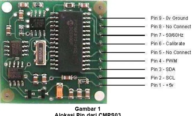
Spesifikasi untuk modul CMPS03 – Devantech Magnetic Compass, yaitu: - Catu daya : +5 VDC,
- Konsumsi arus : 15 mA,
- Antarmuka : I2C atau PWM, - Akurasi : 3-4 derajat, - Resolusi : 0,1 derajat,
- Waktu konversi : 40ms atau 33,3ms dapat dipilih,
- Telah dikalibrasi pada daerah dengan sudut inklinasi 67 derajat.
Gambar 1 Alokasi Pin dari CMPS03
Application note Halaman 2
A
dapun blok diagram sistem secara keseluruhan adalah sebagai berikut:Gambar 2 Blok Diagram AN-09
H
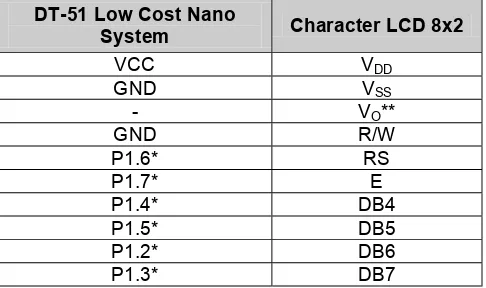
ubungan antaramodul-modul tersebut adalah sebagai berikut:DT-51 Low Cost Nano * Pin ini tidak mutlak dan dapat diganti pin lain dengan cara mengubah program
Tabel 1
Hubungan DT-51 Low Cost Nano System dengan CMPS03 secara I2C dan PWM
DT-51 Low Cost Nano
System Character LCD 8x2
VCC VDD * Pin ini tidak mutlak dan dapat diganti pin lain dengan cara mengubah program
** Pin VO dihubungkan ke resistor variabel seperti pada Gambar 3
Tabel 2
Hubungan DT-51 Low Cost Nano System dengan Character LCD 8x2
Gambar 3
Rangkaian Kontras untuk Character LCD 8x2
CMPS03 DT-51 Low Cost Nano
System
Application note Halaman 3 Selain mengikuti tabel hubungan di atas, buatlah rangkaian jumper seperti pada Gambar 4. Lalu pada saat menggunakan komunikasi I2C, hubungkan pin 2 & 4 serta pin 1 & 3 dari JP1 (Gambar 4) untuk memberi resistor pullup 1k ohm pada jalur SCL & SDA. Sedangkan pada saat menggunakan metode PWM, hubungkan pin 3 & 5 serta 4 & 6 dari JP1 (Gambar 4) untuk memberi resistor pullup sebesar 47k ohm pada jalur SCL & SDA.
Gambar 4
Rangkaian Jumper untuk Pemilihan Resistor Pullup pada Jalur SCL & SDA
Lepaslah AT89C2051 dari board DT-51 Low Cost Nano System. Dan programlah i2c_final.hex (untuk metode komunikasi I2C) atau pwm_final.hex (untuk metode PWM) ke dalam mikrokontroler AT89C2051 menggunakan TOP2004 Universal Programmer atau DT-HiQ Programmer atau DT-51 MinSys v3.0 + DT-51 ProgPAL atau divais paralel programmer lain yang mendukung AT89C2051. Pasanglah kembali AT89C2051 yang telah diprogram ke board DT-51 Low Cost Nano System dan berilah catu daya yang sesuai pada rangkaian.
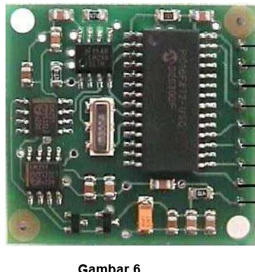
Gambar 5
Rangkaian Tactile Switch untuk Proses Calibrate
Gambar 6
Orientasi CMPS03 yang Menghasilkan Pembacaan Sudut 0º
Application note Halaman 4 Modul CMPS03 telah terkalibrasi di pabriknya namun karena lokasi pabriknya berbeda dengan Indonesia dalam hal sudut inklinasinya, maka modul ini perlu dikalibrasi ulang. Cara mengkalibrasi CMPS03 ada dua cara, yaitu dengan metode I2C atau pin (manual). Dalam aplikasi ini dipilih kalibrasi dengan metode pin (manual) karena dinilai lebih mudah dan efisien. Berikut ini adalah langkah-langkahnya:
1. Gunakan rangkaian tactile switch seperti pada Gambar 5.
2. Posisikan orientasi utara dari CMPS03 (Gambar 6) ke arah utara bumi yang sebenarnya lalu tekan
tactile switch.
3. Putar secara perlahan-lahan sampai orientasi utara dari CMPS03 menuju ke arah timur bumi, lalu tekan tactile switch.
4. Putar secara perlahan-lahan sampai orientasi utara dari CMPS03 menuju ke arah selatan bumi, lalu tekan tactile switch.
5. Putar secara perlahan-lahan sampai orientasi utara dari CMPS03 menuju ke arah barat bumi, lalu tekan tactile switch.
6. Periksalah apakah kompas telah menampilkan arah yang benar sesuai dengan arah sebenarnya. Jika belum sesuai ulangi lagi mulai langkah 1.
7. Jika penunjukan sudah sesuai dengan arah sebenarnya, maka CMPS03 dinyatakan telah terkalibrasi dengan baik.
Kalibrasi ini hanya dilakukan sekali saja, karena hasil dari pengkalibrasian disimpan dalam EEPROM yang terdapat pada CMPS03. Untuk penggunaan selanjutnya (pada lokasi dengan sudut inklinasi sama), tidak perlu dilakukan kalibrasi ulang.
F
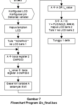
lowchart pogram i2c_final.bas untuk metode I2C adalah sebagai berikut:Application note Halaman 5
P
rogram utama i2c_final.bas akan diproses sebagai berikut:1. Proses yang pertama dilakukan adalah konfigurasi LCD, konfigurasi pin I/O (Sdl & Sca) untuk jalur komunikasi I2C, serta deklarasi variabel yaitu antara lain:
• Addres = variabel I/O untuk menampung alamat register yang akan dibaca pada pemanggilan prosedur Read_compass,
• Value = variabel I/O untuk menampung hasil pembacaan register pada pemanggilan prosedur Read_compass,
• L_value = variabel bertipe byte untuk menampung 8 bit data LSB hasil pembacaan CMPS03,
• A = variabel bertipe word untuk menampung 8 / 16 bit data hasil pembacaan CMPS03,
• Y = variabel bertipe string untuk menampung data yang akan dituliskan ke LCD.
• S = variabel bertipe single untuk menampung data bernilai real yang merupakan hasil bagi dari proses pembagian variabel A.
2. Program akan menghapus tampilan LCD, lalu menampilkan “KOMPAS” pada LCD baris 1.
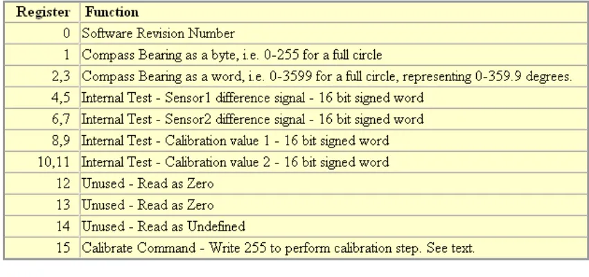
3. Setelah itu dilakukan pembacaan data pada register 2 dan 3 dari modul CMPS03 (Tabel 3) menggunakan prosedur Read_compass. Lalu hasil pembacaan tersebut diletakkan pada variabel A (data dari register 2 – MSB) dan L_value (data dari register 3 – LSB).
4. Program melakukan pengeseran nilai dalam variabel A sebanyak 8 bit ke kiri. Lalu variabel A di-OR-kan dengan variabel L_value dan hasilnya disimpan ke dalam variabel A.
5. Variabel A dibagi dengan 10 dan hasil baginya disimpan ke dalam variabel S. Lalu dengan menggunakan fungsi FUSING, dilakukan pengubahan format data dari real (variabel S) ke dalam bentuk string dan disimpan ke dalam variabel Y.
6. Tampilan LCD pada baris 2 dihapus, lalu ditulisi data hasil pembacaan kompas (data dari variabel Y). 7. Tunggu selama 1 detik lalu kembali ke langkah .
Tabel 3
Alokasi Internal Register CMPS03
P
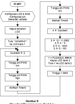
rogram pwm_final.bas secara garis besar akan diproses sebagai berikut:1. Proses yang pertama dilakukan adalah konfigurasi LCD (alokasi pin dan ukuran LCD); konfigurasi Timer0 (mode 1 dan gate-internal); konfigurasi pin I/O (input sinyal PWM); serta deklarasi variabel yaitu antara lain:
• A = variabel bertipe word untuk menampung 16 bit data Timer0 yang merupakan hasil pembacaan CMPS03 secara PWM,
• Y = variabel bertipe string untuk menampung data yang akan dituliskan ke LCD.
• S = variabel bertipe single untuk menampung data bernilai real yang merupakan hasil pengolahan data dari variabel A.
Application note Halaman 6 3. Setelah itu program mengisi register Timer0 dengan data bernilai 0. Lalu menunggu perubahan transisi
naik pada pin input sinyal PWM. Setelah terdeteksi perubahan tersebut Timer0 diaktifkan, lalu menunggu lagi pin PWM berubah menjadi logika 0 dan kemudian mematikan Timer0.
4. Program membaca data dari register Timer0 dan diletakkan ke dalam variabel A.
5. Program melakukan normalisasi data hasil pengukuran Timer0 (variabel A) disesuaikan dengan nilai crystal
yang digunakan mikrokontroler dan hasilnya disimpan ke dalam variabel S. Lalu variabel S dikurangi dengan nilai offset yaitu 1000µs dan kemudian dibagi 100.
6. Lalu dengan menggunakan fungsi FUSING, dilakukan pengubahan format data dari real (variabel S) ke dalam bentuk string dan disimpan ke dalam variabel Y.
7. Tampilan LCD pada baris 2 dihapus, lalu ditulisi data hasil pembacaan kompas (data dari variabel Y). 8. Tunggu selama 1 detik lalu kembali ke langkah .
F
lowchart pogram pwm_final.bas untuk metode PWM adalah sebagai berikut:
Gambar 8
Flowchart Program pwm_final.bas
Catatan:
Pada metode PWM akan diperoleh pembacaan sudut maksimum adalah 357 derajat bukan 359 derajat, hal ini karena pada program pwm_final.bas belum diberi “fiddle factor” yang berguna untuk mengurangi selisih antara modul CMPS03 dan pengukuran / osilator mikrokontroler.
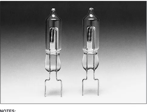
FLAME SENSOR
UV TRON
®R2868
Subject to local technical requirements and regulations, availability of products included in this promotional material may vary. Please consult with our sales office.
Information furnished by HAMAMATSU is believed to be reliable. However, no responsibility is assumed for possible inaccuracies or omissions.
Specifications are subjected to change without notice. No patent rights are granted to any of the circuits described herein. © 1997 Hamamatsu Photonics K. K.
Quick Detection of Flame from Distance,
Compact UV Sensor with High Sensitivity and Wide Directivity,
Suitable for Flame Detectors and Fire Alarms.
Hamamatsu R2868 is a UV TRON ultraviolet detector that makes use of the photoelectric effect of metal and the gas multiplication effect. It has a narrow spectral sensitivity of 185 to 260 nm, being completely insensitive to visible light. Unlike semiconductor detectors, it does not require optical visible-cut filters, thus making it easy to use.
In spite of its small size, the R2868 has wide angular sensitivity (directivity) and can reliably and quickly detect weak ultraviolet radiations emitted from flame due to use of the metal plate cathode (eg. it can detect the flame of a cigarette lighter at a distance of more than 5 m.).
The R2868 is well suited for use in flame detectors and fire alarms, and also in detection of invisible discharge phenomena such as corona discharge of high-voltage transmission lines.
APPLICATIONS
●Flame detectors for gas/oil lighters and matches
●Fire alarms
Spectral Response 185 to 260 nm
Window Material UV glass —
Weight Approx. 1.5 g
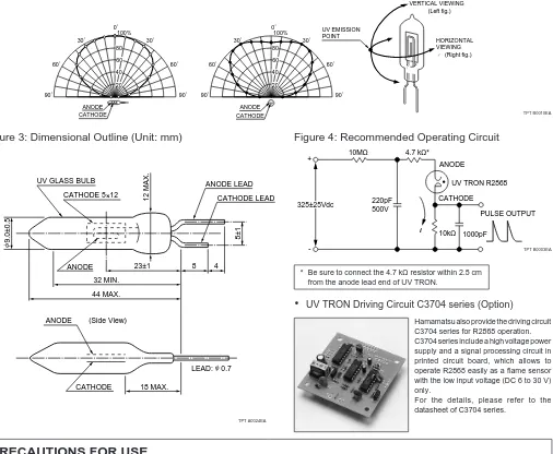
Dimensional Outline See Fig. 3 —
MAXIMUM RATINGS
Parameters Rating Units
Supply Voltage 400 Vdc
Peak Current 1) 30 mA
Average Discharge Current 2) 1 mA
Operating Temperature -20 to +60 °C
CHARACTERISTICS (at 25°C)
Parameters Rating Units
Discharge Starting Voltage (with UV radiation) 280 Vdc Max.
Recommended Operating Voltage 325±25 Vdc
Recommended Average Discharge Current 100 µA
Background 3) 10 cpm Max
Sensitivity 4) 5000 cpm Typ.
NOTES:
1) This is the maximum momentary current that can be handled if its full width at half maximum is less than 10 µs.
2) If the tube is operated near this or higher, the service life is noticeably reduced. Use the tube within the recommended current values.
3) Measured under room illuminations (approximately 500 lux) and recommended operating conditions. Note that these values may increase if the following environmental factors are present.
1. Mercury lamps, sterilization lamps, or halogen lamps are located nearby. 2. Direct or reflected sunlight is incident on the tube.
3. Electrical sparks such as welding sparks are present. 4. Radiation sources are present.
5. High electric field (including static field) generates across the tube. 4) These are representative values for a wavelength of 200 nm and a light input
of 10 pW/cm2. In actual use, the sensitivity will vary with the wavelength of the
ultraviolet radiation and the drive circuitry employed.
Figure 1: UV TRON’s Spectral Response and Various Light Sources
TPT B0009EA
200 300 400 500 600 700 800 900
FLAME SENSOR
UV TRON
®R2868
HAMAMATSU PHOTONICS K.K., Electron Tube Center
314-5, Shimokanzo, Toyooka-village, Iwata-gun, Shizuoka-ken, 438-0193, Japan, Telephone: (81)539/62-5248, Fax: (81)539/62-2205,
U.S.A.: Hamamatsu Corporation: 360 Foothill Road, Bridgewater, N.J. 08807-0910, U.S.A., Telephone: (1)908-231-0960, Fax: (1)908-231-1218 Germany: Hamamatsu Photonics Deutschland GmbH: Arzbergerstr. 10, D-82211 Herrsching am Ammersee, Germany, Telephone: (49)8152-375-0, Fax: (49)8152-2658
France: Hamamatsu Photonics France S.A.R.L.: 8, Rue du Saule Trapu, Parc du Moulin de Massy, 91882 Massy Cedex, France, Telephone: (33)1 69 53 71 00, Fax: (33)1 69 53 71 10
United Kingdom: Hamamatsu Photonics UK Limited: Lough Point, 2 Gladbeck Way, Windmill Hill, Enfield, Middlesex EN2 7JA, United Kingdom, Telephone: (44)181-367-3560, Fax: (44)181-367-6384 North Europe: Hamamatsu Photonics Norden AB: Färögatan 7, S-164-40 Kista, Sweden, Telephone: (46)8-703-29-50, Fax: (46)8-750-58-95
Italy: Hamamatsu Photonics Italia S.R.L.: Via Della Moia, 1/E, 20020 Arese, (Milano), Italy, Telephone: (39)2-935 81 733, Fax: (39)2-935 81 741
Figure 3: Dimensional Outline (Unit: mm) Figure 4: Recommended Operating Circuit
* Be sure to connect the 4.7 kΩ resistor within 2.5 cm from the anode lead end of UV TRON.
• UV TRON Driving Circuit C3704 series (Option)
Hamamatsu also provide the driving circuit C3704 series for R2868 operation. C3704 series include a high voltage power supply and a signal processing circuit in printed circuit board, which allows to operate R2868 easily as a flame sensor with the low input voltage (DC 6 to 30 V) only.
For the details, please refer to the datasheet of C3704 series.
PRECAUTIONS FOR USE
• Ultraviolet Radiation
The UV TRON itself emits ultraviolet radiation in operation. When using two or more UV TRONs at the same time in close position, care should be taken so that they do not optically interfere with each other.
• Vibration and Shock
The UV TRON is designed in accordance with the standards of MIL-STD-202F (Method 204D/0.06 inch or 10g, 10- 500Hz, 15 minutes, 1 cycle) and MIL-STD-202F (Method 213B/100g, 11ms, Half-sine, 3 times). However, should a strong shock be sustained by the UV TRON (e.g. if dropped), the glass bulb may crack or the internal electrode may be deformed, resulting in deterioration of electrical characteristics. So extreme care should be taken in handling the tube.
• Polarity
Connect the UV TRON with correct polarity. Should it be connected with reverse polarity, operating errors may occur.
WARRANTY.
UV TRON
®DRIVING CIRCUIT
C3704 SERIES
Compact, Lightweight, Low Current Consumption, Low Cost
Operates as High Sensitivity UV Sensor with UV TRON
Suitable for Flame Detectors and Fire Alarms
Hamamatsu C3704 series UV TRON driving circuits are low current consuming, signal processing circuits for the UV TRON, well known as a high sensitivity ultraviolet detecting tube. The C3704 series can be operated as a UV sensor by connecting the UV TRON and applying DC low voltage, as they have both a high-voltage power supply and a signal processing circuit on the same printed circuit board.
Since background discharges of the UV TRON caused by natural excitation lights (such as a cosmic ray, scattered sunlight, etc.) can be cancelled in the signal processing circuit, the output signals from the C3704 series can be used without errors. When the high sensitivity sensor “UV TRON R2868” (sold separately) is used, the flame from a cigarette lighter (flame length: 25mm) can be detected even from a distance of more than 5m.
APPLICATIONS
●Flame detectors for gas and oil lighters
●Fire alarms Output signal ... Open collector Output (50 V, 100 mA Max.) 10 ms width pulse output (Note : 1) UV TRON supply voltage ... DC 350 V (Note : 2) Quenching time ... Approx. 50 ms Operating temperature ... -10 to +50°C (with no condensation) Suitable UV TRON ... Low voltage operation UV TRON (such as R2868)
C3704 C3704-02 C3704-03
Input Voltage 10 to 30 Vdc 5Vdc ± 5% 6 to 9 Vdc Current consumption 3 mA Max. 300µA Max. 300µA Max.
Note 1: The output pulse width can be extended up to about 100s by adding a capacitor to the circuit board.
Note 2: Since the output impedance of this power supply is extremely high, an ordinary voltmeter cannot be used. Use a voltmeter that has an input impedance of more than 10 GΩ.
Subject to local technical requirements and regulations, availability of products included in this promotional material may vary. Please consult with our sales office.
Information furnished by HAMAMATSU is believed to be reliable. However, no responsibility is assumed for possible inaccuracies or omissions.
Specifications are subjected to change without notice. No patent rights are granted to any of the circuits described herein. © 1997 Hamamatsu Photonics K. K.
TPT A0024EA
Figure 1: Dimensional Outline (Unit : mm)
UV TRON
®DRIVING CIRCUIT C3704 SERIES
Figure 2: Schematic Diagram
HAMAMATSU PHOTONICS K.K., Electron Tube Center
314-5, Shimokanzo, Toyooka-village, Iwata-gun, Shizuoka-ken, 438-0193, Japan, Telephone: (81)539/62-5248, Fax: (81)539/62-2205, Telex: 4225-186HAMAHQ
U.S.A.: Hamamatsu Corporation: 360 Foothill Road, Bridgewater, N.J. 08807-0910, U.S.A., Telephone: (1)908-231-0960, Fax: (1)908-231-1218 Germany: Hamamatsu Photonics Deutschland GmbH: Arzbergerstr. 10, D-82211 Herrsching am Ammersee, Germany, Telephone: (49)8152-375-0, Fax: (49)8152-2658
France: Hamamatsu Photonics France S.A.R.L.: 8, Rue du Saule Trapu, Parc du Moulin de Massy, 91882 Massy Cedex, France, Telephone: (33)1 69 53 71 00, Fax: (33)1 69 53 71 10
United Kingdom: Hamamatsu Photonics UK Limited: Lough Point, 2 Gladbeck Way, Windmill Hill, Enfield, Middlesex EN2 7JA, United Kingdom, Telephone: (44)181-367-3560, Fax: (44)181-367-6384 North Europe: Hamamatsu Photonics Norden AB: Färögatan 7, S-164-40 Kista, Sweden, Telephone: (46)8-703-29-50, Fax: (46)8-750-58-95
Italy: Hamamatsu Photonics Italia S.R.L.: Via Della Moia, 1/E 20020 Arese, (Milano), Italy, Telephone: (39)2-935 81 733, Fax: (39)2-935 81 741
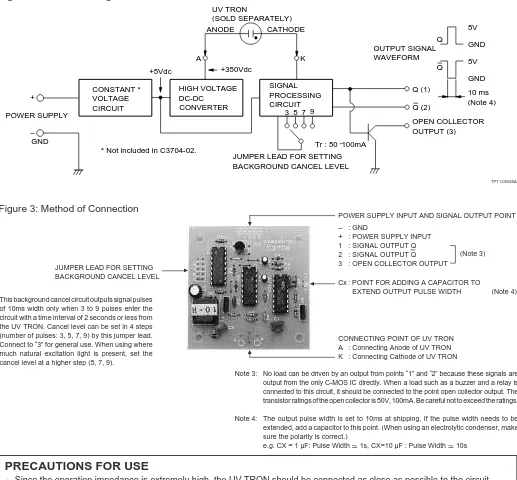
(Note 3) POWER SUPPLY INPUT AND SIGNAL OUTPUT POINT
– : GND
● Since the operation impedance is extremely high, the UV TRON should be connected as close as possible to the circuit board within 5 cm.
● Take care to avoid external noise since a C-MOS IC is used in the circuit. It is recommended that the whole PC board be put in the shield box when it is used.
● To reduce current consumption, oscillating frequency is very low (approx. 20 Hz) in this DC-DC converter. Thus, the output impedance of the high voltage power supply is extremely high. If the surrounding humidity is high, electrical leakage on the PC board surface may lead to a drop in the supply voltage to the UV TRON. This voltage drop may result in lowered detec-tion performance, so a moistureproof material (silicone compound, etc.) should be applied at the connecting point of the UV TRON, etc., if using the unit in a humid environment.
● A model equipped with a flame sensor (R2868) is also available.
Figure 3: Method of Connection
TPT C0004EA
Note 3: No load can be driven by an output from points “1” and “2” because these signals are output from the only C-MOS IC directly. When a load such as a buzzer and a relay is connected to this circuit, it should be connected to the point open collector output. The transistor ratings of the open collector is 50V, 100mA. Be careful not to exceed the ratings.
Note 4: The output pulse width is set to 10ms at shipping. If the pulse width needs to be extended, add a capacitor to this point. (When using an electrolytic condenser, make sure the polarity is correct.)
e.g. CX = 1 µF: Pulse Width 1s, CX=10 µF : Pulse Width 10s
▲
▲ Cx : POINT FOR ADDING A CAPACITOR TO
EXTEND OUTPUT PULSE WIDTH (Note 4)
CONNECTING POINT OF UV TRON A : Connecting Anode of UV TRON K : Connecting Cathode of UV TRON
▲
JUMPER LEAD FOR SETTING BACKGROUND CANCEL LEVEL
▲
This background cancel circuit outputs signal pulses of 10ms width only when 3 to 9 pulses enter the circuit with a time interval of 2 seconds or less from the UV TRON. Cancel level can be set in 4 steps (number of pulses: 3, 5, 7, 9) by this jumper lead. Connect to “3” for general use. When using where much natural excitation light is present, set the cancel level at a higher step (5, 7, 9).
DATA SHEET
Page 1 of The enclosed information is believed to be correct, Information may change ‘without notice’ due to
product improvement. Users should ensure that the product is suitable for their use. E. & O. E.
Revision A 12/12/2006
Sales: 01206 751166 Technical: 01206 835555 Fax: 01206 751188
[email protected] [email protected] www.rapidelectronics.co.uk
Order code Order code Order code
Order code Manufacturer codeManufacturer codeManufacturer codeManufacturer code DescriptionDescriptionDescriptionDescription 78-0792 n/a n/a
TPA81 Infra Red Thermal Sensor
TPA81 Thermopile Array
Technical Specification
Introduction
The TPA81 is a thermopile array detecting infra-red in the 2um-22um range. This is the wavelength of radiant heat. The Pyro-electric sensors that are used commonly in burglar alarms and to switch on outside lights, detect infra-red in the same waveband. These Pyro-electric sensors can only detect a change in heat levels though - hence they are movement detectors. Although useful in robotics, their applications are limited as they are unable to detect and measure the temperature of a static heat source. Another type of sensor is the thermopile array. These are used in non-contact infra-red thermometers. They have a very wide detection angle or field of view (FOV) of around 100° and need either shrouding or a lens or commonly both to get a more useful FOV of around 12°. Some have a built in lens. More recently sensors with an array of thermopiles, built in electronics and a silicon lens have become available. This is the type used in the TPA81. It has a array of eight thermopiles arranged in a row. The TPA81 can measure the temperature of 8 adjacent points simultaneously. The TPA81 can also control a servo to pan the
module and build up a thermal image. The TPA81 can detect a candle flame at a range 2 metres (6ft) and is unaffected by ambient light!
Spectral Response
The response of the TPA81 is typically 2µm to 22µm and is shown below:
Field of View (FOV)
TPA81 Infra Red Thermal Sensor
The typical field of view of the TPA81 is 41° by 6° making each of the eight pixels 5.12° by 6°. The array of eight pixels is orientated along the length of the PCB - that's from top to bottom in the diagram below. Pixel number one is nearest the tab on the sensor - or at the bottom in the diagram below.
Sensitivity
Here's some numbers from one of our test modules:
For a candle, the numbers for each of the eight pixels at a range of 1 meter in a cool room at 12°C are: 11 10 11 12 12 29 15 13 (All °C)
You can see the candle showing up as the 29°C reading. At a range of 2 meters this reduces to 20°C - still around 8° C above ambient and easily
detectable. At 0.6 meter (2ft) its around 64°C. At 0.3 meter (1ft) its 100°C+.
In a warmer room at 18°C, the candle measures 27°C at 2 meters. This is because the candle only occupies a small part of the sensors field of view and the candles point heat source is
added to the back ground ambient - not swamped by it. A human at 2 meters will show up as around 29°C with a background 20°C ambient.
The following is a snapshot of our test program. It displays a 32x8 bitmap produced by using a servo to pan the
sensor. If you want a copy of this windows based program, its here, but you will need an RF04/CM02 to connect
the TPA81 to your PC. Here you can see a candle flame about a meter away showing up as the bright spot.
Connections
All communication with the TPA81 is via the I2C bus. If you are unfamiliar with the I2C bus, there is a tutorial
which will help. The TPA81 uses our standard I2C 5 pin connection layout. The "Do Not Connect" pin should be left unconnected. It is actually the CPU MCLR line and is used once only in our workshop to program the
PIC16F88 on-board after assembly, and has an internal pull-up resistor. The SCL and SDA lines should each have a pull-up resistor to +5v somewhere on the I2C bus. You only need one pair of resistors, not a pair for every
module. They are normally located with the bus master rather than the slaves. The TPA81 is always a slave - never a bus master. If you need them, I recommend 1.8k resistors. Some modules such as the OOPic already have pull-up
TPA81 Infra Red Thermal Sensor
resistors and you do not need to add any more. A servo port will connect directly to a standard RC servo and is powered from the modules 5v supply. We use an HS311. Commands can be sent to the TPA81 to position the servo, the servo pulses are generated by the TPA81 module.
Registers
The TPA81 appears as a set of 10 registers.
Register Read Write
Only registers 0, and 1 can be written to. Register 0 is the command register and is used to set the servo position and also when changing the TPA81's I2C address. It cannot be read. Reading from register 0 returns the TPA81 software revision. Writing to register 1 sets the servo range - see below. It cannot be read back, reading register 1 reads the ambient temperature.
There are 9 temperature readings available, all in degrees centigrade (°C). Register 1 is the ambient temperature as measured within the sensor. Registers 2-9 are the 8 pixel temperatures. Temperature acquisition is continuously performed and the readings will be correct approx 40mS after the sensor points to a new position.
Servo Position
Commands 0 to 31 set the servo position. There are 32 steps (0-31) which typically represent 180° rotation on a Hitec HS311 servo. The calculation is SERVO_POS*60+540uS. So the range of the servo pulse is 0.54mS to
TPA81 Infra Red Thermal Sensor
2.4mS in 60uS steps. Writing any other value to the command register will stop the servo pulses.
Command
Action
Decimal Hex
0 0x00 Set servo position to minimum
nn nn Set servo position
31 0x1F Set servo position to maximum
160 0xA0 1st in sequence to change I2C address
165 0xA5 3rd in sequence to change I2C address
170 0xAA 2nd in sequence to change I2C address
Firmware Version 6 or higher.
As from Version 6 (March 2005) we have added a new write only register (register 1) to allow you to vary the range of the servo stepping. It defaults to the same 180 degree range on a Hitec HS311 servo as earlier versions. You can write values from 20 to 120 to the range register. If you attempt to write a value less than 20, it will be set to 20. If you attempt to write a value greater than 120, it will be set to 120. The calculation for the range in uS is ((31*ServoRange)/2). Setting a range of 20 will give a range of (31*20)/2 or 310uS. Setting a range of 120 will give a range of (31*120)/2 or 1860uS. In all cases the available range is centered on the servo's mid position of 1500uS. So in the first example, the 310uS range will be from 1345uS to 1655uS (Or 1.345 to 1.655mS if you prefer). The second example of 1860uS range centered on 1500uS gives a range of 570uS to 2430uS. On power up the range register is set to 120, which give the same range as earlier versions.
Changing the I2C Bus Address
To change the I2C address of the TPA81 you must have only one module on the bus. Write the 3 sequence commands in the correct order followed by the address. Example; to change the address of a TPA81 currently at 0xD0 (the default shipped address) to 0xD2, write the following to address 0xD0; (0xA0, 0xAA, 0xA5, 0xD2 ). These commands must be sent in the correct sequence to change the I2C address, additionally, No other command may be issued in the middle of the sequence. The sequence must be sent to the command register at location 0, which means 4 separate write transactions on the I2C bus. Additionally, there MUST be a delay of at least 50uS between the writing of each byte of the address change sequence. When done, you should label the sensor with its address, if you lose track of the module addresses, the only way to find out what it is to search all the addresses one at a time and see which one responds. The TPA81 can be set to any of eight I2C addresses - 0xD0, 0xD2, 0xD4, 0xD6, 0xD8, 0xDA, 0xDC, 0xDE. The factory default shipped address is 0xD0.
Mechanical Layout
TPA81 Infra Red Thermal Sensor
1
Universitas Kristen Maranatha
BAB I
PENDAHULUAN
Bab ini berisi tentang latar belakang, identifikasi masalah, perumusan
masalah, tujuan, pembatasan masalah, spesifikasi alat, dan sistematika penulisan
laporan tugas akhir.
I.1 Latar Belakang
Semakin berkembangnya suatu negara, maka semakin banyak aplikasi
teknologi yang diterapkan dalam kehidupan sehari-hari. Salah satu bentuk
teknologi yang banyak digunakan adalah bidang robotika. Saat ini penggunaan
teknologi robotika sudah banyak diimplementasikan dalam bidang medis, industri,
militer, pendidikan, otomotif, hiburan, dan bidang-bidang lainnya. Perkembangan
ini jelas terlihat dari jenis, bentuk, serta kegunaan dari robot yang makin banyak
dan beragam. Peningkatan kualitas robot terutama pada sistem kontrolnya akan
semakin meningkatkan kemampuan robot. Seiring berjalannya waktu, Indonesia
sudah mulai aktif dalam perkembangan dunia robot. Hal itu dibuktikan dengan
perlombaan-perlombaan robot baik tingkat lokal maupun internasional. Saat ini,
pemerintah Indonesia meningkatkan peran serta dunia pendidikan khususnya
tingkat Universitas dengan diwadahi dalam KRCI (Kontes Robot Cerdas
Indonesia).
Robot adalah sebuah alat mekanik yang dapat melakukan tugas fisik, baik
menggunakan pengawasan dan kontrol manusia maupun yang dapat memberikan
respon terhadap kondisi lapangan berdasarkan program yang telah didefinisikan.
Robot biasanya digunakan untuk melakukan tugas berat, berbahaya, berulang, dan
kotor. Atau dengan kata lain, robot digunakan untuk meringankan pekerjaan dan
BAB I PENDAHULUAN 2
Universitas Kristen Maranatha
I.2 Identifikasi Masalah
Pada tugas akhir ini, Robot Cerdas Pemadam Api Beroda diberi nama
Robot LADY. Robot LADY ini juga direalisasikan untuk mengikuti KRCI 2009.
Robot LADY menggunakan roda sebagai alat geraknya dengan misi mencari dan
memadamkan api pada arena lapangan. Dalam mencari dan memadamkan api di
suatu arena lapangan dengan peta tertentu diperlukan kecepatan dan kemampuan
robot dalam bernavigasi dan bermanuver.
I.3 Perumusan Masalah
Perumusan masalah untuk merealisasikan Robot Cerdas Pemadam Api
Beroda (Robot LADY) yaitu :
1. Bagaimana mendesain dan merakit Robot LADY agar dapat bermanuver dan
bernavigasi sehingga dapat mencari dan memadamkan api ?
2. Bagaimana mengontrol Robot LADY dengan menggunakan mikrokontroler
AVR ATMega 16 agar dapat bermanuver dan bernavigasi sehingga dapat
mencari dan memadamkan api ?
I.4 Tujuan
Tujuan yang ingin dicapai pada tugas akhir dalam merealisasikan Robot
Cerdas Pemadam Api Beroda (Robot LADY) yaitu :
1. Mendesain dan merakit Robot LADY agar dapat bermanuver dan bernavigasi
sehingga dapat mencari dan memadamkan api.
2. Mengontrol Robot LADY dengan menggunakan mikrokontroler AVR
ATMega 16 agar dapat bermanuver dan bernavigasi sehingga dapat mencari