SAMPO TURUNEN
PROTECTION OF MICROGRIDS AND DISTRIBUTED
ENERGY RESOURCES BASED ON IEC 61850
Master of Science thesis
Examiner: Prof. Sami Repo
Examiner and topic approved by the Faculty Council of the Faculty of Computing and Electrical Engineering on 3rd February 2016
ABSTRACT
SAMPO TURUNEN: Protection of Microgrids and Distributed Energy Resources based on IEC 61850
Tampere University of Technology Master of Science thesis, 99 pages May 2016
Master's Degree Programme in Electrical Engineering Major: Power Systems and Markets
Examiner: Prof. Sami Repo
Keywords: IEC 61850, distributed energy resources, microgrids, protection, adaptive protection
Microgrids are a potential part of the future smart distribution grid with capability of island operation, envisioned to support the goals of increased use of renewable and distributed energy resources, active consumer participation and improved quality of electricity supply in the future power systems. This thesis examines the implemen-tation of protection systems for microgrids and distributed energy resources using the IEC 61850 standard series. IEC 61850 is one of the core smart grid standards originally developed for substation automation, but extended in its usage to many areas including distributed energy resources.
The main objectives of this thesis are analysing the implementation of microgrid protection, usage of IEC 61850 in distribution applications, and applicability of Multipower test environment of VTT Technical Research Centre of Finland in re-searching these subjects. A literature review of microgrid protection issues and proposed protection schemes as well as an overview of the IEC 61850 standard series and its extensions are presented. An adaptive protection scheme is imple-mented in an example microgrid conguration of the Multipower environment using IEC 61850, and its correct operation veried during islanding and in the case of a communication network failure. Finally, recommendations are given on the future development and research topics of the Multipower environment, including integra-tion of dierent distributed energy resource units from other VTT research areas such as fuel cells and electrical vehicles to the system, studying the usage of dierent networks for communication inside the environment and testing of harmonization between IEC 61850 and other smart grid standards.
ii
TIIVISTELMÄ
SAMPO TURUNEN: Mikroverkkojen ja hajautettujen energiaratkaisujen suojaus IEC 61850 -standardiin perustuen
Tampereen teknillinen yliopisto Diplomityö, 99 sivua
Toukokuu 2016
Sähkötekniikan koulutusohjelma Pääaine: Sähköverkot ja -markkinat Tarkastaja: Prof. Sami Repo
Avainsanat: IEC 61850, hajautetut energiaratkaisut, mikroverkot, suojaus, adaptiivinen suojaus
Mikroverkot ovat osa tulevaisuuden älykästä sähköjakeluverkkoa, jotka tarvittaessa pystyvät itsenäiseen saarekekäyttöön jakeluverkon häiriöiden aikana. Mikroverkot tukevat tulevaisuuden energiajärjestelmän tavoitteita uusiutuvien ja hajautettujen energiaratkaisujen käytön lisäämisessä, kuluttajien aktiivisessa osallistumisessa ja sähkön toimitusvarmuuden ja laadun parantamisessa. Tämä diplomityö käsittelee mikroverkkojen ja hajautettujen energiaratkaisujen IEC 61850 -standardisarjaan pohjautuvien suojausjärjestelmien toteutusta. IEC 61850 on yksi merkittävim-mistä älykkäiden sähköverkkojen tietoliikennestandardeista, jonka soveltamisaluetta on laajennettu alkuperäisestä sähköasemien sisäisestä automaatiosta ja tietoliiken-teestä monille uusille alueille kuten hajautettuun energiantuotantoon.
Työssä esitetään kirjallisuusselvitys mikroverkkojen suojauksen potentiaalisista on-gelmista sekä mahdollisista suojaustavoista, tiivistelmä IEC 61850 -standardisarjan rakenteesta, periaatteista, julkaistuista laajennoksista ja niiden käyttötarkoituk-sista, sekä analysoidaan VTT:n Multipower-testiympäristön soveltuvuutta näiden aihepiirien tutkimukseen. Multipower-ympäristön soveltuvuutta mikroverkkojen suojauksen tutkimukseen testataan toteuttamalla IEC 61850 -pohjainen adaptii-vinen suojausratkaisu testiverkossa. Suojausjärjestelmän oikea toiminta todetaan saarekkeeseen siirtymisen aikana sekä tietoliikennehäiriön tapahtuessa. Multipower-ympäristön tärkeimmiksi tulevaisuuden tutkimuskohteiksi suositellaan VTT:n mui-den tutkimusalueimui-den kuten polttokennojen ja sähköautojen tutkimuslaitteiston liit-tämistä ympäristöön, erilaisten tietoliikenneratkaisujen soveltuvuuden testausta tie-donsiirtoon ympäristön sisällä ja tutkimusta IEC 61850 -standardin yhteensopivuu-desta muiden älykkäiden sähköverkkojen standardien kanssa.
PREFACE
This thesis was written for the Energy systems research area of VTT Technical Re-search Centre of Finland. I'd like to thank my supervisor Dr. Kari Mäki from VTT for this opportunity, and my examiner Prof. Sami Repo for extensive and construc-tive comments during the course of this work. I'd also like to thank Marja-Leena Pykälä from VTT for bringing me up to speed concerning the Multipower test en-vironment and supervising its installations, as well as all my colleagues at VTT Energy systems for a welcoming and relaxed work environment.
I want to thank my family for all their support, and my friends for making my studies and life the joyful adventure it has been. Lastly, thank you Kaisa for being who you are and for the ever-patient encouragement and support.
Espoo, 3.5.2016
iv
TABLE OF CONTENTS
1. Introduction . . . 1
1.1 Background . . . 1
1.2 Scope and structure of the thesis . . . 3
1.3 Relation to the Smart Grid Architecture Model (SGAM) . . . 4
2. Control and management of microgrids . . . 9
2.1 Microgrid structure and properties . . . 9
2.1.1 Main components . . . 10
2.1.2 Potential benets and example market models . . . 15
2.1.3 Properties and testbed experiences . . . 18
2.2 Microgrid islanding and resynchronization principles . . . 19
2.2.1 Controllable elements in the microgrid . . . 20
2.2.2 Islanding . . . 22
2.2.3 Resynchronization to the utility grid . . . 25
3. Microgrid protection . . . 29
3.1 Protection issues of microgrids . . . 32
3.1.1 Eects of DER units on conventional protection . . . 32
3.1.2 Changing grid congurations, islanding and speed requirements . 33 3.1.3 FRT requirements and anti-islanding protection of DER units . . 35
3.2 Available non-adaptive protection schemes . . . 36
3.2.1 Voltage based protection . . . 37
3.2.2 THD based protection . . . 39
3.2.3 Dierential protection . . . 40
3.2.4 Distance protection . . . 41
3.3 Adaptive protection . . . 42
3.3.2 Adaptive over-current protection . . . 44
3.3.3 Adaptive distance protection . . . 45
3.4 An example LV microgrid protection solution . . . 46
4. IEC 61850 in DER applications . . . 51
4.1 IEC 61850 overview . . . 52
4.1.1 Objectives . . . 52
4.1.2 Approach . . . 53
4.1.3 Structure . . . 54
4.1.4 Envisioned benets and current experiences . . . 56
4.2 Information model . . . 56
4.2.1 Logical nodes . . . 58
4.2.2 Data, data attributes and common data classes . . . 60
4.3 Information exchange: ACSI and SCSMs . . . 62
4.3.1 Meta models . . . 62
4.3.2 Information exchange modelling classes . . . 63
4.3.3 Application associations . . . 65
4.3.4 GOOSE messages and sampled values . . . 66
4.3.5 Specic Communication Service Mappings (SCSMs) . . . 68
4.4 IEC 61850 and Distributed Energy Resources . . . 71
5. Case study: Adaptive protection in Multipower test environment . . . 76
5.1 Multipower test environment . . . 76
5.2 Adaptive protection scheme and implementation . . . 78
5.2.1 Test system and desired operation . . . 78
5.2.2 IEC 61850 model . . . 80
5.2.3 Implementation . . . 82
5.3 Test results . . . 84
vi
6. Conclusions . . . 89 Bibliography . . . 91
LIST OF ABBREVIATIONS AND SYMBOLS
ACSI Abstract Communication Service InterfaceAL Application Layer
AVR Automatic Voltage Regulator
CDC Common Data Class
CHP Combined Heat and Power
CIGRE Conseil International des Grands Réseaux Électriques, International Council on Large Electric Systems
CIM Common Information Model
COSEM Companion Specication for Energy Metering
CT Current Transformer
DER Distributed Energy Resources DFT Discrete Fourier Transform
DG Distributed Generation
DMS Distribution Management System
DR Demand Response
DS Distributed Storage
DSO Distribution System Operator EPRI Electric Power Research Institute
FC Functional Constraint
FRT Fault ride-through
GOOSE Generic Object Oriented Substation Event
GSE Generic Substation Event
HIF High Impedance Fault
IEA International Energy Agency
IED Intelligent Electronic Device
IEC International Electrotechnical Commission IEEE Institute of Electrical and Electronics Engineers IGBT Insulated Gate Bipolar Transistor
LAN Local Area Network
LD Logical Device
LN Logical Node
LoM Loss-of-Mains
LTE Long-Term Evolution, 4G standard for high-speed wireless commu-nication
viii
MMS Manufacturing Message Specication
MGCC Microgrid Central Controller
MPPT Maximum Power Point Tracking
OC Overcurrent
OSI Open Systems Interconnection
PCC Point of Common Coupling
PAS Publicly Available Specication
PLL Phase Locked Loop
PUAS Power Utility Automation System
PV Photovoltaics
RES Renewable Energy Source
RTU Remote Terminal Unit
SCADA Supervisory Control and Data Acquisition
SCL Substation Conguration Language
SCR Silicon Controlled Rectiers
SCSM Specic Communication Service Mapping SGAM Smart Grid Architecture Model
SNTP Simple Network Time Protocol
THD Total Harmonic Distortion
TC Technical Committee
TR Technical Report
TS Technical Specication
VSC Voltage Source Converter
VT Voltage Transformer
VTT VTT Technical Research Centre of Finland XMPP Extensible Messaging and Presence Protocol
f frequency H inertia constant P active power Q reactive power R resistance S apparent power U voltage X reactance Z impedance ω angular frequency
1. INTRODUCTION
1.1 Background
Modern society is completely dependent on an uninterrupted supply of electricity. More and more attention is being paid to the security, reliability and quality of power supply while at the same time climate goals are driving investments in new, renew-able energy solutions. These new elements should be integrated to the power system with minimum costs, maximum interoperability and compatibility with widely inte-grated internal energy markets of areas like the European Union [1]. According to the International Energy Agency (IEA), investments in renewable sources of energy increased from $60 billion in 2000 to $250 billion in 2014. Over the period to 2035, IEA estimates total investments in renewables to amount to $6 trillion and a further $7 trillion being spent on transmission and distribution. [2]
While emerging economies have to deal with hugely growing electricity demand, OECD countries are faced with aging infrastructure, wide deployment of distributed energy resources (DER) and integration of often volatile or intermittent renewable energy sources. To respond to these challenges, the existing electricity grids are being developed from passive networks to active smart grids. The European Technology Platform of Smart Grids denes smart grid as "an electricity network that can intel-ligently integrate the actions of all users connected to it - generators, consumers and those that do both - in order to eciently deliver sustainable, economic and secure electricity supplies." [3] European smart grid projects launched from 2002 up to 2014 totalled $3.15 billion in investments across 459 projects [4]. The biggest changes are happening at the distribution level, where integration of distributed generation, en-abling of local energy demand management and smart metering, and adoptation of technologies from transmission grids are creating a whole new set of requirements for the power system and especially the communication system associated with it. One of the promising smart grid concepts in achieving the aforementioned goals is to take a system approach which views local generation and associated loads as a
sub-1.1. Background 2
system or a microgrid. A microgrid can be dened as "a part of smart distribution grid with an island operation capability" [5], i.e. if needed it can operate indepen-dently without utility network connection. Microgrids are envisioned to be viewed from the outside as a single controllable entity, and be able to support the goals of future power systems in many possible ways. These include for example realizing an energy-independent area, a platform for sharing energy resources between owners, oering support for utility networks during normal operation or fault situations, or oering aggregated demand response capabilities for balancing purposes of market operators or electricity producers among others.
The protection of electricity networks is a foundational part of safe usage and op-eration of the power system. With these new concepts, the traditional control and protection systems face new challenges that need to be addressed in order to real-ize the vision of future power systems. Distributed and power electronic interfaced generation, diering characteristics of distribution and transmission networks and islanded use of microgrids all pose issues that must be considered in the protection systems of these new structures.
These developments also raise the need for standardization to manage the increas-ing number of interconnected systems and entities operatincreas-ing in the power system domain. Standardization of smart grids is a key component in achieving the goal of interoperability internally in systems with a wide variety of functions as well as between them for the large-scale integration of energy systems. The International Electrotechnical Commission (IEC), a leading international electrical standards de-velopment organization, published the IEC Smart Grid Standardization Roadmap in 2010 [6] for coordination of its standardization work. In this roadmap a num-ber of core standards are dened, with special relevancy to nearly all smart grid applications. One of these core standards dening the smart grid communication systems is the IEC 61850 standard family "Communication Networks and Systems for Power Utility Automation". With important application areas starting from the original scope of substation automation to new application areas like hydro power and distributed energy resources, the standard is designed to adopt state-of-the-art protocols and provide also guidance in areas like engineering and maintenance. The IEC 61850 is therefore also an integral part of modern distribution grid applications, and a focus point in a lot of research related to the eld.
1.2 Scope and structure of the thesis
This thesis has been written for the VTT Technical Research Centre of Finland in association with the installation of a new IEC 61850 -based control and protec-tion system for the Multipower test environment for distributed energy resources in Espoo, Finland. The main objectives and research questions are:
• How can the protection of microgrids be implemented using IEC 61850? • How widely can IEC 61850 be applied in distribution applications, what is the
current state of the standard and what is being developed?
• How applicable is the Multipower laboratory environment in researching these
subjects and what should be developed?
The new installations as well as the envisioned future state and usage of the test environment as a standard-based, multifunctional and exible testbed are the de-ciding factors for the scope of this thesis. The chosen approach to the wide topic of microgrids and distributed energy resources is from a technical requirement and capability aspect, and more specically as relevant to the widening scope of the IEC 61850 standard series. Solutions and concepts based on communication are of specic interest, since in these solutions IEC 61850 has the most relevance. The chosen point of view is also guided by the approach of the standard series: instead of examining ownerships, market participants or operators, the area of interest is in the operation and communication between devices in realizing wanted power system functions, with focus on protection systems. Business mechanisms, energy market participation models and detailed economical cost-benet analyses of dierent solu-tions, while vitally important to real world microgrids, are not covered by IEC 61850 and therefore are not the focus of this thesis.
In the next section, the focus of this work is presented in context of the European Smart Grid Architecture Model (SGAM) framework. In Chapter 2, the general structure and properties of microgrids are examined, as well as principles for suc-cessful islanding and resynchronization to the utility grid. In Chapter 3, protection issues of microgrids as well as proposed solutions are reviewed, with a special focus on adaptive protection. Chapter 4 presents an overview of the IEC 61850 standard series, its information model and information exchange mechanisms, as well as its
1.3. Relation to the Smart Grid Architecture Model (SGAM) 4
usage in DER applications. In Chapter 5 the Multipower test environment is in-troduced, and a simple test conguration is used to prove the adaptive protection capabilities of the new protection and control system installed. Finally, conclusions are presented in Chapter 6.
1.3 Relation to the Smart Grid Architecture Model (SGAM)
In March 2011, the European Commission issued the M\490 mandate for Smart Grid standardization [7]. One of the key deliverables mentioned in the mandate was "A technical reference architecture, which will represent the functional informa-tion data ows between the main domains and integrate many systems and subsys-tems architectures." To fulll this requirement the Reference Architecture Working Group CG/RA) was formed under the Smart Grid Coordination Group (SG-CG) established by the European standardization organizations CEN, CENELEC and ETSI. The reference architecture is presented in the form of a technical report [8], and consists of four main components: the European Conceptual Model, the Smart Grid Architecture Model (SGAM) Framework, Architecture Viewpoints and SGAM Methodology. The European Conceptual Model is an evolution of the NIST Smart Grid Conceptual Model presented in [9] with EU specic requirements, most important being the integration of Distributed Energy Resources (DER). It acts as an overall high-level model that describes the main actors of the Smart Grid and their main interactions, while the SGAM framework along with the dierent view-points allow various levels of description of desired smart grid aspects from top-level to more detailed views. The SGAM methodology describes using the SGAM Frame-work in assessing smart grid use cases and how they are supported by standards, allowing standards gap analysis.
The SGAM Framework is a three dimensional model consisting of dened interoper-ability layers on top of the Smart Grid Plane divided to ve domains and six zones, as seen in Figure 1.1. With these components, the SGAM framework aims to pro-vide a mapping and design tool for smart grid use cases, architectures and entities ensuring all necessary levels of interoperability and information management hierar-chy in all relevant smart grid domains are covered. The dierent domains describe the physical electrical energy conversion chain and include
2. Transmission, including infrastructure for transporting electricity over long distances
3. Distribution, including infrastructure for the distribution of energy to cus-tomers
4. DER, including distributed energy resources connected directly to the public distribution grid
5. Customer Premises, including both end users and producers of electricity in industrial, commercial and home facilities.
Figure 1.1 SGAM Framework [8]
Zones on the other hand represent the dierent hierarchical levels of power system management and are based on the concepts of aggregation and functional separation. Dened zones are
1. Process, consisting of transformation and movement of energy and the physical power system equipment directly involved
1.3. Relation to the Smart Grid Architecture Model (SGAM) 6
2. Field, consisting of the secondary process equipment used to protect, control and monitor the primary power system process
3. Station, consisting of the areal aggregation of eld level data and functions 4. Operation, consisting of the overall power system control operation in the
respective domain
5. Enterprise, consisting of the commercial and organizational processes, services and infrastructures of involved enterprises
6. Market, consisting of the market operations possible along the energy conver-sion chain spanning several organizations.
Interoperability is seen as a key enabler of smart grid. It is described in [8] as "the ability of two or more devices from the same vendor, or dierent vendors, to exchange information and use that information for correct cooperation". Interoper-ability requirements in SGAM are grouped into ve layers. Inspecting and dening interoperable functionality in all layers is meant to ensure compatibility in all levels of system interactions.
1. Business Layer represents the economic and regulatory structures and policies as well as business models, capabilites and processes of the smart grid actors involved.
2. Function Layer describes functions, services and their relationships indepen-dent from actors or physical implementations.
3. Information Layer describes the information being used and exchanged be-tween functions, services and components, as well as the underlying data mod-els for this information.
4. Communication Layer describes the protocols and mechanisms used for the exchange of information dened in the information layer.
5. Component Layer includes the physical components, actors and applications participating in the selected functionality.
As stated in the previous section the scope of this thesis is limited to microgrid en-vironments and distributed energy resources, with specic focus on the IEC 61850 standard series. In Figure 1.2, this scope is presented as relevant areas of the SGAM framework. Microgrids as a part of the future smart distribution system cover the domains of Distribution, DER and Customer premises, in a very interconnected way. While market participation and regulatory framework of operation are very important questions in the realization of microgrids, this thesis focuses on the tech-nical aspects as related to the control and protection of these systems. Therefore the zones of interest include Process, Field, Station, Operation and to some extent technical systems at the Enterprise zone, but largely exclude the commercial and or-ganizational processes at the Market zone. All of the dened interoperability layers are relevant to the chosen focus. Although the wide questions of business models, policies, and regulatory structures examined at the Business Layer fall outside the scope of this thesis, the objectives, requirements and needs for the functions at the Function layer are determined at the Business layer. Function, Information and Communication Layers are all associated with IEC 61850, and Component Layer is naturally of signicance when implementing real systems such as the Multipower test environment presented in Chapter 5.
1.3. Relation to the Smart Grid Architecture Model (SGAM) 8
2. CONTROL AND MANAGEMENT OF
MICROGRIDS
2.1 Microgrid structure and properties
Microgrid as a term does not have a single strict denition that is used and accepted everywhere. Lasseter described the MicroGrid concept in 2002 as "a cluster of loads and microsources operating as a single controllable system that provides both power and heat to its local area" that could be thought as a controlled cell of the power system [10]. The European Technology Platform SmartGrids dened microgrids in 2006 as low-voltage networks with distributed generation (DG) sources, local stor-age devices and controllable loads that have the ability to operate in islanded mode when needed in addition to while being connected to the distribution network [11]. Laaksonen raises this ability as the key property of the microgrid, with a general denition of "a part of smart distribution grid with an island operation capabil-ity" [5]. This denition has been chosen for this thesis since island operation is a unique property of microgrids compared to modern active distribution networks, which otherwise can share many of the same properties.
Microgrids aren't necessarily restricted to the low-voltage (LV) level either, but can consist of a medium-voltage (MV) feeder or even all MV feeders of a high-voltage/medium-voltage (HV/MV) substation. [5, 12] They are seen as a major building block in the distribution system of the future, with potential benets in-cluding enhanced local reliability, improved energy eciency and power quality, and reduced distribution network losses and capacity requirements among others [5, 13, 14]. In this section the main components and structure of microgrids is presented, along with the special properties they give to grid operation and control compared to conventional distribution systems.
2.1. Microgrid structure and properties 10
2.1.1 Main components
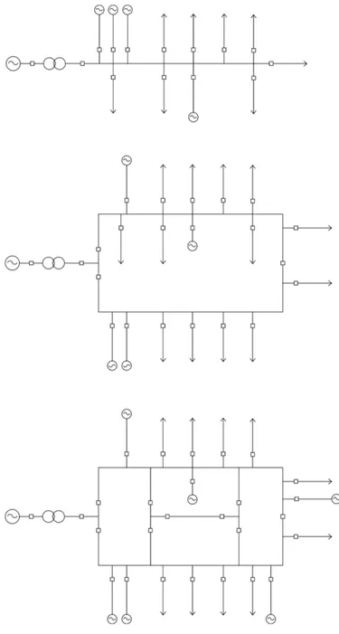
Although microgrids can take several forms with varying sizes and locations in the electrical system, the main components forming the microgrid remain largely the same. First of all a combination of Distributed Energy Resources (DER) is integral to the functioning of a microgrid. They are small sources of energy located at or near the point of use. This can mean either distributed generation (DG) units, distributed storage (DS) systems, or a hybrid combination of both. Typical DG technologies include photovoltaics (PV), wind power, fuel cells, microturbines and reciprocating internal combustion engines with generators. Some of these technologies like micro-turbines or fuel cells can provide combined heat and power (CHP) which increases their overall eciency. Most of the technologies used connect to the grid via a power electronic interface, consisting of either a DC/AC inverter or an AC/DC rectier and a DC/AC inverter. [15] These converters can provide an additional layer of con-trol and protection to the unit [16]. In addition to DER units, demand response (DR) technologies, also referred to as demand side integration (DSI) or demand side management (DSM), can provide additional exibility to the microgrid by providing controllable or dispatchable loads in exchange for remuneration to the customer. Second, the physical network connecting DER and customer loads to each other as well as to the utility grid is needed. Three basic topologies of the grid include radial, ring and mesh congurations, as shown in Figure 2.1. The structural topology of the network may dier from the topology actually used during operation, as discussed below. The connection point between the microgrid and utility network, often referred to as the point of common coupling (PCC), is of specic interest since it connects the microgrid to the rest of the distribution network. PCC is the boundary where a microgrid can be isolated if needed, usually located downstream of the utility transformer. It can also be seen as the limit where control responsibility moves from the utility to the microgrid owner. The technical details of measurements, control and protection needed at the PCC will be discussed in Sections 2.2.2 and 3.1.2. Radial conguration is the simplest topology, consisting of one main line (or multiple parallel lines) with loads and DER units connected to the main line as branches. This simplies the technical implementation of protection and control of the microgrid. It is even possible to connect the DER units close to the transformer and keep the power and current ows in one direction in all scenarios, keeping the control and protection located in the substation. Radial topology is the most common structure
Figure 2.1 Dierent grid topologies from top to bottom: radial, ring and meshed networks.
in the current grid, especially in rural areas. Operation-wise distribution networks, with the exception of very few cases in MV networks, are operated radially, even if the actual structural topology is a ring or meshed network. It is also the only topology applicable to LV networks where fuse protection is currently the primary protection equipment, therefore not necessarily requiring new expensive components.
2.1. Microgrid structure and properties 12
Ring conguration consists of lines creating a geometrical loop or ring shape, thus enabling two alternative routes for power ow to any given point of the network. This oers better voltage stability and lower power losses, but also requires a more sophisticated protection system [12]. Ring topology is currently a common network structure in residential areas, but because of the complicated protection needed, it is operated as a radial grid by keeping one disconnector of the ring always open, forming two parallel radial lines. This achieves maximum selectivity by allowing the isolation of a faulty network segment and restoration of supply to all customers behind the faulty area, while maintaining system simplicity.
Mesh conguration further increases redundancy by oering multiple alternative connections to all network nodes. It provides the most exibility, but also makes operation and protection of the microgrid challenging. Additional power lines and breaker equipment also make mesh congurations the most expensive option. As with ring topology, only some of the possible network congurations might be used. [12]
DER penetration and its passive tolerance in the grid do not alone fulll the charac-teristics of a microgrid [17]. The third main component of a microgrid is an advanced control and monitoring system that provides active supervision, control and opti-mization inside the grid. A microgrid operator serves multiple economic, technical and environmental aims: it is an aggregator of small generators, a network service provider, a load controller and an emission regulator at the same time. Capability of handling conicting interests of dierent stakeholders and arriving at an optimal operation decision is an important characteristic of microgrid control. [13] The mi-crogrid management system can be seen as a transition of distribution management system (DMS) functionality to the lower levels of the distribution network, and could be responsible for these lower level operations in the hierarchical management of future smart distribution networks [5]. A conceptual structure of a microgrid management system is presented in Figure 2.2. Each DER unit, in addition to having advanced electronic metering capabilities, is equipped with a microsource controller (MC). The MC is an intelligent electronic device (IED) responsible for controlling and monitoring the DER unit, and can be a separate device or a soft-ware implementation in either the DER power electronic interface or the metering unit. Additionally, demand side integration is realized by load controllers (LC) at the customer's point of connection to the grid.
Figure 2.2 Typical microgrid management system [13].
The microgrid central controller (MGCC) acts as the coordinator of the microgrid as well as the main interface between the microgrid and other related actors. Among the most important are the local Distribution System Operator (DSO), possible third party aggregators and the energy markets. The DSO controls the MV side circuit breakers and disconnectors, receives measurements from the MV/LV trans-former and may have IEDs communicating with the MGCC or microgrid IED at the PCC regarding protection, islanding and resynchronization between the microgrid and the utility network. The meter data management system (MDMS) of the DSO collects data from the AMR meters of the microgrid, forwards alarms and relevant measurements to the DMS and correspondingly requests from DMS to the AMR meters. Third party aggregators can act as coordinators and market operators com-bining the microgrid resources and oering them to energy markets or as ancillary services. These functionalities can be achieved through a home or building energy management system (HEMS/BEMS), which aggregates data of single DER units and loads, communicates with higher level systems and optimizes local energy use
2.1. Microgrid structure and properties 14
through resource allocation according to dierent microgrid stakeholders' needs. Distribution of functions and control between the MCs and the MGCC can vary according to the selected control architecture. The main types include centralized, decentralized and distributed control. In centralized control the MGCC takes the main role in the overall optimization of the operations and value of the microgrid, taking into account market prices, grid limitations or service requests from outside the microgrid, and sending control signals to the microsources and controllable loads of the microgrid. Monitoring of the actual active and reactive power of the sources and loads is necessary in order to ensure correct operation. In fully decentralized control, the MCs are given the main responsibility of optimizing their own pro-duction according to local demand and market prices. Certain functions are still centralized, such as load and generation forecasts and security monitoring, but the DER units operate autonomously within given limits without explicit control signals from other sources. Decentralized control is visioned to need only modest commu-nication capabilities compared to a centralized solution, at the cost of local instead of global optimization. Distributed control diers from decentralized architecture in that local controllers communicate with each other in order to form a view of the overall system state that is used on making control decisions. This can include technologies like agent-based control, in which control is achieved through indepen-dent, intelligent agents (like inverters, DGs or loads) and negotiation between them, following the multi-agent system (MAS) theory [18]. Truly distributed systems are however hard to realize in practice without some party acting as a coordinating unit, especially if network state estimation or optimal power ow calculations are needed. In [13], Hatziargyriou recognizes centralized architecture to be applicable in a case where the microgrid is owned by a single entity with a clear goal such as an industry owner trying to minimize operating costs, while decentralized solutions are seen to work best in the case of multiple owners of DG units with diverse needs and goals, like dierent households in a microgrid operated in a market environment. However, in [5] Laaksonen has compiled numerous issues from the grid perspective associated with microgrid concepts without one grid-forming master unit and other grid-following units controlling their output based on reference signals, such as
• Need for additional batteries in the DC-link of the converter-connected DER
units for power balance and voltage control during island operation with con-ventional droop control
• lack of adequate voltage control with Q/U-droops requiring a large amount of
reactive power to control voltage in LV networks
• more required capacity from grid-side converters
• lack of feasible protections system compatible with normal LV networks • synchronized reconnection procedure not possible without communication.
All in all commercial DER units are not currently compliant to the technical re-quirements present in decentralized microgrid operation. This is only natural be-cause there also doesn't exist any national or international specications that would dene these requirements. In the EU project More Microgrids Schwaegerl et al. have visioned the MGCC as the responsible entity for the maximization in micro-grid value, while the MCs perform local optimization in production and transient conditions [17]. In the case of multiple owners of DG units with dierent needs, an energy cooperative or community with centralized control could provide an alterna-tive to decentralized control with more ecient system-wide resource optimization and system management. A 2014 review of microgrid testbeds around the world by Hossain et al. [19] shows a slight bias toward decentralized control methods, with 29 out of the 50 reviewed testbeds categorized as having either a decentralized or agent-based control system. There are locational dierences: North America seems to be especially focused in decentralized systems (15 out of 20 testbeds), while in Japan all 5 testbeds that were categorized had a centralized control system. Micro-grids of the European Union and the rest of the world are almost equally distributed between centralized and decentralized control. In future commercial microgrids the adopted market mechanisms, regulation and grid codes will dictate how dierent parties will operate their available DER resources and what kind of services they can oer [5]. These decisions also have an eect on what kind of control methods will be the most viable and ecient. In the scope of this thesis centralized solutions are of specic interest since communication and therefore related standards are in-herently important to the system, though as said decentralized solutions also have some form of central coordination and communication capabilities as well.
2.1.2 Potential benets and example market models
Microgrid oers potential benets to the microgrid clients, the distribution system operator, possible third party operators and the public sector. The distribution
sys-2.1. Microgrid structure and properties 16
tem operator gets the most benets from the grid stability, reliability and service related factors of microgrids. Local power balancing and demand side management can be used to reduce local deviations or improve stability, or be oered as a grid supporting service. Reliability can be improved inside the microgrid as well as potentially in the nearby utility network, if microgrid can provide support during disturbances by for example load shedding, resulting in lower outage costs. Distri-bution system upgrades due to increased peak power conditions can potentially be postponed if these peaks are reduced through active microgrid management. The development of DMS-like functionality in the microgrid management system can also make it possible for the microgrid operator to take responsibility for end distri-bution and quality of customer supply, with the responsibilities of the DSO ending at the PCC.
For the microgrid clients potential benets include cost reductions, improved power quality and reliability due to smart local resource management. Microgrids can also promote the shift from consumers to prosumers, enabling clients to acquire and integrate their own production more economically. Proper user interfaces can provide more information about the eects of customer decisions, further promoting activity. Local trading or alternatively aggregation in the microgrid level can also make it possible for individuals to participate in electricity markets in an inexpensive way.
Microgids also oer opportunities for 3rd party operators in whole new roles, like providing the microgrid management and maintenance as a service to microgrid clients, backup power and disturbance workforce to the DSO or acting as an ag-gregator, collecting the small-scale DER units and demand response resources and oering them as an entity in the electricity markets or as technical services to the DSO, such as frequency or voltage support. Microgrids can help the public sector in achieving national or international energy goals through increased use of renew-able energy sources, as well as reducing greenhouse gas emissions thorugh eective demand side management.
Some of the benets are shared between multiple stakeholders, and naturally the investment costs as well as possible drawbacks in more complicated system usage need to be taken into account when designing a fair market model between dierent actors in the microgrid environment. In [17] Schwaegerl et al. have identied three typical setups for a microgrid market model: DSO Monopoly, Prosumer Consortium
and Free Market. Finnish legislation eectively prevents a DSO owned and operated microgrid through the electricity market act [20], so only the prosumer consortium and free market models are shortly presented here.
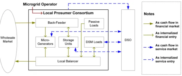
In a prosumer consortium microgrid single or multiple consumers will purchase and operate DER units to minimize their electricity bill or maximize sales revenue from export, as shown in Figure 2.3. A consortium of these prosumers may take the responsibility of microgrid operation and purchase it as a service from a third party provider. Most likely motivated by high retail electricity price or DER nancial support level, this type of microgrid by nature tends to minimize the import from the distribution grid and therefore reduce the revenue of the DSO [17]. Higher power based pricing might be imposed to cover the network upkeeping costs. DSO can inuence the operation of the microgrid by imposing requirements and charges to the DER unit owners, but the consortium makes the operational decisions according to its own optimization goals. A local retail market must be allowed for the internal trading of the consortium.
Figure 2.3 The cash ows of the prosumer consortium microgrid market model [17].
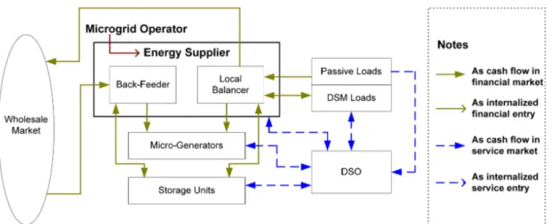
The free market model shown in Figure 2.4 aims at exibly optimizing various motives of dierent stakeholders. The daily operation decisions will be dependent on interest arbitration of all involved parties, and the microgrid central controller (MGCC) plays an important role being simultaneously responsible for local balance, import and export control, technical performance maintenance and emission level monitoring. [17] Ideally this allows the benets of microgrid operation to be split and directed to proper recipients.
2.1. Microgrid structure and properties 18
Figure 2.4 The cash ows of the free market microgrid market model [17].
2.1.3 Properties and testbed experiences
Traditionally, the frequency response of larger power systems is based on rotating masses of turbines and their governors, primarily found in large generation units, that provide essential natural stability to the system. In microgrids the generation is mainly converter-connected, with very few directly connected rotating masses and thus very low inertia. With the addition of possibly slow control signal response of some DG technologies, this creates power balance and voltage control challenges and makes island operation technically demanding. Because of these reasons energy storages are essential to stabilize the microgrid and permit DG units to run at a stable output despite load or primary energy source uctuations. [5] The complete frequency control strategy should exploit cooperatively the capabilities of DG units' active power control, response of storage devices, and load shedding [15]. In addition to the technical control challenges, economical goals of dierent DER operators or things like required heat generation in a CHP unit can cause additional constraints for the usage of DER units.
In smaller microgrids a signicant degree of unbalance may exist due to the presence of single phase loads and DER units. Also a considerable part of the supply within a microgrid can come from non-controllable sources such as wind power units or PV cells. [16] The control strategies for DER units must be designed to work in both grid-connected and islanded operation, and oer sucient regulation of microgrid voltage and frequency during islanded use.
In [12] Soshinskaya et al. have collected experienced problems in real world mi-crogrids, with technical issues divided in technological, dual-mode (island and grid-connected) operation, power and frequency control, and protection and safety issues. Especially fuel cells seem to cause a lot of technological problems, with Utsira Island, Santa Rita Jail and Sendai microgrids all reporting fuel cell related issues. Kythnos microgrid in Greece experienced communication problems in using Wi- and PLC channels due to humidity and rise of system frequency, respectively [21]. Concern-ing dual-mode operation the Bronsbergen microgrid in Netherlands, equipped with two parallel inverter systems, reported islanding detection to be "feasible but not as straigthforward as it would be for a single inverter", underlining the need for further research in the area. Power quality issues were also mentioned, with addi-tional active compensation added in the inverters to reduce high 3rd, 5th and 7th harmonic voltages during islanded mode. [13] The Hachinohe microgrid in Japan reported a 2.6 Hz frequency drop and 6 % voltage drop with 50 kW AC startup, as well as too high negative sequence current caused by phase unbalance. High speed battery inverter control and a negative sequence compensator were used to solve the problems. [22] While technical issues were among the most reported, they have a multitude of potential solutions that already exist or are being researched. Soshin-skaya et al. conclude that apart from the short term problem of the expensiveness of DER units, the greatest barriers to microgrid implementation are related to regula-tion and the market environment: issues regarding bi-direcregula-tional power ow between the microgrid and utility network as well as the ability of local trading. [12]
2.2 Microgrid islanding and resynchronization principles
Previous sections have introduced typical microgrid structures and their main com-ponents, and analysed properties and challenges associated with these new struc-tures. In this section the controllable elements of microgrids are presented, and then special attention is paid to the principles of islanding and resynchronizing pro-cedures of microgrids, since these propro-cedures are the ones with high relevance to the microgrid protection system and the operation of its IEDs. The issues of energy capacity and active power control during islanded operation are highly dependent on the design and implementation of inverter control and therefore not in the focus of this thesis. More on the development of appropriate control methods can be found in e.g. [23], [24] and [25].
2.2. Microgrid islanding and resynchronization principles 20
2.2.1 Controllable elements in the microgrid
A microgrid acts inherently as a connector and service provider for a wide range of dierent energy resources, with varying possibilities for control. The distributed gen-eration (DG) in a microgrid can be divided to intermittent and dispatchable units. Intermittent units, using a renewable energy source (RES) such as wind or the sun as their primary energy source, are limited by the physical nature of this source. Their control is preferably based on maximum power point tracking (MPPT), a strategy used to deliver the maximum power according to the optimal operation condition of the unit's primary energy source at each moment [16]. Furthermore, limiting the production of a RES unit is often undesirable because of the proportionally high investment and very low operating costs of these units. Therefore the desired oper-ation strategy for intermittent RES units can be described as "priority dispatch", meaning their production will not be actively curtailed, limited or otherwise con-trolled by an outside source unless it leads to violation of system constraints, such as line overloads or overvoltage problems. However, the unit can have an indepen-dent reactive power interface decoupled from its active power output, in which case it can participate in the reactive power dispatch of the microgrid. [13] In islanded use it may be desirable to limit changes in the active power. Additionally, if the generation capacity is sucient compared to the load and using the DG unit for active power dispatch allows savings like in the form of smaller energy storages in the system, controlling the output power may be economically benecial due to the reduced investment costs.
Dispatchable DG units on the other hand allow their output power to be controlled externally, through set points provided by a supervisory control system. Typical example of a dispatchable unit is a synchronous generator driven by a reciprocating internal combustion engine, equipped with a governor for speed control and fuel in-ow adjustment, as well as an automatic voltage regulator (AVR). The governor controls the active power, while AVR controls the internal voltage of the synchronous generator, and through that the reactive power output of the unit. [16] While CHP units are often dispatchable in nature, their controllability varies according to the chosen handling of local heat demand: the unit can be heat-driven, electricity-driven, or operated in a hybrid mode [13].
Distributed Storage (DS) units in the microgrid can be operated as a balancing unit in two principally dierent ways. In a load-following scheme the storage acts as a
balancing unit to load or RES production uctuations, charging itself during times of low demand and high production and discharging during high demand to reduce the maximum power required. In the price-following paradigm the storage is used to maximize benets from price dierences resulting from these uctuations over time. The timespan of the balancing operation can vary from short-term (millisec-onds to minutes) to long-term (hourly or even daily scale) range. [13] Additionally energy storages may be used for power quality purposes, such as compensating for harmonic or unbalanced current components, regulating voltage, reducing voltage and frequency sags or compensating for transient disturbances in the grid [26]. Controllable loads participating in demand response can have a role similar to stor-age units, temporarily reducing power usstor-age in the grid instead of increasing power output. While some loads may be deemed as critical and receive service priority in the grid, others classied as nonsensitive can be for example shifted away from the times of peak loads or scheduled according to the generation of intermittent DG units [16]. This shifting can be made attractive to the customer through var-ious remuneration scenarios. Time-of-use (ToU) taris oer higher prices for peak times of electricity usage like daytime hours during the workdays and lower prices for o-peak times such as during the night or at weekends. As an example of the relative costs, the Santa Rita Jail microgrid in the USA purchases its electricity under PG&E's E-20 tari. The tari has 3 dierent prices for o-peak, part-peak and max peak times, with energy prices of 7,992, 9,807 and 14,040 c/kWh, respec-tively. This corresponds to a 22,7% increase for part-peak and 75,7% increase for max peak energy price compared to the o-peak price, creating a strong incentive to push electricity purchases to o-peak times. [27] Other scenarios include dynamic pricing in which the prices uctuate according to the actual wholesale electricity prices like the hourly Nord Pool spot price in the Nordic countries [28], and critical peak prices that has the same structure as ToU, but with very high prices when wholesale electricity prices are high or the power system reliability is compromised. The actual control of the loads can be either manual, e.g. controlled by the customer with only price information delivered by the utility, or automated, in which case a contract is made with the customer to allow automatic shifting by control or price signals. [13] While balancing inside the microgrid might be the most convenient use from the microgrid operator's point of view, several customer loads can also be aggregated by a 3rd party operator and oered as a bulk capacity to electricity markets, such as in the pilot project between Fortum and the Finnish TSO Fingrid
2.2. Microgrid islanding and resynchronization principles 22
described in [29].
2.2.2 Islanding
Capability of islanding is one of the dening properties of a microgrid. Transition to island operation can happen either intentionally or unintentionally. Unintentional islanding refers to spontaneous islanding due to a fault in the utility grid, while in-tentional islanding means a planned and controlled operation mode transition. The key dierence is that in intentional islanding the active and reactive power ows between the microgrid and the utility grid are controlled close to zero before the transition, so that a power balance inside the microgrid can be reached. The micro-grid management system monitors the transition possibility continuosly: transition is possible if the power unbalance inside the microgrid is smaller than the available control capacity. This capacity consists of the control response of locally controlled DER units, energy storages capable of rapid response, and the available controllable loads in the microgrid provided their disconnection can be executed fast enough. [5] Therefore high-speed communication between the management system and these components or directly between components can make the transition easier.
In an unintentional islanding event, the microgrid can have three operation policies depending on the requirements set by the DSO:
1. Disconnection required: the microgrid is seen as a single generation unit re-garding the utility network, and therefore should be disconnected from the network to prevent energized islands in the utility grid, according to the loss-of-mains protection principles of generation units.
2. Disconnection possible: the microgrid operator can decide the action to take, and may for example let the DG unit loss-of-mains protection operate before disconnecting from the utility grid and starting coordinated energizing for island operation.
3. Disconnection prohibited: The microgrid must support the utility network during the fault like normal generation units according to predened fault ride-through requirements. This would require a specication of power system requirements for microgrids.
If separated, the microgrid is altered to a fault in the utility network for the time before the interconnection switch or breaker at the PCC operates, disconnecting the microgrid from rest of the network. This presents the most challenging islanding scenario because the fault may easily compromise the stability of the microgrid after islanding. Some of the most sensitive components present in microgrids regarding stability issues are synchronous generators, induction motors and generators, and the converters of converter-based DG units. As such their characteristics are of signicant interest in the islanding of the microgrid, and will be examined next. The fundamental equation describing the dynamics of a synchronous generator is the swing equation
2H ωs
d2δ(t)
dt2 =pm(t)−pe(t) =pa(t) (2.1)
where ωs is the electrical synchronous speed, H is the inertia constant, i.e. the
kinetic energy of the machine at synchronous speed divided by rated power, δ(t) is
the electrical angular displacement of the generator rotor, pm(t) is the mechanical
power input, pe(t) is the power of the generator's electrical load and pa(t) is the
accelerating power [30]. It can be seen from the equation 2.1 that a momentary unbalance in the mechanical and electrical power (pm(t) 6= pe(t)) will result in a
non-zero accelerating power (pa(t)6= 0), causing the generator's rotor to accelerate
(d2δ(t)/dt2 >0) or decelerate (d2δ(t)/dt2 <0). During a fault the electrical power
the generator can feed in to the network drops down along with the voltage of the network while the mechanical power remains the same, causing the generator to accelerate. The lower the voltage drops during the fault, the larger the accelerating power will be, and on the other hand the longer the fault lasts the longer this power will accelerate the generator. If the fault is not cleared fast enough, the angular displacement grows too high and the generator loses synchronism with the network, causing a disconnection. It can be seen from the swing equation that a higher inertia constantH with the same accelerating power causes less acceleration
or deceleration of the generator rotor, increasing stability. Synchronous generators connected to microgrids can have quite small inertia constants and therefore be sensitive to system disturbances [5].
An induction motor can react to a voltage dip in two ways: 1) stall on the occurrence of a voltage dip and not be able to reaccelerate its load when the supply voltage
2.2. Microgrid islanding and resynchronization principles 24
returns to normal, or 2) initially lose a certain amount of speed, accelerating back to normal operation after the restoration of supply voltage. The factors determining what happens in a specic scenario are largely the same as in the case of synchronous generators, like the magnitude and length of the voltage dip and the motor inertia constant. Additionally transient characteristics and the strength of the electrical system in relation to the size of the motor aect the currents fed to and drawn from the grid during and after fault situations [31]. For induction generators, phase-to-phase faults present the most dicult conditions since it leads to highest overvoltages induced by the stator uxes [32].
As can be seen, the duration of the fault is one of the critical components in de-termining whether stability of these components can be maintained. Required fault clearing time depends on the microgrid dynamics, type of DG units connected and sensitivity of customer loads, and sets a minimum requirement for the operating speed of the interconnection switch or breaker at the PCC of the microgrid. Instead of a faster operating interconnection switch, another option would be to reduce the voltage dip magnitude with for example an energy storage based power quality com-pensator at the PCC, or even use a combination of both methods for very sensitive customers [5].
Converters of converter-based DG units may potentially experience many kinds of malfunctions during a fault. If their control is based on constant power control, a sudden decrease in grid voltage will cause an increase in the current of a voltage source converter (VSC) based DG unit. This may lead to the tripping of over-current protection used to protect the insulated gate bipolar transistors (IGBTs) of the VSC. Unbalanced voltage dips can produce both current harmonics and current unbalance, which may also trigger an operation of current protection. An unbalanced fault causes a negative-sequence component in the grid voltages, which gives rise to second harmonic ripple in the system. This can be seen as ripple of the DC-link voltage and output power and can lead to a trip if the maximum DC-DC-link voltage is exceeded. Additionally the second harmonic ripple propagates into the DG unit converter controller and can cause poor power quality by producing a non-sinusoidal current reference, even potentially leading to a system trip. Technical solutions to deal with the problems mentioned above have been developed, such as VSC controllers capable of dealing with grid voltage unbalance and improved phase locked loop (PLL) algorithms to handle problems caused by second harmonic ripple. [5]
2.2.3 Resynchronization to the utility grid
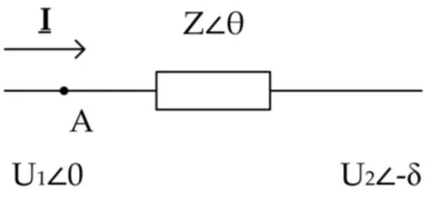
The transition from island operation back to grid connected mode should also be smooth and transient free so that loads do not experience disturbances during the transition, and for this a robust grid synchronization scheme is needed [33]. Gen-erally, before closing a circuit breaker with both sides of the connection energized, synchrocheck relays are used to ensure sucient synchronism between the two sides. This means the voltage magnitude, voltage phase angle and frequency dierences between both sides must be under set values and both voltage magnitudes over set minimums. [30] Ensuring small enough rate of change of frequencies and voltages is also commonplace. Traditionally, voltage regulation of passively managed distribu-tion networks is based on transformer on-load-tap-changers of HV/MV substadistribu-tions and o-load tap changers of MV/LV substations. However, the resynchronization of a microgrid requires ability to control the voltage in the islanded microgrid, and diers in many aspects from traditional synchronization of separate HV power sys-tems with large directly connected synchronous generators. To examine dierences in the underlying control mechanisms, consider a power line in Figure 2.5.
Figure 2.5 Model of a short power line.
The power ow at point A is
S =U1I∗ =U1(U1 −U2 Z ) ∗ =U1( U1−U2 δ Z −θ ) = U2 1 Z θ− U1U2 Z θ+δ (2.2)
whereU1 is the voltage at the beginning of the line, U2 the voltage at the end of the
line,δthe load angle andZ θthe line impedance. Rewriting 2.2 withZ θ=R+jX
2.2. Microgrid islanding and resynchronization principles 26 S = U1 R2+X2[R·(U1 −U2cosδ) +X·U2sinδ] +j U1 R2+X2[−R·U2sinδ+X·(U1−U2cosδ)] (2.3)
where R is the line resistance and X is the line reactance. Since S = P +jQ,
seperating to real and imaginary parts we get the active and reactive power:
P = U1
R2+X2[R·(U1−U2cosδ) +X·U2· sinδ] (2.4)
Q= U1
R2+X2[−R·U2· sinδ+X·(U1−U2· cosδ)]. (2.5)
For typical HV overhead lines, X >> R. By neglecting resistanceR and assuming
the load angle δ to be small, it can be approximated that sinδ ≈ δ and cosδ ≈ 1
and equations 2.4 and 2.5 can be reduced to
P ≈ U1U2 X δ (2.6) Q≈ U 2 1 X − U1U2 X (2.7)
From equations 2.6 and 2.7 it can be seen that with HV lines the active power
P and the load angle δ and thus the frequency f are related, while the reactive
power Q and the voltage dierence U1 −U2 are related. By adjusting P and Q
independently the frequency and voltage of the network can be controlled. This is the basis of so called conventional droop control, where linear approximations for the P/f and Q/U dependencies are used to control the active and reactive power outputs of the generators in the grid:
f −f0 =−kp(P −P0) (2.8)
U1−U0 =−kq(Q−Q0) (2.9)
setpoints for active and reactive power and kp and kq are the droop coecients of
active and reactive power [34]. Typical LV overhead lines, on the other hand, are dominantly resistive so thatR >> X. In this case, neglecting the reactance X and
with the same assumption of the load angle being small, we get
P ≈ U 2 1 R − U1U2 R (2.10) Q≈ −U1U2 R δ (2.11)
So in the case of a LV network, the dependencies are inverted: load angle δ and
frequency f are associated with reactive power Q, while active power P depends
mainly on the voltage dierence U1 −U2. This would suggest the use of so called
opposite droops, i.e. P/U- and Q/f-droops in voltage and frequency control. While P/U droop control would oer direct voltage control, Engler states in [35] that using opposite droops wouldn't make active power dispatch possible, and would lead to compatibility problems with directly connected generators and higher voltage levels. On the other hand, conventional droops are operable in the LV network DER inverters through the indirect operation of droops. The inverter power is adjusted by changing the inverter voltage with the reactive power Q, and because Q is a
function of the angle δ and δ is the integral over time of the generator's frequency
dierence with the grid, a P/f- and Q/U-droop control can be established at the cost of needing extra reactive power [35]. However, it is questionable if adequate reactive power resources are available at LV level, and decentralized conventional droop control without communication has its own technical challenges as well, as discussed in 2.1.1.
An island operated microgrid may be in synchronism with the utility grid right af-ter islanding, but as load and production changes in both the microgrid and utility grid, the phase angle dierence across the interconnection switch at the PCC will change, and needs to be minimized before reconnection [5]. The standard IEEE 1547 "Standard for Interconnecting Distributed Resources with Electric Power Systems" requires that the phase dierence across the interconnection switch must be less than 20◦ before the switch can close. However, Eto et al. conclude in tests conducted
at the CERTS Microgrid Test Bed near Columbus, Ohio, that even stricter require-ments are needed, suggesting closing "at a zero-phase dierence". [36] Laaksonen and Kauhaniemi state in [37] that with only converter connected DG units phase
2.2. Microgrid islanding and resynchronization principles 28
angle dierences as large as slightly over 60◦ can be acceptable depending on the
im-plementation of the DG control system. This is due to the phase locked loop (PLL) component of the DG unit converter drawing the converter to phase with the utility grid frequency after reconnection [38]. However, in the case of directly connected synchronous generators even a phase dierence of 22◦ resulted in large oscillations
after reconnection, and a phase dierence less than 10◦ was recommended. Closing
at a larger phase dierence can also strain the turbines and gearboxes potentially present in i.e. hydro and wind power plants.
As stated most of the DER units will be connected to the microgrid via power electronic interfaces and the resynchronization can potentially be done through the control of these units. The strategy used will depend on the chosen control concept of the microgrid: centralized control with one master unit or decentralized control of DER units through droop control. In a master unit conguration, one inverter such as a central energy storage is chosen as a master unit giving voltage reference to other active and reactive power (PQ) controlled DER units. In this case a resyn-chronization method such as proposed by Arulampalam et al. in [39] could be used where the PLL output angle θ is used in the energy storage controller to regulate
the set reference system frequency and thus over time minimize the phase dierence to acceptable limits. With P/f-droop controlled DER units all DER unit converters must be coordinated by a supervisory controller, using a method like shifting droop control presented by Qiang et al. in [40]. In order to vary the island frequency and thus the phase dierence, preset droop curves are shifted to change the operating frequency and voltage without changing the active or reactive power sharing between sources. The change in actual frequency is determined by the shifting oset value provided by the central controller, and thus communication is required for the resyn-chronization. The Q/f-dependency of LV networks discussed earlier can also provide an alternative way to control the phase dierence during resynchronization by coor-dinated reactive power set point changes of the DER units [38]. In [38] Laaksonen and Kauhaniemi also raise the possible issue of voltage unbalance in the microgrid due to load asymmetry and single-phase DER units, leading to phase dierence deviation between each individual phase during resynchronization. In their simula-tions controllable 1-phase loads were used to reduce the asymmetry, and potential practical implementations of 1-phase DG units, energy storages or controllable loads coordinated by the microgrid management system were suggested.
3. MICROGRID PROTECTION
In general, power system protection is responsible for detecting and isolating oc-curring faults or abnormal conditions in the network, protecting humans, animals and electrical equipment from potential damage. The power system is divided into protection zones, containing devices, typically circuit breakers, capable of isolating that particular part from the rest of the grid. These devices are controlled by the protection system consisting of protection relays, instrument transformers, and all the associated wiring, communication and automation. Main requirements for the protection system can be categorized as selectivity, speed and reliability.
Selectivity means that 1) only the faulty part of the network shall be isolated, thus minimizing the harm caused by the fault, and 2) every part of the network is pro-tected by at least one protection device. [30] Selectivity can be based on time delays coordinated between protection relays, or be implemented by dening appropriate operation curves for protection devices and their functions. Operation curves dene the time delay between relay pick-up and sending of the trip command as a func-tion of the measured quantity, enabling both selectivity in faults far away and fast fault clearance in nearby faults. For example an inverse-time over-current relay trips faster with higher fault currents. Figure 3.1 presents dierent operation curves for such a relay as dened in the standard IEC 60255, with IS being the chosen pickup
current. Operation speed of the protection system is very important in minimizing the negative eects caused by a fault.
Lastly, reliability of the protection system consists of two requirements. Security of protection ensures a relay does not send a tripping signal if there is no fault in its protection zone, i.e. there is no false operation. Dependability of protection means that the protection relay shall detect all the faults in its protection zone, i.e. the protection system must operate in all abnormal conditions. [30] A common practice is to also ensure redundancy of protection functions, so that a fault is isolated even if the associated main protection device fails to operate, conforming to the N-1
3. Microgrid protection 30
Figure 3.1 IEC overcurrent relay operation curves according to IEC 60255 [41].
criterion [30, 41, 42].
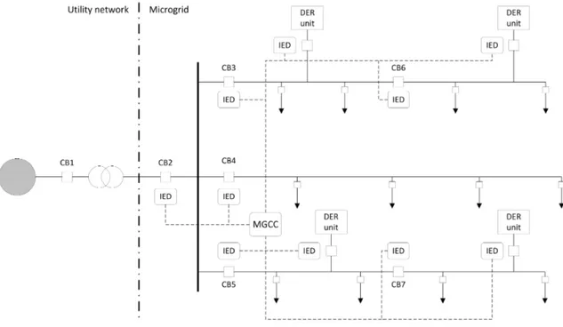
An example of a microgrid protection system based on [25] is shown in Figure 3.2. The microgrid central controller (MGCC) as a central entity is responsible for coordinating protection settings and communication based protection schemes between IEDs. It can also provide set points for voltage, frequency and active and reactive power outputs of DER units in the microgrid. In the case of a LV microgrid, it is questionable whether sectionalizing individual LV feeders to more than one protection zone, such as in the gure with CB6 and CB7, is justiable with the amount of faults in the LV network and associated outage costs [37]. Otherwise the example system gives an overview of typically available control equipment and entities regarding microgrid protection.
Figure 3.2 An example of a microgrid protection system.
The protection of microgrids has to solve two major issues in its design. Firstly, the conditions and operation times for islanding during possible faults in grid-connected mode must be examined. From operation point of view, maintaining the connec-tion between the microgrid and the utility is highly desirable, but when islanding is mandatory, the operation speed must be sucient to maintain stability of the microgrid after islanding as discussed in Section 2.2.2. Secondly, the stand-alone microgrid itself must be divided to protection zones with coordinated fault protec-tion that ensures sucient selectivity and prevents unwanted operaprotec-tions, such as unnecessary disconnections of DER units. [25]
The denition of "sucient selectivity" varies largely according to the size and volt-age level of a microgrid as well as chosen protection principles. It can be argued that a fault inside a microgrid after separation from the utility grid is an N-2 contingency, and the island can therefore be shut down without selectivity. If the microgrid con-tains enough critical loads or covers a large area, the added cost of coordinating protection zones inside the microgrid can be justiable. In this chapter protection schemes are reviewed regarding their technical capabilities and ability to support selective operation also in internal faults of the microgrid after islanding. First, the main protection issues regarding microgrids are presented. Next, possible non-adaptive protection schemes are examined, and then special attention is paid to the
3.1. Protection issues of microgrids 32
principles of adaptive protection, which has been widely presented as an important or even a necessarily required part of microgrid and active distribution grid protec-tion [4247]. Lastly one complete protecprotec-tion soluprotec-tion for a LV microgrid is presented as an example of possible merging of dierent protection methods.
3.1 Protection issues of microgrids
Due to the dierences discussed in chapter 2 between microgrids and conventional utility distribution networks in topologie
![Figure 1.1 SGAM Framework [8]](https://thumb-ap.123doks.com/thumbv2/123dok/1486429.2541951/14.892.184.757.390.835/figure-sgam-framework.webp)

![Figure 2.2 Typical microgrid management system [13].](https://thumb-ap.123doks.com/thumbv2/123dok/1486429.2541951/22.892.172.805.109.589/figure-typical-microgrid-management-system.webp)
![Figure 3.1 IEC overcurrent relay operation curves according to IEC 60255 [41].](https://thumb-ap.123doks.com/thumbv2/123dok/1486429.2541951/39.892.316.643.111.661/figure-iec-overcurrent-relay-operation-curves-according-iec.webp)
![Figure 3.3 Distance protection zones [65].](https://thumb-ap.123doks.com/thumbv2/123dok/1486429.2541951/50.892.202.772.397.613/figure-distance-protection-zones.webp)