A MULTI-RANGE APPROACH FOR CULTURAL HERITAGE SURVEY:
A CASE STUDY IN MANTUA UNESCO SITE
Silvia Chiarini a, Stefano Cremonesi a, Luigi Fregonesea,Francesco Fassib, Laura Taffurelli a
aDepartment of Architecture, Built environment and Construction engineering - ABC,
Politecnico di Milano, Campus Mantua, via Scarsellini,2 - 23100 Mantua (Italy) bDepartment of Architecture, Built environment and Construction engineering - ABC,
Politecnico di Milano, via Ponzio, 31 - 23100 Milan (Italy)
(silvia chiarini, stefano.cremonesi, luigi.fregonese, francesco.fassi, laura.taffurelli,)@polimi.it
Commission V, WG VI/4
KEY WORDS: Close range and aerial photogrammetry, Laser Scanning, UAV, Cultural Heritage
ABSTRACT:
In this paper, a Cultural Heritage survey, performed by employing and integrating different type of acquisition technologies (image-based and active sensor (image-based) is presented. The aim of the survey is to create a 3D multiscale database, therefore, different restitution scales, from the architectural-urban one to a detail one are taken in consideration. This research is part of a project financed by the Unesco for the study of historical gardens located in Mantua and Sabbioneta, and in particular for the Palazzo Te renaissance gardens in Mantua, which are reported in this paper. First of all, a general survey of the area has been realized by employing the classical aerial photogrammetry in order to provide the actual arboreal and urban furniture conditions of the gardens (1:500 scale). Next, a detailed photogrammetric survey of the Esedra courtyard in Palazzo Te has been performed by using a UAV system. At the end, laser scanning and traditional topography have been used for the terrestrial detailed acquisition of gardens and architectural façades (1:50-1:20 scale). The aim of this research is to create a suitable graphical documentation support for the study of the structure of the gardens, to analyze how they have been modified over the years and as an effective support for eventual future re-design. Moreover, the research has involved a certain number of botanic and archeological investigations, which have been duly acquired and modeled with image based systems.
Starting from the acquired datasets with their acquisition scales, a series of comparative analysis have been performed, especially for those areas in which all the systems have been employed. The comparisons have been extracted by analyzing point cloud models obtained by using a topographical network.
As a result, the multi-range approach efficiency, obtained by employing the actual available technologies have been illustrated in the present work.
1. INTRODUCTION
In Cultural heritage field for several years the survey knowledge and specialist skills has been very important not only for conservation projects but even for other type of studies and analysis. This is made possible thanks to the realization of 3D databases containing spatial and metric information from which can be extracted simply understandable technical representations and virtual data easy to be managed even by other fields scholars (Manfredini-Remondino 2012, Fassi et al. 2011, Remondino et al. 2009, Fregonese, Taffurelli 2009). This permit to use the amount, quality and accuracy information that can be achieved through the integration between topographic and photogrammetric data acquisition systems, in a wide range of study-fields.
This research is part of a project funded by the Unesco for reach a systematic and in-depth knowledge of the sites place under guardianship included in the World Heritage List. The research is focused on the Renaissance (urban and suburban) gardens
located in Mantua and Sabbioneta, inside Gonzaga’s palazzo Te
and Palazzo Giardino until today still poorly known and studied. Therefore an accurate survey and critical analysis were required.
The overall aim regarded the conservation and requalification project supported by a depth historical- archival study and a 3D
survey managed in different restitution scales, from the architectural-urban one to a detail one.
In this context it was also carried out an archeological-botanical survey for the study of hydraulic management system and
existing plan species in the Gonzaga’s gardens. Moreover an upgrade of the present cartography, with the correct individuation and positions of the vegetation elements was required, to obtain a revised catalog of the greenery currently present in the place.
This paper presents the indoor and outdoor gardens in Palazzo Te surveys, performed by employing and integrating different type of acquisition technologies: image-based, active sensor based and UAV system.
1.1 The place
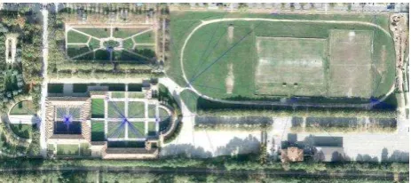
Palazzo Te is a renaissance palace (1535), originally located on an island, covered by designed gardens and crossed by avenues. The palace has a square plant, with a central courtyard of honour and a private garden on the East side, enclosed by architectural scenes (the most important is the Esedra), and other buildings, likes the secret apartment and the fruttiere. The area surrounding the building nowadays results under the level of the city ground and still show the perimeter of the old
island. Currently it is covered by some earlier designed gardens, avenues, parking, unused meadows and some football field.
1.2 The goal
The goal of the job was to test different applications of aerial (UAV and classical by plane) and terrestrial photogrammetry surveys for various representation scale, combined with TLS survey as control and integration, to represent as completely as possible the entire area and the internal gardens and frontages of the palace. Besides the production of useful representations for the studies, the purpose was also a didactic one. As a matter of fact, this project has been an occasion for a group of architectural students to apply some of most recent surveys techniques, on one of the most important buildings in Mantua.
1.3 The methodologies : the survey techniques
For a general survey of the area the classical aerial photogrammetry has been employed in order to provide the actual arboreal and urban furniture conditions of the gardens. TLS and terrestrial photogrammetry, with a traditional topographic survey, has been chosen to perform and control the architectural scale one. A UAV photogrammetry acquisition has been perform as a test and to eventually complete the aerial surveys with a higher resolution image.
1.4 The methodologies : the elaboration methods
To obtain accurate image based models, with short time of acquisition and elaborations, are now available a certain variety of new photogrammetric software, which allows to process data in an autonomous way, reconstructing tree-dimensional object from images acquired even using non metric cameras. These softwares automatically detect tie points for exterior orientation parameters computing, giving back a dense image-matching point cloud and even textured surface mesh models.
The photogrammetric software chosen for the realization of the
internal gardens and palace’s internal frontage models is Agisoft by Photoscan. As known it is a completely autonomous software able to orient and match densely a high number of good structured acquired images. (Fassi et al. 2013, Remondino et al. 2012) This software has been commonly employed in survey practice by these team, giving accurate results in complex architectural object’s applications, with short time of elaborations.
In order to help the image orientation process for the creation of the model, to scale and insert all the photogrammetric models and the surveys obtained with other technologies (TLS) in a unique coordinate system, a topographic placement network has been realized on place with a total station Leica TS30. At this purpose it has been placed properly both photogrammetric targets and TLS ones.
For the orientation of the internal garden model, some UNI A2 format targets has been placed on the ground considering the UAV acquisition distance of about 50 meters highness, while regular ones has been used for the internal frontage acquisition.
2. THE MULTISCALE SURVEY
2.1 Aerial Photogrammetry
For the first step, as a survey at a urban scale of the entire area
670meters to obtain a GSD of 4cm. The acquisition has been performed with a Vexcel UltraCam Xp with a 67.860x103.860mm sensor (11310x17310pix), a pixel size of 0.006mm and a 100.500 mm focal length. The acquisition consist in a 14 images horizontal strip covering an 440000 meters area.
The digital orthophoto provided had no georeferencing data, therefore some references have been exctracted from the laser scanning survey and known topographic points and have been used for the correct positioning of the orthophoto.
The ortho also had some problems related to the correct
location of the Palazzo Te’s roofing, in particular in the exedra
garden area.
Moreover, infrared images has been acquired to individuated garden foundation structures, which are possibly under the ground. This is a useful application for other archeological research.
The aerial ortophoto provided has been used for the re-drawing of the entire area, however for a correct and more detailed individuation of the mains buildings perimeter, the components
hidden by trees’ crowns and to achieve a higher precision on ground altitude measurements, a TLS survey has been performed as an integration and for the terrestrial acquisition of the vegetation elements. Moreover, for a comparison with the further surveys performed with other methods, and to obtain a
better positioning of the Palace’s roofing, the single aerial images has been re-oriented with Photoscan.
The new model has been obtained by the orientation of 6 cameras, with 631861 points sparse cloud and a 85501438 dense cloud. The photogrammetric cloud has been orientated with 7 control points. The coordinates has been extracted from the TLS cloud because, back when the aerial flight was
performed, the topographic network haven’t been placed yet.
The error obtained on the control point is 0.0173pix and 0.046 meters.
Figure 1. Aerial ortophoto with the 13 topographic stations from which were acquired laser scanning and photogrammetry
targets
2.2 UAV survey
UAV (Unmanned Aerial Vehicle) surveys in the last years become a quite employed method in architectural and archaeological field (Fiorillo et al. 2013; Rinaudo and Lingua, 2012; Remondino et al. 2012; Remondino et al. 2011; Campana et al. 2010).
In Palazzo Te, the Esedra courtyard survey has been integrated with UAV photographic acquisitions, which involved data capture quite close to the ground (about 55 meters) and a large amount of images to cover entire area. This choice allowed to test UAV applications on the field obtaining as a result an
closest acquisition permitted to acquire pitched roof in higher accuracy and the garden area hidden by building parts, in order to create representation to 1:50 scale.
In regard of the licensing requirements for UAV flight in Italy, when the Esedra courtyard survey has been performed the Italian Civil Aviation Authority (ENAC) regulations were not yet adopted as law. The flight in VLOS modality (Visual Line Of Sight) has been made by a specialized company and only above Palazzo Te property in closing time, therefore there
weren’t people extraneous to the survey during UAV flight in the area. It has been contacted the Palazzo Te administration for the authorization.
From April 30th 2014, the ENAC regulation was entered into force. Nowadays it regulate the using of unmanned aerial vehicle employed in specialized and experimental operations, in addition to the model aircraft used for recreation and sports events.
The regulation’s provisions depends on the maximum take-off mass of the UAV. The unmanned aircraft with a maximum take-off mass less than 25 kg are treated differently from those with a maximum take-off equal to or more than 25 kg.
In order to execute specialized operations, UAV operator must obtain an ENAC authorisation, providing evidence that it complies with the necessary requirements.
The remote pilot, designed by the operator like the person responsible for the flight, must have several qualifications in order to drive UAV systems.
Another important requirement is to stipulate a third party insurance.
The specific provisions about remotely piloted aerial vehicle can be found in ENAC website (www.enac.gov.it).
The used UAV was an Aeromax Camera System assembled by Microgeo. The used system was quite a little quadcopter able to carry on a Canon PowerShot S100. The compact camera have a pixel size of about 2 microns on a 7.6 x 5.7 mm CMOS sensor. not professional pilots, and it is completely automatic.
The plan was designed considering both survey requirements but also UAV autonomy and, hence, the fly time. The fly height was planned at 55m ensuring a ground pixel size of 2 cm. Six strips with a long track overlap of 70% and a cross-overlap of approximately 50%. No cross strip were done for the explained time limit limitation.
The position of the camera is quite accurate on the X, Y position and on the elevation point of view. The orientation of the camera is not very nadiral to the ground due the inclination of the drone in the flight direction and the lack of a proper camera stabilization device.
17 GCP was disposed of the ground to cover the entire area and a total station measurement was performed in order to georeference the UAV survey in the local georeference system and to test the accuracy of the photogrammetric process. The orientation was done using, once again, Agisoft Photoscan.
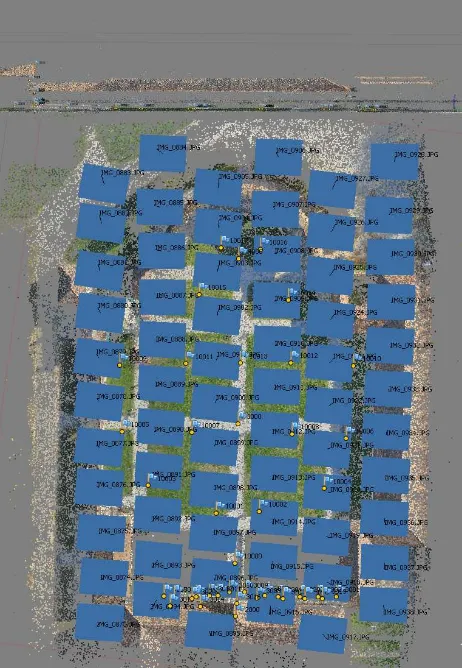
Figure 2. Flight structure. 66 images taken at 55m height.
The use of GCP is required in order to perform the optimization of the orientation that mean the correct interior orientation parameters that are not involved in the initial calculation by the Photoscan software. As it is possible to see in the Table 1 and on Figure 2 (the blue stack), the errors on the GCP after the first raw orientation is approximately of -2 cm for the external points and circa +2cm for the central points. That means that the orientations is wrong and the resulting point model have a concave deformation due to false interior orientation parameters. The red stack on the figure show the situation after the correct optimization where the errors are about 5 mm
Table 1. Synthesis of the orientation residual before and after optimization
Figure 3. Orientation residual distribution, blue ones before optimization, red ones after optimization.
2.3 Terrestrial Photogrammetry
For the terrestrial photogrammetric acquisition of the internal façades, the palace had been split into several lots. The Courtyard of Honor has been acquired as a unique lot, thanks to the similar form and dimensions of the frontages and the possibility of free movement into it, while the internal garden must be split into 8 lots. This is due to the different form and dimension of the single façades and to the presence of fishponds, hedges and structures in the garden which prevent neither to keep the same acquisition distance, nor to use the same focal length for all the acquisitions. Two additional lots in the internal garden were constituted by the archaeological remains of two corner fountains, where a detailed acquisition were required by the customers for archaeological researches. The camera used for the acquisitions is a Canon EOS 5D Mark2, with a sensor dimension of 5760x3840 pixels and a square pixel size of 0.00643599mm. Three different lenses has been used: 24mm, 35mm and 85mm.
For the orientation and realization of the photogrammetric models, the topographic placement network has been realized, fixing up four topographical station for the acquisition of 114 control points (42 for the Honour Courtyard and 72 for the internal garden).
The Courtyard of honour has been acquired with a 85mm lens with a 12.5 meters acquisition distance from the object. The lens was chosen, considering the distance, to cover a large part of the façade making possible the reconstruction of more architectural edges. The photogrammetric model has been
The East façade, in the esedra courtyard, has been acquired with a 85 mm lens, which has been chosen because the presence of the Fisheries imposed an acquisition distance of 25 meters. The photogrammetric model has been constructed with 91 images using 19 control points with a medium error of 0.009851 m and 0.236 pix. The orthophotos of the façade has been made with a pixel dimension on the object of 2 mm.
In tab 1 the data related to each lot’s photogrammetric model
are reported, specifically: the dimensions (weight, height) referred to the surface of the frontage contained into the lot, in the cases of the 2 corner fountains it’s reported the ground archeological area around the frontages; the focal lens used for the acquisition (chose in relation to the dimension and the distance of acquisition); the acquisition distance (distance between the object and the camera); the number of images used to construct the model; the number of matching points recognized by the software; the number of points used for the orientation of the models; its errors expressed in meters and pixels and the Ground Sample Distance.
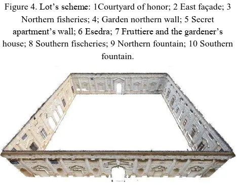
Figure 4. Lot’s scheme: 1Courtyard of honor; 2 East façade; 3 Northern fisheries; 4; Garden northern wall; 5 Secret
apartment’s wall; 6 Esedra; 7 Fruttiere and the gardener’s
house; 8 Southern fischeries; 9 Northern fountain; 10 Southern fountain.
Figure 5. Lot: Courtyard of Honour. Photogrammetric dense cloud.
From the image-based models obtained has been extracted the 1:50 scaled ortophotos created with a 2 mm pixel dimension (chosen considering the final scale of the supports) which has been used for the geometrical drawings of the architectural frontage of the palace.
The ortophoto obtained resulted an optimal support for the
Lot Frontage dimension (m) Lens (mm) Acquisition distance (m) N° images
Table 2. Photogrammetry 3D model data.
Figure 6. Courtyard of Honour internal north frontage orthophoto from Photoscan.
2.4 Laser scanning
TLS database have been adopted like Photogrammetry
elaborations’ control and integration. The internal façade
orthophotos have been checked and the absence of knowledge caused from blooming vegetation in the external gardens have been completed by laser scanning data. Specifically, the inside courtyard frontages have been represented on the base of
Photoscan’s elaborations and TLS data have been used to prove relative accuracy. Indeed internal laser scanning frontages, have been elaborated with Pointools to create orthogonal views used for comparison with façade orthophotos. The Pointools elaboration were created on the base of single scanning, not by oriented one; in this way the accuracy achieved is that of laser scanning technology. On the outside frontages representation
weren’t requested, but the greenery condition prevented the
clear area survey from aerial photogrammetry, therefore the zone covered by trees have been acquired with TLS technology. In this way, elements like pedestrian path, urban furniture, trunk location and ground altitude have been distinctly surveyed to complete the area drawing.
In this work laser scanning acquisitions have been made with
HDS7000 scanner by Leica Geosystems, it’s a phase shift tool
with onboard control system which can acquire more than 1 million points/second. Its acquisition range moves between 0,3 and 187 meters and it works with 360°x320° field of view. Palazzo Te gardens acquisitions have been made in super high resolution, permitting to obtain a points spacing equal to 3,1 mm at 10 meters away. Laser database has been composed of 33 scans (7 internal, 26 external) for a total amount of 3.185.540.256 points (1.589.894.964 internal, 1.595.645.292 external) and they have been oriented with a topographic placement network arranged by 13 topographical stations from which were acquired 66 GCP. The overall average error obtained for scans orientation was about 0,01 m.
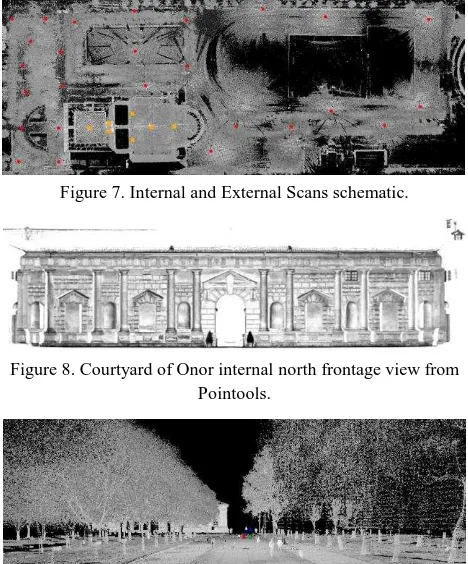
Figure 7. Internal and External Scans schematic.
Figure 8. Courtyard of Onor internal north frontage view from Pointools.
Figure 9. Palazzo Te external scan view from Cyclone.
3. DATASET COMPARISON the dense cloud points obtained by UAV flight.
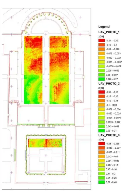
Figures 11 and 12 represent the same areas where the GRID were obtained respectively from the dense clouds of the flight data and photogrammetric scans TLS.
Starting from these homogeneous data the surface differences obtained have been determined. The first differential surface was obtained by subtracting the UAV GRID data to aerial photogrammetry ones (figure 13).
Figure 14 illustrates the difference obtained by subtracting from UAV GRID data, the TLS ones. Figure 15 illustrates the variation between aerial photogrammetry GRID and TLS ones. For further analysis, a comparison between individual datasets with GCP into test areas previously showed, was carried out. In the following table 3, starting from GCP altitude data, were defined the errors of individual datasets expressed in meters (presented in columns). In the last line, the obtained standard deviation values are exposed.
Figure 10. GRID – UAV, study areas. Figure 12. GRID – TLS, study areas.
Figure 14. Delta UAV-TLS, study areas.
Figure 15. Delta Aerial Photogrammetry -TLS, study areas.
ID GCP Z (m) GCP-UAV
Z (m) GCP-PHOTO
Z (m) GCP-TLS
10001 0,003 -0,035 -0,017
10002 0,001 0,051 -0,024
10007 0,006 0,093 -0,033
10008 0,003 0,064 -0,026
10011 -0,006 -0,070 -0,054
10012 0,003 -0,130 -0,045
10014 0,003 -0,070 -0,074
10015 0,010 -0,150 -0,079
z (m)
±0.005 ±0.091 ±0.023Table 3. Synthesis of the residual and standard deviaton between GRID surface e GCP
From the data is evident that:
there is a good correspondence between the GCP and the datum UAV. This is inevitable, as they are the same points used for the orientation of the frame; The standar deviation in the case of TLS datum is
consdered as acceptable in regard to the reference comparison surface (turf);
The standard deviation is eccessive in the case of the aerial photogrammetry flight. In this case, it is an expected result as dependent on the method of orientation of aerial images previously described.
4. THE FINAL DRAWINGS AND
REPRESENTATIONS
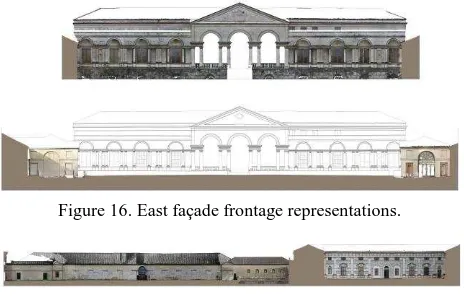
As a result of the entire survey a series of drawings has been produced such as: The complete 1:500 planimetry of the entire area surrounding the palace, considering trees, boulevards, lanes, urban fabric and other buildings. The planimetry contains
the aerial ortophoto and it’s completed by a network of height
measurements (with a 20 meters step) for the understanding of
the ground’s elevation profile; The 1:50 scale planimetry of the
internal gardens and courtyard, included in a 2 meters height section of the internal frontages of the building. The planimetry has been completed with the detailed ortophotos (produced for a more detailed scale) of the archeological remains of the two corner fountains; The 1:50 scale drawings of the frontages with the related ortophotos inserted in 7 significative sections of the building.
Figure 9. Planimetry of the area.
Figure 16. East façade frontage representations.
Figure 17. East façade frontage representations.
5. CONCLUSION
In this paper various survey technologies (aerial photogrammetry, UAV, TLS and topographic) has been integrated to obtain a complete 3d database of a palace and the urban area surrounding it.
The comparison between the data collected and consequently elaborated, demonstrate how different technologies are not easily comparable due to a different response of the surfaces analysed. On the other hand this experience gave the possibility to test some of the most potentially valid survey techniques for different representation scale and type of subject (a urban area ground, gardens, architectural façades), demonstrating the applicability and the efficiency of this techniques. This was also a great testing ground for didactic experiences, introducing future architects in the field of photogrammetry and TLS survey, giving them the possibility to apply concretely on one of the most important building in Mantua, some of the most advanced survey methods.
It was even possible to join all the data and elaborations collected into a unique 3D database from which can provide the data necessary to obtain all the drawings and information required by the costumers for further analysis.
6. ACKNOWLEDGEMENTS
The authors would like to thanks Dott. Stefano Benetti, Mantua Civic Museum Director; Microgeo s.r.l.; dott.ssa Susanna Sassi, Mantua Unesco Office; Blom CRG s.p.a. and dott. Tommaso Chiarini, Tea Ambiente s.p.a.
7. REFERENCES
Fassi, F., Fregonese, L., Ackermann, S., De Troia, V., 2013. Comparison between laser scanning and automated 3D modelling techniques to reconstruct complex and extensive cultural heritage areas. In: Proceeding of: International Archives of the Photogrammetry, Remote Sensing and Spatial Information Sciences-3D-ARCH - 3D Virtual Reconstruction and Visualization of Complex Architectures, Volume XL-5/W1;
Fiorillo F., Jiménez Fernàndez-Palacios B., Remondino F., Barba S., 2013. 3D Surveying and modelling of the
Manfredini A.M., Remondino F., 2012. A Review of Reality-Based 3D Model Generation, Segmentation and Web-Reality-Based Visualization Methods. International Journal Heritage in the Digital Era, 1(1), pp. 103-123.
Remondino F., Del Pizzo S., Kersten T.P., Troisi S., 2012. Low-Cost and Open-Source Solutions for Automated Image Orientation – A Critical Overview. In: Lecture Progress in Cultural Heritage Preservation. Notes in Computer Science. Proceedings of EuroMed 2012, Limassol, Cyprus, October 29 – November 3; Ioannides M., et al., Eds.; Spinger-Verlag: Berlin Heildelberg, Vol. 7616, pp. 40-54.
Rinaudo F., Chiabrando F., Lingua A., Spanò A., 2012. Archaeological site monitoring: UAV photogrammetry can be an answer. In: proceeding of: International Archives of the Photogrammetry, Remote Sensing and Spatial Information Science, Melbourne, Australia; Vol. 39-B5, pp. 383-388;
Fassi F., Achille C., Fregonese L., 2011. Surveying and modeling the main spire of Milan Cathedral using multiple data sources. Photogrammetric Record, 26, pp. 462-487.
Remondino F., Barazzetti L., Nex F., Scaioni M., Sarazzi D., 2012. UAV photogrammetry for mapping and 3D modelling – current status and future perspectives. In: proceeding of: International Archives of the Photogrammetry, Remote Sensing and Spatial Information Sciences, Zurich, Switzerland, 14-16 September 2011; Volume XXXVIII-1/C22;
Remondino F., Nex F., Sarazzi D., 2011. Piattaforme UAV per applicazioni geomatiche. GEOmedia, 6, pp. 28-32;
Campana S., Sordini M., Rizzi A., Remondino F., 2010. Geomatics techniques for the 3D documentation and visualization of archaeological building. In: Space, Time, Place. Proceedings of Third International Conference on Remote Sensing in Archaeology, Tiruchirappalli, Tamil Nadu, India, August 17-21, 2009; Forte M., Campana S., Liuzza C. Eds.; Archaeopress Ltd: Oxford, England; pp. 151-154.
Remondino F., Girardi S., Rizzi A., Gonzo L., 2009. 3D Modeling of Complex and Detailed Cultural Heritage Using Multi-Resolution Data. ACM Journal on Computing and Cultural Heritage, 2(1), pp. 2.
Fregonese L., Taffurelli L., 2009. 3D model for the documentation of cultural heritage: the wooden domes of St.
Mark’s Basilica in Venice. In: Proceeding of: International Archives of the Photogrammetry, Remote Sensing and Spatial Information Sciences-3D-ARCH- 3D Virtual Reconstruction and Visualization of Complex Architectures, Volume XXXVIII-5/W1.