SIMPLE ROOM SHAPE MODELING WITH SPARSE 3D POINT INFORMATION
USING PHOTOGRAMMETRY AND APPLICATION SOFTWARE
S. Hirose
R&D Center, TOPCON CORPORATION, 75-1, Hasunuma-cho, Itabashi-ku, Tokyo, Japan
Commission V, WG V/4
KEY WORDS: Photogrammetry, 3D shape modelling, Drawing sheets, Development figure, Coded-Target, Indoor modelling
ABSTRACT:
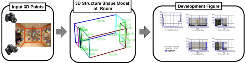
In this paper, we propose an automated technique for creating a simplified 3D structure shape model of indoor environments from the sparse 3D point information provided by the photogrammetric method. Multiple coded-targets are used for the automatic detection, recognition and measurement of 3D coordinates of points on the room walls from the acquired stereo images. The sparse 3D information is then processed by our software for the estimation of a simplified 3D structure shape model of the room. Additionally, the 3D model is also translated into a development figure which represents multiple orthographic projections of the room. The proposed method is implemented into a flawless procedure which allows to obtain, by a few operations, a simplified 3D structure shape model of a room and its orthographic representation in drawing sheets. The developed application software can be used for the determination of the shape of rooms easily also by persons without experience in 3D measurement techniques.
Figure 1. Overview of the proposed system. Left: color-coded targets are placed on the walls of a room, stereo images are processed photogrammetrically and sparse 3D points coordinates are obtained. Center: a simplified 3D structure shape model of the room is constructed from the sparse 3D information. Right: the development figure is generated by orthographic projection of the 3D model.
1. INTRODUCTION
The 3D reconstruction of indoor environments is important task for architecture field. Repair works in a building may be conducted for finishing the interior or for changing the layout of a room. The decision of starting repair works is based in mostly cases on their rough costs which are estimated from the size of the walls or from the room footprint. This information is usually obtained from the technical drawing sheets of the building. However, such important information often is not available in cases of buildings that have been built few decades ago. In other cases, the drawings do not represent the current state of the rooms because of previous repair or maintenance works. In these situations, in order to obtain the required shape and sizes of the considered rooms, measurements have to be made manually by tape measure or by laser distance meter. This procedure may be difficult and complex depending on the shape of the room. Moreover, measurements have sometimes to be repeated because of objects and elements of the room, as windows or doors, that were forgotten to be measured. In addition, the whole procedure of taking manual measurements requires a lot of time. It is thus strongly wished by many repair workers to streamline the measurement process of a room.
Recently, terrestrial 3D laser scanners have been employed for the measurement of interiors of buildings (Budroni 2010). A 3D laser scanner generates a dense 3D point cloud of a room in few minutes and it can be used for reconstructing its structure, including complex details as window frames. For this reason, laser scanners have been frequently used for precise and thorough measurements in large building, like airports or bridges. However, in spite of the precision and extension of the obtained 3D point cloud data, this only estimates the surface of the measured objects and it does not give a structural description of them. Moreover, it is difficult to measure the size of objects from 3D point cloud data without their edges, and the process of extracting edges of objects from the point cloud data is complex and computationally heavy. The cost of the equipment and the required technical skills to operate 3D laser scanners and process the resulting data are also negative issues for their use in our case of simple repair works. Additionally, the measurement accuracy of laser scanners is much higher than what is required for the rough cost estimation of repair works. For all these reasons, 3D laser scanners cannot be considered the adequate measurement systems for our case.
Figure 2. Overview of the processing steps. Top Left: color-coded targets are placed on the walls of a room and multiple stereo images are acquired. Top Center: 3D point coordinates are determined by photogrammetry. Top Right: by using normal vector information, the 3D points are clustered for each wall. Bottom Right: the wall sequence order is decided. Bottom Center: intersection
lines are estimated for each neighboring walls. Bottom Left: corner points are estimated and the 3D shape model is constructed.
We propose instead a method for the automatic modelling of simplified 3D structure shape of rooms by using sparse 3D point information. The main advantages of the proposed method are the simple required equipment and the simple acquisition and processing. Additionally, it is possible to add new measurements without the need of new acquisitions: in fact, the reconstructed simple 3D shape model of a room can be easily extended with new details like window frames or doors in post-processing works without the need to perform new measurements in the building. Moreover, the reconstructed 3D room shape model is translated into the development figure which represents orthographic projections of the room and which is very useful for repair works planning.
The simple 3D room shape model is reconstructed from 3D sparse points obtained by photogrammetry. The 3D data is processed automatically and in short time. Figure 1 shows the overview of the proposed method and Figure 2 describes the different processing steps to reconstruct the simple 3D room shape model.
The contributions of this paper are the following:
1. We formulate the automatic technique for the simple modelling of room structure shape by sparse 3D point information provided by the photogrammetric method.
2. We propose a method for translating the simple 3D room model into development figures.
The rest of this paper is organized as follows: after reviewing related works in Section 2, we describe our method for constructing the 3D room shape model in Section 3. In Section 4, we describe the process to obtain development figures. In Section 5, we show experimental results to verify the effectiveness of the proposed method. Section 6 concludes this paper.
2. RELATED WORKS
Various 3D reconstruction methods have been proposed for modelling buildings, landscape and objects. These methods can be classified into three classes: (1) model-based approaches, where scenes or objects are reconstructed from simple geometric primitives such as column, cylinder, cone, sphere (Khalil et al. 2001, 2002, Devevec 1996); (2) dense approach, where the objective is to capture fine details (Goesele 2007, Seitz 2008, Sinha 2008); (3) depth map integration approach (Furukawa 2009), which is similar to dense approaches (Zach 2007).
Khalil et al. have proposed the model-based approach for 3D indoor modelling of buildings. This method assumes that indoor objects as window frames, doors, rooms or corridors are modelled by simple primitives. This modelling method consists of three steps: geometric modelling, topologic modelling and semantic modelling. By the geometric modelling step, indoor geometric elements are extracted from images by the photogrammetric method. The extracted elements are modelled by means of their borders. The relationships between each modelled component (room, corridor, etc) are manually defined in the semantic modelling step with the help of a GUI software, where different types of surfaces are available, as wall, ceiling, ground, window, etc. The final 3D model is constructed by combining all the elements. The advantage of the model-based approach consists in the lot of semantic information included in the generated 3D model, compared to general 3D shape models. The drawback is however the required manual operations for the definition of types of surfaces.
The second class of modelling approach is based on the multi-view stereo (MVS) method where camera parameters are estimated and a dense 3D point cloud is obtained from images by using Structure-from-Motion (SfM) algorithms (Goesele 2007, Seitz 2008). These methods employs the SIFT operator
Figure 3. Color-coded target: the different color patterns of the coded target are used for the identification; a single coded
target features three circular signalized points. Right: the normal vector can be calculated by the measured three
signalized points.
(Lowe 1999) as feature points detector, which works well for extern building reconstruction. However, for indoor scenes, SIFT cannot perform robustly because of poor texture information on the room walls and therefore in this case feature points cannot be stably extracted.
Furukawa et al. have improved the dense approach for the reconstruction of indoor scenes (Furukawa 2009). Firstly, camera viewpoints and parameters are estimated by using Structure-from-Motion algorithms. A 3D dense point cloud is then estimated by Patch-based Multi View Stereo (PMVS) approach. In the next step, a depth map of the scene is constructed by the Manhattan World Stereo method which assumes that surfaces are piece-wise planar and aligned with three dominant directions. In the final step, the depth map is merged to generate surfaces from graph-cuts (Boykov 2001) by each planar area. This method produces sometimes errors because of feature point mismatches. In fact, natural features cannot guarantee robust results.
In our approach, precise and sparse 3D coordinate of points on walls are extracted by photogrammetry. Simplified 3D shape model of room is constructed by few operations and fast processes. Additionally, we translate the 3D shape model into drawing sheets.
3. 3D STRUCTURE SHAPE MODEL OF ROOM
In this section, we propose the estimation method of 3D structure shape model of room. First we estimate 3D coordinates of points on walls. Second we cluster these points by each wall. Next, we determine wall sequence order. Then, we add the height of wall and construct 3D structure shape model of room. We assume that the 3D room shape model is consisted of planes of walls in a horizontal direction, one flat ceiling and floor.
3.1 Extraction of 3D points by photogrammetry
Coded targets are placed on the walls of the room to be modelled. Multiple stereo images of the room are then processed by photogrammetry to determine the 3D information that will be used for the modelling process. The gained 3D data consist of 3D coordinates of the targets on the walls and their normal vectors. The information about the normal vector of a wall is important for estimating the structure shape of the room (as it will be explained later). For this reason, we employ color-coded targets that have been proposed in our previous work (Moriyama 2008).
The color-coded target features different color patterns that serve for the automatic recognition. Three signalized circular points are included in a single coded target. These are automatically measured in the images and can also be used to estimate the normal vector of the target surface (see Figure 3).
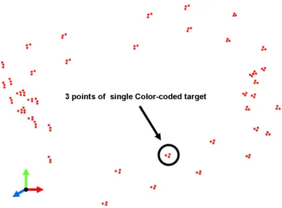
Figure 4. Extracted 3D coordinates of points.
Furthermore, the distance between the three circular points in the color-coded target has been previously defined, so that the real scale of a scene can be determined from distance between them in the images. The 3D coordinates of the three circular points in all the color-coded targets placed on the room walls are calculated by stereo photogrammetry (see Figure 4).
3.2 Estimation of room wall planes
The plane of a wall is defined by a normal vector and the 3D coordinates of a point on the wall. For a precise and robust estimation of the wall planes, we have clustered by each wall the 3D points extracted by photogrammetry. The clustering process consists of the following four steps:
Estimation of normal vectors for all color-coded targets (see Figure 5, top left), from the 3D coordinates of the even though Figure 5 features four different directions, this is not a given limit.
Refinement of the clustering. The average normal vector of roughly clustered points is used as axis for refining the clustering. The 3D points are clustered by the value of their projection onto that axis. In fact, 3D points on the same wall are projected to about the same position and points on different walls have different positions on that axis (see Figure 5, middle). The case of posts included on a wall is also considered: in fact, in such situation the projection onto the axis is equivalent also for points of different walls (see Figure 6). For this reason, normal vectors of the same cluster are analysed and if normal vectors of other clusters are found between them, then these normal vectors are divided into two different clusters.
Estimation of parameters and equations of wall planes, by the 3D coordinates of clustered points and normal vectors (see Figure 5, bottom left).
Figure 5. Clustering process. Top Left: the black dots represent the 3D points of color-coded targets, the black arrows represent their normal vectors. Top Right: rough clustering of 3D points
by directions of their normal vectors. Middle: refinement of clustering; the red axis is defined as clustering axis, and 3D points (green) are clustered by the value on the axis. Bottom Right: the result of clustering refinement on a direction. Bottom
Left: final result of the clustering process.
Figure 6. Clustering refinement method in detail. Left: the value of the three points (blue arrows) projected on the axis (red) is equivalent, these points are thus clustered as one wall. These points should however be clustered as two walls. Right: when points of different values on the axis (marked with the red circle) are found between clustered points, then these points
are clustered as two different walls (turquoise and blue arrows).
3.3 Determination of wall sequence order
The alignment sequence order for the walls is determined in order to estimate the intersections of neighbour walls. The procedure is described in the following steps. Firstly are estimated the center points (Pi) of the 3D points on each wall (i represents wall id number); then, the center of mass point (C) of all center points (Pi) is calculated. As second step, wall vectors (Vi) are defined from C to Pi (see Figure 7, left). A selected representative wall vector is then set as standard vector (S). This is rotated by arbitrary angles and the dot products of the rotated standard vector (Sk) with all wall
Figure 7. Determination of wall sequence order.
Figure 8. Determination of wall height. Points on the border lines between ceiling, floor and a wall are selected in the
orthographically projected image.
vectors (Vi) are calculated by each rotation. The wall vector which has maximum of dot product change is found for each rotation and this information is used in order to determine the correct alignment sequence order of the walls (see Figure 7, right).
3.4 Adding ceiling and floor information
The correct height of the room is required to construct its simplified 3D model. However, the heights and location of the ceiling and the floor of the room are unknown because the color-coded targets cannot be placed on their surfaces. In order to obtain the height of a wall, its orthographically projected image is generated and ceiling and floor border points are manually selected on the image (see Figure 8). The orthographically projected image includes 3D coordinate information for each pixel, so that the wall height can be directly obtained from the ceiling and floor points.
3.5 Construction of 3D room shape model
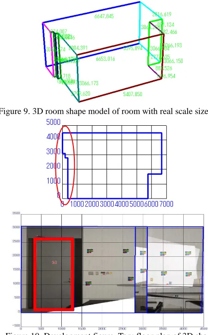
The corner points defining the structure and shape of the measured room are estimated from the intersections of ceiling and floor planes and neighbour wall planes. The simplified 3D shape model of the room is then constructed by joining the determined corner points with polylines (see Figure 9). The obtained 3D shape model features real scale size information (the 3D points have in fact been transformed into real scale coordinates using the information of the length between the
three circular points on the used color-coded targets) (see Figure 9).
In addition to the simplified 3D room shape model, our method allows to add in a very simple way details and objects like doors, windows, paintings, etc.(see Figure 10 Bottom: A door is modelled by red square.). These details can be manually modelled and inserted in the 3D shape model.
Firstly is generated an orthographically-projected image of the wall containing the object to be modelled. Then, points of the contour of the object are traced manually on this image. The resulting 3D data can be directly inserted into the 3D room shape model.
4. GENERATION OF DEVELOPMENT FIGURES
The reconstructed 3D room shape model is translated into development figures which represent orthographic projections of the room in different directions. These figures can be considered as drawing sheets and are very useful for repair works planning. The procedure to generate development figures is described as follows. All the walls in the simplified 3D shape model are clustered in four main groups by using the directions of the wall normal vectors. Orthographic images are then generated for each wall by projecting them onto a single plane at four directions. Figure 10 shows the floor plan of a 3D room shape model and the development figure for one direction which is composed of three different walls (red ellipse). Figure 11 shows the complete development figure including floor plan and four orthographic projections.
Figure 9. 3D room shape model of room with real scale size.
Figure 10. Development figure. Top: floor plan of 3D shape model. Bottom: development figure for one direction. Added
Door (red square).
Figure 11. Development figure.
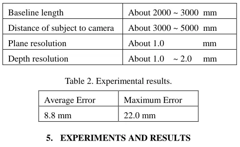
Table 1. The conditions of the experiment.
Baseline length About 2000 ~ 3000 mm
Distance of subject to camera About 3000 ~ 5000 mm
Plane resolution About 1.0 mm
We conducted an experiment involving five non-professional persons who are amateurs of stereo image capture or of photogrammetry. These persons have reconstructed 3D shape models of different rooms by our proposed method. The sizes of the rooms were between 30 m2 and 70 m2. Totally 14 room shape models were obtained, each person worked on 1~5 rooms. In this experiment, we used a DSLR camera Nikon D90, equipped with 28mm f2.8 lens. Table 1 shows the conditions and details of the experiment.
5.2 Experiment Results
We have evaluated the measurement precision of the generated 3D shape model of the rooms in order to establish a quantitative evaluation. For obtaining ground truth data of 3D shape models of the rooms, we have manually measured the size, distance and length of their walls by tape measure. For the quantification of the measurement errors, we define the difference between the estimated and ground truth values as distance in the Euclidean space.
Table 2 shows the experimental results: the average measurement error is 8.8 mm and the maximum error is 22 mm. These results satisfy the requirements of measurement accuracy for repair works.
6. CONCLUSION
In this paper, we have proposed a method for the modelling of simple room shape structure from sparse 3D point information obtained by photogrammetry. Our method consists of clustering sparse 3D points and then determining wall sequence orders. From them, we build simplified 3D room models. In addition, we have developed a software which applies our 3D modelling method to easily measure edges of a room. The software is user friendly and easy to use. It allows to generate by few operations simplified 3D shape models of rooms and development figures. With the proposed method and application software, amateur and non-professional users are able to perform 3D measurements of the shape of rooms. We only constructed structure shape model of the room in a horizontal direction. In fact general rooms might have ledges such as joist. In our future works and developments, we plan to construct 3D room model in a horizontal and vertical direction. Another direction is to use 3D points obtained from different and various devices, as 3D topology approaches for modeling buildings. ISPRS Comm. V Symposium, Corfu, Sept. 2-6, Greece.
Boykov, Y., Veksler, O. and Zabih, R., 2001, Fast approximate energy minimization via graph cuts. PAMI, 23(11).
Budroni, S., Böhm, J., 2010. Automatic 3D Modeling of Indoor Manhattan-World Scenes from Laser Data. In ISPRS Comm. V, pp.115-120.
Debevec, P. E., Taylor, C. J., Malik ,J., 1996. Modeling and Rendering Architecture from Photographs : A Hybrid Geometry- and Image-Based Approach, In Proc. of SIGGRAPH, pp.11-20.
Furukawa, Y., Curless, B., Seitz, S. M., Szeliski, R., 2009. Reconstructing building interiors from images. In Proc. of Int. Conf. on Comp. Vis. (ICCV), pp.80-87.
Goesele, M., Snavely, N., Curless, B., Hoppe, H., Seitz, S. M., 2007. Multi-View Stereo for Community Photo Collections. In Proc. of Int. Conf. on Comp. Vis. (ICCV), pp.14-20.
Lowe, D., 1999, Object recognition from local scale-invariant features. In Proc. of Int. Conf. on Comp. Vis. (ICCV), pp.1150-1157.
Moriyama, T., Kochi, N., Yamada, M., Fukaya, N., 2008. Automatic Target –Identification with the Color-Coded-Targets. In ISPRS Comm. XXI, pp.39-44.
Seitz, S. M., Curless, B., Diebel, J., Scharstein, D., and Szeliski, R. A comparison and evaluation of multi-view stereo reconstruction algorithms. CVPR, 1:519–528, 2006.
Zach, C., Pock, T. and Bischof, H., 2007, A globally optimal al- gorithm for robust tv-l1 range image integration. In Proc. of Int. Conf. on Comp. Vis. (ICCV).