Open Geospatial Consortium
Submission Date: 2016-04-04
Approval Date: 2016-09-23
Publication Date: 2017-02-23
External identifier of this OGC® document: http://www.opengis.net/doc/BP/cdb-radar/1.0
Internal reference number of this OGC® document: 16-004r3
Version: 1.0
Category: OGC® Best Practice
Editor: Carl Reed
Volume 5:
OGC CDB Radar Cross Section (RCS) Models
Copyright notice
Copyright © 2017 Open Geospatial Consortium
To obtain additional rights of use, visit
http://www.opengeospatial.org/legal/
.
Warning
This document defines an OGC Best Practices on a particular technology or approach
related to an OGC standard. This document is not an OGC Standard and may not be
referred to as an OGC Standard. It is subject to change without notice. However, this
document is an official position of the OGC membership on this particular technology
topic.
Document type: OGC® Best Practice Document subtype:
▸ Baca selengkapnya: long cross section
(2)License Agreement
Permission is hereby granted by the Open Geospatial Consortium, ("Licensor"), free of charge and subject to the terms set forth below, to any person obtaining a copy of this Intellectual Property and any associated documentation, to deal in the Intellectual Property without restriction (except as set forth below), including without limitation the rights to implement, use, copy, modify, merge, publish, distribute, and/or sublicense copies of the Intellectual Property, and to permit persons to whom the Intellectual Property is furnished to do so, provided that all copyright notices on the intellectual property are retained intact and that each person to whom the Intellectual Property is furnished agrees to the terms of this Agreement.
If you modify the Intellectual Property, all copies of the modified Intellectual Property must include, in addition to the above copyright notice, a notice that the Intellectual Property includes modifications that have not been approved or adopted by LICENSOR.
THIS LICENSE IS A COPYRIGHT LICENSE ONLY, AND DOES NOT CONVEY ANY RIGHTS UNDER ANY PATENTS THAT MAY BE IN FORCE ANYWHERE IN THE WORLD.
THE INTELLECTUAL PROPERTY IS PROVIDED "AS IS", WITHOUT WARRANTY OF ANY KIND, EXPRESS OR IMPLIED, INCLUDING BUT NOT LIMITED TO THE WARRANTIES OF MERCHANTABILITY, FITNESS FOR A PARTICULAR PURPOSE, AND NONINFRINGEMENT OF THIRD PARTY RIGHTS. THE COPYRIGHT HOLDER OR HOLDERS INCLUDED IN THIS NOTICE DO NOT WARRANT THAT THE FUNCTIONS CONTAINED IN THE INTELLECTUAL PROPERTY WILL MEET YOUR REQUIREMENTS OR THAT THE OPERATION OF THE INTELLECTUAL PROPERTY WILL BE
UNINTERRUPTED OR ERROR FREE. ANY USE OF THE INTELLECTUAL PROPERTY SHALL BE MADE ENTIRELY AT THE USER’S OWN RISK. IN NO EVENT SHALL THE COPYRIGHT HOLDER OR ANY CONTRIBUTOR OF
INTELLECTUAL PROPERTY RIGHTS TO THE INTELLECTUAL PROPERTY BE LIABLE FOR ANY CLAIM, OR ANY DIRECT, SPECIAL, INDIRECT OR CONSEQUENTIAL DAMAGES, OR ANY DAMAGES WHATSOEVER RESULTING FROM ANY ALLEGED INFRINGEMENT OR ANY LOSS OF USE, DATA OR PROFITS, WHETHER IN AN ACTION OF CONTRACT, NEGLIGENCE OR UNDER ANY OTHER LEGAL THEORY, ARISING OUT OF OR IN CONNECTION WITH THE IMPLEMENTATION, USE, COMMERCIALIZATION OR PERFORMANCE OF THIS INTELLECTUAL PROPERTY.
This license is effective until terminated. You may terminate it at any time by destroying the Intellectual Property together with all copies in any form. The license will also terminate if you fail to comply with any term or condition of this Agreement. Except as provided in the following sentence, no such termination of this license shall require the termination of any third party end-user sublicense to the Intellectual Property which is in force as of the date of notice of such termination. In addition, should the Intellectual Property, or the operation of the Intellectual Property, infringe, or in LICENSOR’s sole opinion be likely to infringe, any patent, copyright, trademark or other right of a third party, you agree that LICENSOR, in its sole discretion, may terminate this license without any compensation or liability to you, your licensees or any other party. You agree upon termination of any kind to destroy or cause to be destroyed the Intellectual Property together with all copies in any form, whether held by you or by any third party.
Contents
1.
Scope ... 5
2.
Conformance ... 5
3.
References ... 6
4.
Terms and Definitions ... 7
5.
Conventions ... 7
5.1
Identifiers ... 7
6.
Radar Cross Section Models ... 7
6.1
Functional Description ... 9
6.2
Wave Polarization ... 10
6.3
Wave Parameters ... 12
7.
RCS Data Model ... 12
7.1
Radar Cross Section Data Model ... 12
7.2
RCS Data Model ... 13
7.3
RCS Polar Diagram Data Representation using Shapefile ... 13
7.3.1
Shapefile Internal Data Structure ... 13
7.3.2
Multi-Variant RCS Model Applicability ... 25
7.3.3
Model’s Articulations Effect on RCS Data ... 47
Conformance Test Class: OGC CDB Radar Cross Section (RCS) ... 48
A.1 General RCS Implementation ... 48
A.2 Shapefile Point Vertices ... 48
A.3 Model Signature Significant Angle ... 49
A.4 RCS Attributes ... 49
A.5 RCS Storage Files ... 50
i.
Abstract
This CDB volume provides all of the information required to store Radar Cross Section
(RCS) data within a conformant CDB data store.
Please note that the current CDB standard only provides encoding rules for using Esri
ShapeFiles for storing RCS models. However, this Best Practice has been modified to
change most of the ShapeFile references to “vector data sets” or “vector attributes” and
“Point Shapes” to “Point geometries”. This was done in recognition that future versions
of the CDB standard and related Best Practices will provide guidance on using other
encodings/formats, such as OGC GML.
ii.
Keywords
The following are keywords to be used by search engines and document catalogues.
ogcdoc, OGC document, cdb, radar, radar cross section, models, rcs, shapefile
iii.
Preface
Attention is drawn to the possibility that some of the elements of this document may be
the subject of patent rights. The Open Geospatial Consortium shall not be held
responsible for identifying any or all such patent rights.
Recipients of this document are requested to submit, with their comments, notification of
any relevant patent claims or other intellectual property rights of which they may be
aware that might be infringed by any implementation of the standard set forth in this
document, and to provide supporting documentation.
iv.
Submitting organizations
The following organizations submitted this Document to the Open Geospatial
Consortium (OGC):
CAE Inc.
Carl Reed, OGC Individual Member
Envitia, Ltd
Glen Johnson, OGC Individual Member
KaDSci, LLC
The OGC CDB standard is based on and derived from an industry developed and
maintained specification, which has been approved and published as OGC Document
15-003: OGC Common Data Base Volume 1 Main Body. An extensive listing of
contributors to the legacy industry-led CDB specification is at Chapter 11, pp 475-476 in
that OGC Best Practices Document
(
https://portal.opengeospatial.org/files/?artifact_id=61935
) .
v.
Submitters
All questions regarding this submission should be directed to the editor or the submitters:
Name
Affiliation
Carl Reed
Carl Reed & Associates
David Graham
CAE Inc.
1.
Scope
This CDB Best Practice (BP) defines a RCS (Radar Cross-Section) model representation
for use by Sensor Simulation client-devices such as Radar and/or Sonar. The BP
provides a signature model representing the overall relative reflectivity levels of a given
Model Representation when viewed at discrete azimuth and elevation angles. The RCS
data is then used in range and aspect calculations for the detection and classification of
simulated targets (either static or moving)
.
For ease of editing and review, the original CDB specification has been separated into 12
Volumes and a schema repository.
●
Volume 0: OGC CDB Companion Primer for the CDB standard. (Best Practice).
●
Volume 1: OGC CDB Core Standard: Model and Physical Data Store Structure.
The main body (core) of the CBD standard (Normative).
•
Volume 2: OGC CDB Core Model and Physical Structure Annexes (Best
Practice).
●
Volume 3: OGC CDB Terms and Definitions (Normative).
●
Volume 4: OGC CDB Use of Shapefiles for Vector Data Storage (Best Practice).
●
Volume 5: OGC CDB Radar Cross Section (RCS) Models (Best Practice).
●
Volume 6: OGC CDB Rules for Encoding Data using OpenFlight (Best Practice).
●
Volume 7: OGC CDB Data Model Guidance (Best Practice).
●
Volume 8: OGC CDB Spatial Reference System Guidance (Best Practice).
●
Volume 9: OGC CDB Schema Package: provides the normative schemas for key
schemas are designed to enable semantic interoperability within the simulation
context (Normative).
●
Volume 10: OGC CDB Implementation Guidance (Best Practice).
●
Volume 11: OGC CDB Core Standard Conceptual Model (Normative).
●
Volume 12: OGC CDB Navaids Attribution and Navaids Attribution
Enumeration Values (Best Practice).
2.
Conformance
This Best Practice defines one conformance class.
Conformance with this Best Practice shall be checked using all the relevant tests
specified in Annex A (normative) of this document. The framework, concepts, and
methodology for testing, and the criteria to be achieved to claim conformance are
specified in the OGC Compliance Testing Policies and Procedures and the OGC
Compliance Testing web site
1.
All requirements-classes and conformance-classes described in this document are owned
by the standard(s) identified.
3.
References
The following normative documents contain provisions that, through reference in this
text, constitute provisions of this document. For dated references, subsequent
amendments to, or revisions of, any of these publications do not apply. For undated
references, the latest edition of the normative document referred to applies.
[22] AN/APA to AN/APD - Equipment Listing.
http://www.designation-systems.net/usmilav/jetds/an-apa2apd.html#_APA
[23] Radar Polarimetry - Fundamentals of Remote Sensing. National Resources Canada.
https://www.nrcan.gc.ca/earth-sciences/geomatics/satellite-imagery-air-photos/satellite-imagery-products/educational-resources/9275
[24] RCS in Radar Range Calculations for Maritime Targets, by Ingo Harre. Bremen,
Germany. (V2.0-20040206). http://www.mar-it.de/Radar/RCS/RCS_xx.pdf
[25] Decibels relative to a square meter – dBsm. By Zhao Shengyun.
http://radarproblems.com/chapters/ch06.dir/ch06pr.dir/c06p11.dir/c06p11.htm
1
4.
Terms and Definitions
This document uses the terms defined in Sub-clause 5.3 of [OGC 06-121r8], which is
based on the ISO/IEC Directives, Part 2, Rules for the structure and drafting of
International Standards. In particular, the word “shall” (not “must”) is the verb form used
to indicate a requirement to be strictly followed to conform to this OGC Best Practice.
See the CDB Terms and Definitions document in OGC CDB Volume 3: Terms and
Definitions [OGC 15-112r2].
5.
Conventions
This sections provides details and examples for any conventions used in the document.
Examples of conventions are symbols, abbreviations, use of XML schema, or special
notes regarding how to read the document.
5.1
Identifiers
The normative provisions in this Best Practice are denoted by the URI
http://www.opengis.net/spec/1.0/cdb-radar
All requirements and conformance tests that appear in this document are denoted by
partial URIs which are relative to this base.
For the sake of brevity, the use of “req” in a requirement URI denotes:
http://www.opengis.net/spec/1.0/cdb-radar
An example might be:
req/cdb-radar/storage
6.
Radar Cross Section Models
discrete azimuth and elevation angles. The RCS data is then used in range and aspect
calculations for the detection and classification of simulated targets (either ground or
moving).
The following Section 6 Clauses provide a primer on radar, basic principles of operation
and radar cross sections (RCS).
The Radar Cross-Section (RCS) of a target is a measure of the radar reflection
characteristics of a target (usually expressed in m
2, dBsm, or volts). It is equal to the
power reflected back to the radar divided by power density of the wave striking the
target. For most targets, the radar cross-section corresponds to the area of the cross
section of the sphere that would reflect the same energy back to the radar, if a metal
sphere were substituted. A sphere is sometimes used since the RCS of a sphere is
independent of frequency if operating in the far field region of the radar. (Reference
[24])
The RCS data unit of measure for the intensity are usually referenced as a normalized
ratio in Decibels relative to a square meter (reference [25]), or otherwise known as dBsm.
Another data measure that is linked to the intensity measure is also the ‘phase shift’ angle
(in degrees) of the returned energy. It can provide some additional information about the
reflective attributes of the elements reflecting back to the radar.
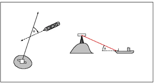
However, the RCS defines the echo at the radar for the model (target) in question, which
varies considerably depending on the target’s orientation, its relative distance and size
with respect to the simulated radar’s antenna. The viewing angles are shown in the
diagram below.
Figure A-19: Relative Azimuth (α) and Elevation (φ) Angles
RCS curves are normally produced using highly specialized off-line tools which input the
model geometry and material attributes (typically an OpenFlight file) and applies
corner detection, material absorption and so on to the geometric data representation of the
model. This processing is computationally expensive and is usually performed in non
real-time. The end-result of this computation (usually 2D arrays of data points in
elevation and azimuth) provides data that can be used more efficiently by simulation
modeling such as radar at run-time. Those data curves are stored in a polar-type
representation table, which provide specific reflectivity levels given a set of azimuth and
elevation aspect angles.
6.1
Functional Description
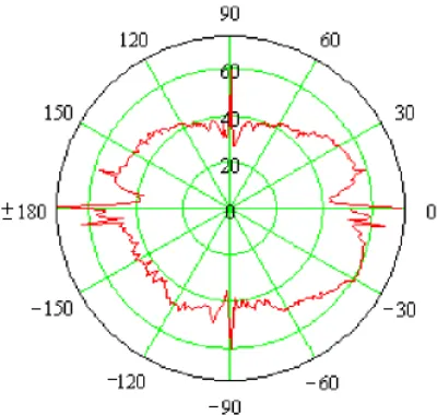
To simulate a target for most modes of operation, the Radar software uses an RCS Polar
Diagram as shown below:
Figure A-20: Polar Diagram of RCS data in Decibels at a given elevation angle
The polar diagram allows the radar to use an RCS value array (indexed by
azimuth/elevation angles) for getting an approximation of the overall RCS of distant
targets. The approximated RCS data is a function of the model’s materials, geometry,
view angles, and multi-paths reflections generated within the model itself.
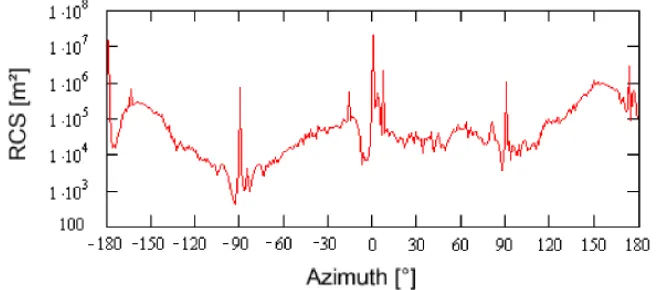
Figure A-21: Linear Diagram of RCS data in Decibels at a given elevation angle
As can be seen in the example above, relative intensities are much greater when viewing
the model directly in front (0° azimuth), from the back (±180° azimuth) and on the sides
(-90° and +90° azimuth).
The RCS data is often characterized by its data resolution and physical modeling
parameters. The data resolution determines the angular increments between successive
RCS values, and modeling parameters specify the attributes of the physical parameters
used to drive the RCS mathematical model computations (such as the Electro-Magnetic
properties of the simulated electric field).
Both wavelength and polarization affect how a radar system “sees” the elements in the
scene. Therefore, radar using different polarization and wavelength combinations may
provide different and complementary information, which can be used to enhance the
radar image in a specific way.
6.2
Wave Polarization
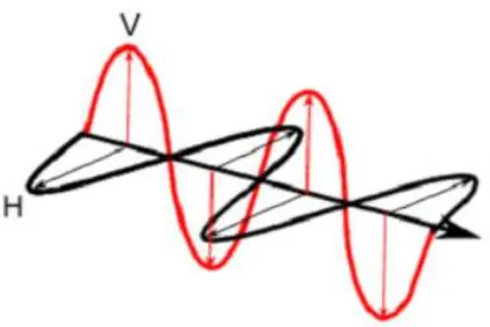
When computing an RCS model, it is important to consider microwave energy
propagation and scattering, and also the polarization of the radiation, which is an
important property. For a plane electromagnetic (EM) wave, polarization refers to the
locus of the electric field vector in the plane perpendicular to the direction of
Figure A-22: Horizontal and Vertical Polarization of a plane of EM wave
The waveform of the electric field strength (voltage) of an EM wave can be predictable
(the wave is polarized) or random (the wave is un-polarized), or a combination of both. In
the latter case, the degree of polarization describes the ratio of polarized power to total
power of the wave. An example of a fully polarized wave would be a monochromatic
sine wave, with a single, constant frequency and stable amplitude.
Many types of radar antennae are designed to transmit and/or receive microwave
radiation that is either horizontally (H) or vertically (V) polarized, or a combination of
both. A transmitted wave of either polarization can generate a backscattered wave with a
variety of polarizations, thus an equal amount of resulting RCS curves.
Polarization type on either transmission or reception mode can be synthesized by using H
and V components, with a well-defined relationship between them. For this reason,
systems that transmit and receive both of these linear polarizations are commonly used.
With these radars, there can be four combinations of transmit and receive polarizations:
HH - for horizontal transmit and horizontal receive
VV - for vertical transmit and vertical receive
HV - for horizontal transmit and vertical receive, and
VH - for vertical transmit and horizontal receive.
The first two polarization combinations are referred to as “like-polarized” because
transmit and receive polarization types are the same. The last two combinations are
referred to as “cross-polarized” because transmit and receive polarizations are orthogonal
to one another.
Single polarized
HH or VV (or possibly HV or VH)
Dual polarized
HH and HV, VV and VH, or HH and
VV
Alternating polarization
HH and HV, alternating with VV and
VH
Polarimetric
HH, VV, HV, and VH
Both wavelength and polarization affect how a radar system “sees” the elements in the
scene. Therefore, radar using different polarization and wavelength combinations may
provide different and complementary information, which can be used to enhance the
radar image in a specific way.
Therefore, polarization information is an important part of the CDB’s RCS Data
representation.
6.3
Wave Parameters
In addition to the wave polarization explained above, other physical parameters of the
modeled electromagnetic wave are also a contributing factor to the RCS of a target when
seen by Radar. Therefore those parameters are available in conjunction with the RCS
data curves:
Those parameters are generally as follows:
-
Radar Mode (Continuous wave or Pulsed)
-
Radiating Frequency
-
Antenna Main Lobe Gain
-
Antenna Main Lobe Bandwidth
-
Antenna Side Lobe 3dB point
-
Radar Pulse width (if pulsed radar mode)
-
Radar Pulse Repetition Frequency (if pulsed radar mode)
7.
RCS Data Model
7.1
Radar Cross Section Data Model
independent of frequency if operating in the far field region of the radar. The following
sections define the requirements for an RCS in a conformant CDB data store.
7.2
RCS Data Model
The CDB RCS data is organized so that client-devices can easily retrieve the following
information from the RCS model (Figure 7-1: Graphical Representation of the 3D Model
RCS Vector Data) below.
•
The modeling (physical) parameters that were used to generate the RCS polar data.
•
The RCS polar representation corresponding to one or more levels of resolution of
the RCS polar data.
•
The RCS polar representation corresponding to distinct radar mode of operation.
•
The RCS polar representation corresponding to a distinct radar model type.
RCS resolution refers to the angular pitch used in gathering RCS data for the model in
question. At a given RCS resolution, it is possible to have two or more RCS polar
representations due to the fact that the RCS data is computed based on a number of
physical modeling properties such as the characteristics of the electromagnetic beam, its
frequency, polarization, amplitude and phase. A simulated sensor operating in a given
mode of operation, over a given range of frequencies, will require the RCS data closest to
this mode. It will therefore need to use the closest matching Polar Diagram from the
RCS model data.
7.3
RCS Polar Diagram Data Representation using Shapefile
This section provides a detailed description of the content and format of RCS data for a
conformant implementation of a CDB data store.
7.3.1
Shapefile Internal Data Structure
Requirement 1
Req 1
req/cdb-radar/storage
Within a CDB, the RCS model SHALL be stored as a series of Esri’s ShapeFiles in
accordance with the Esri Shapefile Specification
2.
This section describes the vector data structure for the representation of RCS model data.
This format provides the required flexibility to create and visualize the RCS data
including:
2
•
Easy modification of data attributes
•
Simple visualization of RCS data in polar form
•
Allow irregular steps in azimuth/elevation (X/Y)
•
Allow some possibly missing values
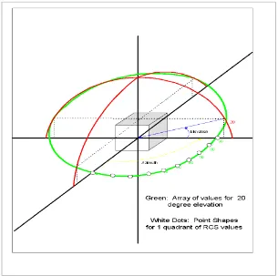
RCS data is inherently dimensional in nature and is naturally organized as a
two-dimensional array of RCS polar values computed at various azimuth and elevation angles
from the target. Each element of this array represents the RCS data value over each
uniformly distributed azimuth angle and distinct elevation angle.
Therefore, each of such array element can be represented as a “Point” geometry, with the
azimuth angle value (X) at a given elevation angle (Y), while at the same time storing the
associated attributes such as the RCS, Amplitude or Phase data in the instance attribute
database (dbf file) associated to the vector data, currently a Shapefile. Typical azimuth
angles would range between -180° and +180°, whereas the elevation angles would cover
from -90° to +90°. However, the RCS data set could potentially only cover just a partial
range of those angles if data is incomplete for example. This can be visualized in the
next diagram, showing RCS values at various azimuth angles corresponding to an
elevation angle of 20° with respect to the model (cube). Note that the axis conventions
follow those described in Section 6.3, Coordinate Systems.
Partial RCS data is permitted, i.e., it is permitted to cover a sub-region of the RCS polar
diagram with only points corresponding to known values.
For example, consider an RCS model consisting of data values in 5
oelevation increments
and 2
oazimuth increments covering the entire aspect angle range of the target. The CDB
representation would consist of (180°/5°)+1 = 37 sets of (360°/2°)+1 = 181 points
(vertices) for a full target aspect coverage; yielding 6697 point shapes with their attribute
data.
Requirement 2
Req 2
req/cdb-radar/storage-vertices
For each of the vector point vertices, the X component SHALL represent the azimuth
angle (equivalent to longitude) and the Y component SHALL represent the elevation
angle (equivalent to latitude); the RCS value (and other attributes) SHALL be stored in
the instance attributes within the DBF file.-azimuth
Requirement 3
Req 3
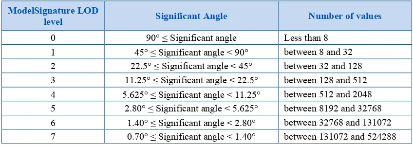
req/cdb-radar/storage-sig-angle
The eight prescribed values for azimuth and elevation increments SHALL be used for
specifying the ModelSignature Significant Angle. The table below shows the
correspondence between the ModelSignature LOD level number and the
ModelSignature Significant Angle.
Table 7-1: ModelSignature Significant Angle per LOD
ModelSignature LOD
level Significant Angle Number of values
0 90° ≤ Significant angle Less than 8
1 45° ≤ Significant angle < 90° between 8 and 32
2 22.5° ≤ Significant angle < 45° between 32 and 128
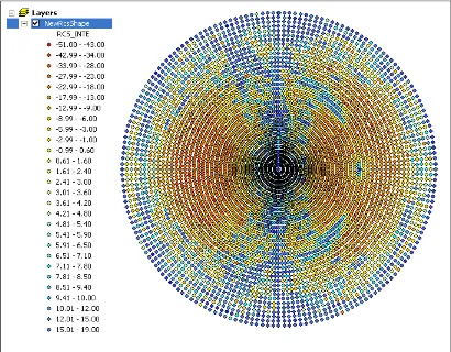
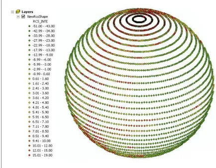
Such a data representation would typically produce the following diagram when viewed
in 2D (Figure 7-2: Polar Diagram of RCS Data in Planar Representation) and 3D (Figure
7-3: Polar Diagram of RCS Data in Spherical Representation) polar forms (color
representing the RCS Intensity attribute):
Figure 7-3: Polar Diagram of RCS Data in Spherical Representation
In addition, specific attributes within the vector data are required to specify other
characteristics of the RCS data, like EM polarization mode and frequency that were used
when characterizing the target’s RCS signature. Those are the class-level attributes and
are described below.
Requirement 4
Req 4
req/cdb-radar/attributes
The data for each distinct RCS representation model SHALL have two different types
of attributes; RCS model class attributes and RCS instance attributes as defined below.
values are logically re-grouped under a classname that stands for the entire
attributes specific to the RCS model. All of the classnames are re-grouped into a
model.dbf file referred to as the RCS Class Attribute file for the RCS model. (See
Section 7.4.1, Directory Structure). Each row of the model.dbf file corresponds to
a different classname. The first column of the file is the classname attribute and
acts as the primary key to access subsequent table entries; all other columns
correspond to the attributes represented by the classname.
2.
RCS Instance-level attribution: This is the data that represents a particular
instance of the RCS model for a RCS representation. The data is contained in the
attribution columns of the model.dbf file that accompanies the RCS’s *.shp file.
This *.dbf file is referred to as the RCS Instance Attribute file of the RCS model.
(See Section 7.4.1, Directory Structure). The first column of each row is always
the classname attribute. The other columns in a RCS Instance Attribute file are
used to describe further the associated shape.
Requirement 5
Req 5
req/cdb-radar/storage-files
In summary, for a single RCS model in the CDB, the data files SHALL consist of:
•
One *.shp main file that provides the geometric aspect (Points) for each data
instance of a RCS model.
•
Two *.dbf files (one instance-level on a-per RCS feature basis, and one
class-level at the RCS model class-level) that collectively provide the attribution for all of
the possible RCS models of a given RCS Model.
•
One *.shx index file that stores the file offsets and content lengths for each of the
records of the main *.shp file. The only purpose of this file is to provide a simple
means for clients to step through the individual records of the *.shp file (i.e., it
contains no CDB modeled data).
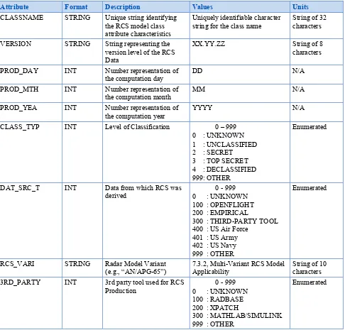
7.3.1.1
RCS Model Class-Level Attributes:
Many attributes within the vector data are required to specify the physical modeling
parameters corresponding to those used to produce the RCS data. These include, for
instance, the electromagnetic (EM) polarization mode and the frequency that were used
when characterizing the target’s RCS signature.
A description of the attribute information follows below. (The reader should keep in
mind that the 10-character limitation of attribute names is imposed by the dBASE III+
file format used by the Shapefile .DBF data format)
Table 7-2: XML Tags for Hot Spots
Attribute Format Description Values Units
CLASSNAME STRING Unique string identifying
the RCS model class attribute characteristics
Uniquely identifiable character string for the class name
String of 32 characters
VERSION STRING String representing the
version level of the RCS Data
XX.YY.ZZ String of 8
characters
PROD_DAY INT Number representation of
the computation day
DD N/A
PROD_MTH INT Number representation of
the computation month
MM N/A
PROD_YEA INT Number representation of
the computation year
DAT_SRC_T INT Data from which RCS was
derived
RCS_VARI STRING Radar Model Variant
(e.g., “AN/APG-65”)
7.3.2, Multi-Variant RCS Model Applicability
String of 10 characters
3RD_PARTY INT 3rd party tool used for RCS
Production
0 - 999 0 : UNKNOWN 100 : RADBASE 200 : XPATCH
300 : MATHLAB/SIMULINK 999 : OTHER
POL_TYPE INT Polarization Mode of RF
11 : ALTERNATING HH-HV 12 : ALTERNATING VV-VH 13 : POLARIMETRIC HH 14 : POLARIMETRIC VV 15 : POLARIMETRIC HV 16 : POLARIMETRIC VH 999: OTHER
Enumerated
EX_AMPL DOUBLE Transmitted Ex-component
amplitude level
INTENS_TY
EY_AMPL DOUBLE Transmitted Ey-component
amplitude level
INTENS_TY
EX_PHASE DOUBLE Transmitted Ex-component
phase
ANGL_TYP
EY_PHASE DOUBLE Transmitted Ey-component
phase
ANGL_TYP
EX_FREQ DOUBLE Transmitted Ex-component
frequency
FREQU_TY
EY_FREQ DOUBLE Transmitted Ey-component
frequency
ANGL_TYP INT RCS Angular Value units 0 : UNKNOWN
1 : DEGREES 2 : RADIANS 3 : GRADIANS 4 : STERADIANS
FREQU_TY INT RCS Frequency Value units 0 : UNKNOWN
TGT_TY INT Target Mode Value units 0 : UNKNOWN
1 : NORMAL
2 : SLIGHTLY DAMAGED 3 : DAMAGED
4 : DESTROYED
Enumerated
TIME_TY INT Time Value units 0 : UNKNOWN
1 : SECONDS 2 : MILLI-SECONDS 3 : MICRO-SECONDS
Enumerated
RF_TY INT RF Emission Mode Type 0 : UNKNOWN
1 : CONTINUOUS WAVE 2 : PULSED
Enumerated
LENGTH_TY INT Length Value units 0 – 999
0 : UNKNOWN
RF_FREQ DOUBLE Frequency of RF emission
used to characterize RCS
FREQU_TY
TGT_SS DOUBLE Significant size of input
Source Model Data
LENGTH_TY
MLOBEGAIN DOUBLE Antenna Main Lobe Gain INTENS_TY
MLOBEBW DOUBLE Antenna Main Lobe
Bandwidth
ANGL_TYP
SLOBE3DB DOUBLE Antenna Side Lobe 3dB
Point
ANGL_TYP
RF_PWIDTH DOUBLE RF Pulse Width TIME_TY
RF_PRF DOUBLE RF Pulse Repetition
Frequency
FREQU_TY
RCS_AVG_I DOUBLE RCS Intensity Average (or
mean) Value. This represents the arithmetic mean of the RCS table.
INTENS_TY
RCS_AVG_A DOUBLE RCS Amplitude Average (or
mean) Value. This represents the arithmetic
mean of the RCS table.
RCS_AVG_P DOUBLE RCS Phase Shift Average
(or mean) Value. This represents the arithmetic mean of the RCS table.
ANGL_TYP
RCS_NML_I DOUBLE Approximated RCS
Intensity Value for ‘Normal’ state
INTENS_TY
RCS_NML_A DOUBLE Approximated RCS
Amplitude Value for ‘Normal’ state
INTENS_TY
RCS_NML_P DOUBLE Approximated RCS Phase
Shift Value for ‘Normal’ state
ANGL_TY
RCS_SD_I DOUBLE Approximated RCS
Intensity Value for ‘Slightly Damaged’ state
INTENS_TY
RCS_SD_A DOUBLE Approximated RCS
Amplitude Value for ‘Slightly Damaged’ state
INTENS_TY
RCS_SD_P DOUBLE Approximated RCS Phase
Shift Value for ‘Slightly Damaged’ state
ANGL_TY
RCS_DMG_I DOUBLE Approximated RCS
Intensity Value for ‘Damaged’ state
INTENS_TY
RCS_DMG_A DOUBLE Approximated RCS
Amplitude Value for ‘Damaged’ state
INTENS_TY
RCS_DMG_P DOUBLE Approximated RCS Phase
Shift Value for ‘Damaged’ state
ANGL_TY
RCS_DST_I DOUBLE Approximated RCS
Intensity Value for ‘Destroyed’ state
INTENS_TY
RCS_DST_A DOUBLE Approximated RCS
Amplitude Value for ‘Destroyed’ state
INTENS_TY
RCS_DST_P DOUBLE Approximated RCS Phase
Shift Value for ‘Destroyed’ state
ANGL_TY
RCS_FLU_I DOUBLE RCS Intensity Fluctuation
(or Variance); the mean of all squared deviations from the mean for all RCS values.
N/A
RCS_FLU_A DOUBLE RCS Amplitude Fluctuation
(or Variance); the mean of all squared deviations from the mean for all RCS values.
N/A
Variance); the mean of all squared deviations from the mean for all RCS values.
RCS_SCINT DOUBLE This value specifies a level
of scintillation to be added to the simulated radar signature when model parts are being articulated.
7.3.3, Model’s Articulations Effect on RCS Data
INTENS_TY
RCS_FLASH DOUBLE RCS Intensity of Target
when viewed directly at 0˚ (face) or 180˚ (back) degrees azimuth. This “face” value is sometimes necessary when viewpoint turns around target and gets a “flash” at those specific angles.
INTENS_TY
EQ_SPH_RD DOUBLE Radius of an approximated
equivalent metallic sphere substituting the model
LENGTH_TY
MAX_VAL_I DOUBLE RCS Table Max Intensity
Value
INTENS_TY
MAX_VAL_A DOUBLE RCS Table Max Amplitude
Value
INTENS_TY
MAX_VAL_P DOUBLE RCS Table Max Phase Shift
Value
ANGL_TY
MIN_VAL_I DOUBLE RCS Table Min Intensity
Value
INTENS_TY
MIN_VAL_A DOUBLE RCS Table Min Amplitude
Value
INTENS_TY
MIN_VAL_P DOUBLE RCS Table Min Phase Shift
Value
ANGL_TY
AZ_SSANGL DOUBLE Azimuth smallest significant
delta angle
Smallest azimuth angle increment found in data
ANGL_TYP
EL_SSANGL DOUBLE Elevation smallest delta
significant angle
Smallest elevation angle increment found in data
ANGL_TYP
AZ_LSANGL DOUBLE Azimuth largest significant
delta angle
Smallest azimuth angle increment found in data
ANGL_TYP
EL_LSANGL DOUBLE Elevation largest significant
delta angle
Smallest elevation angle increment found in data
ANGL_TYP
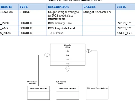
7.3.1.2
RCS Instance-Level Attribute Data
ShapeType = POINT
Values:
X coordinate is the Azimuth angle of the RCS sample
Y coordinate is the Elevation angle of the RCS sample
NOTE: The RCS of the model when viewed at +90° elevation (top view) is
significantly different than the one at -90° elevation (bottom view),
so there should be (180/EL_STEP)+1 point values to cover all
elevations. The azimuth, which has the same RCS value for +180°
and -180° will cover (360/AZ_STEP) point values.
Table 7-3: RCS Instance Attribute Fields
ATTRIBUTE TYPE DESCRIPTION VALUES UNITS
CLASSNAME STRING Unique string referring to
the RCS model class attribute name
String of 32 characters
RCS_INTE DOUBLE RCS Intensity Level INTEN_TY
RCS_AMPL DOUBLE RCS Amplitude Level INTEN_TY
RCS_PHAS DOUBLE RCS Phase ANGL_TYP
For a given RCS curve in a vector data set, an attribute “CLASSNAME” indicates which
type of sensor application the curve data is derived for, and under which resolution the
data was produced. Therefore, the single vector data set of the Model can regroup all
sensor data pertaining to various RCS signature types and resolutions for a given RCS
Model. Consider the next example. The vector data format therefore should not preclude
the capability to support multiple RCS curves simultaneously for a given model.
Figure 7-5: Example of RCS Vector Data
7.3.2
Multi-Variant RCS Model Applicability
Requirement 6
Req 6
req/cdb-radar/rcs-vari
Each variant of the RCS model in the vector data set SHALL have a 10-character string
attribute called “RCS_VARI”. The string may contain the specific Radar model
For example: The “AN/APG-65” Radar model name represents a Pulse Doppler X-Band
Multi-Mode Radar manufactured by Raytheon (Hughes) and used in F/A-18, AV-8B+
aircraft.
Table 7-4: Radar Model Numbers
AN/APA - Airborne Radar Auxiliary Assemblies
Model Number Description
AN/APA-1 Indicator Unit (Remote Repeater Scope) used with US Navy ASB radar
AN/APA-2 Radar Antenna Equipment
AN/APA-3 Radar Antenna Equipment
AN/APA-4 Radar Alarm Unit
AN/APA-5 Auxiliary Electronic Bombsight Equipment; used in P-2
AN/APA-6 Panoramic Radio Receiving Set; used with AN/APR-9 and AN/APR-14
AN/APA-7 Movie-Camera Photo Set
AN/APA-8 Video Amplifier; used with AN/APS-2
AN/APA-9 ECM Equipment; used in P2V-5
AN/APA-10 Panoramic Radio Receiving Set; used with AN/SPR-2
AN/APA-11 Panoramic Radio Receiving Set (Pulse Analyzer); used in B-52 EW pod, RC-121C, P2V-5, PBM-5S used with AN/APR-9 and AN/APR-14;
AN/APA-12 Sector Scan Antenna Adapter; used with AN/APS-2
AN/APA-13 Component of AN/APS-15
AN/APA-14 Component of AN/APS-15
AN/APA-15 Elevation Stabilizer; used with AN/APS-15
AN/APA-16 Auxiliary Electronic Bombsight Equipment used in PBY-6A
AN/APA-17 250-1000 MHz Broadband Direction Finding Radar (used with search receivers); manufactured by Hoffman Radio Corp., Aviola
AN/APA-19 Bombing Aid
AN/APA-21 Radar Bombing Compensating Unit
AN/APA-23 Automatic Tape Recorder; manufactured by Gamewell; used with AN/APR-1/2/4/5/6
AN/APA-24 50-280 MHz Direction Finding Radar (used with search receivers); manufactured by Heyer Products used in P4M-1Q
AN/APA-25 Radar Direction Finding Antenna Unit
AN/APA-26 S-Band Attenuator
AN/APA-27 Automatic Search & Jam Tuning Adapter
AN/APA-28 Multiple Indicator Equipment (6 displays); used with AN/APQ-13 AN/APA-29 Bombing Altitude Control Unit
AN/APA-33 Multiple Indicator Equipment (4 displays); used with AN/APQ-7
AN/APA-35 Radar Signal Recording Camera Unit
AN/APA-36 Remote Repeater Scope (modified AN/APA-1); used with AN/APQ-13 AN/APA-38 Panoramic Radio Receiving Set; used in PBM-5S
AN/APA-39 Radar Identification Unit
AN/APA-42 Bombing/Navigation System; used with AN/APS-23; used in XB-48 (see AN/APA-59)
AN/APA-43 Airborne Searchlight Control
AN/APA-44 Ground Position Indicator System; manufactured by Bell Telephone Lab; used with AN/ASB-3 and AN/APS-23/27/31 used in B-45 (together with AN/APS-23 to form AN/APQ-24), RB-66
AN/APA-45 Radar Antenna Tilt Stabilizer Unit
AN/APA-48 Radar Homing Equipment, 140-300 MHz; manufactured by RRL AN/APA-49 Radar Bombing Ground Position Indicator
AN/APA-50 Low Altitude Rocket Bombing Unit AN/APA-51 Radar Indicator Unit
AN/APA-52 X-Band TACAN Doppler Navaid; used in F-8, SB-29 AN/APA-54 Radar Recorder Group (SHORAN); used in B-57
AN/APA-55 Radar Adapter Unit
AN/APA-56 Radar Display Console; used with AN/APS-45/95; used in EC-121 AN/APA-57 Ground Position Indicator Group; used in AF-2W, P-2, S-2; replaced by
AN/ASA-13
AN/APA-58 Ground Position Computer
AN/APA-59 Bombing/Navigation Computer "SRC-1"; manufactured by Sperry; used in B-36, XB-48
AN/APA-60 Autopilot
AN/APA-61 Radar Bombing Navigational Computer
AN/APA-62 Panoramic Receiver
AN/APA-63 Autopilot
AN/APA-64 Radar Signal Analyzer used in P2V-4
AN/APA-66 Radar Monitor
AN/APA-69 Direction Finding Radar Set; used in RB-57D, A-1, C-47, P-2, P-5, S-2, RC-121C, Z-1, ZPK
AN/APA-70 Direction Finder Group; used with AN/APR-9; used in AF-2W, P-2, S-2, TBM-3S
AN/APA-72 Signal Analyzer; used in E-2
AN/APA-74 Pulse Analyzer Group; manufactured by Loral; used in EB-66, A-3, EC-47, P-2, P-5, Z-1, ZPK; replaced AN/APA-11
AN/APA-80 Control & Guidance Monitoring Group; used in AUM-N-2, HSL-1, P-2, P-5, S-2
AN/APA-81 Ground Position Indicator Group; used with AN/APS-20; used in AF-2W, EC-121
AN/APA-82 Direction Finder Group; used in B-52, C-130, C-133, C-135
AN/APA-84 Radar Intercept Targeting Computer; used with APG-37; used in F-86D/K AN/APA-85 Control-Indicator Group; used with AN/APS-42 used in R6D-1
AN/APA-89 Coder Group; used in A-3, UH-1E
AN/APA-90 Indicator Group; used with AN/APW-11; used in B-57, B-66
AN/APA-91 used with AN/APS-33
AN/APA-92 ECM Set
AN/APA-94 Signal Analyzer
AN/APA-106 Bomb Damage Evaluation Group; used with AN/APQ-24; used in B-50D AN/APA-109 Radar Control; manufactured by Westinghouse
AN/APA-113 used with AN/APS-62
AN/APA-122 Radar Set
AN/APA-125 Radar Display; used with AN/APS-80/82, AN/ASA-47; used in P-2H, P-3A, P-5, E-1
AN/APA-126 Doppler Equipment; used in A-7
AN/APA-127 Sparrow Missile Fire Control System; manufactured by Raytheon; used in F-3, F-4B/C
AN/APA-128 Sparrow Missile Radar Set Group; manufactured by Raytheon; used with AN/AWG-7; used in XF8U-3, F-4
AN/APA-138 Radar Display; used with AN/AWG-7; used in XF8U-3 AN/APA-141 Radar Set; used in B-52G/H
AN/APA-143 Rotodome Antenna Group; manufactured by Dalmo Victor; used with AN/APS-96; used in E-2A/B
AN/APA-144 Signal Analyzer Group; used in EA-1F, EC-121M, P-3A AN/APA-150 Station Keeping System; used in SH-34J
AN/APA-153 Cable Breakout Adapter Set; manufactured by AC Spark Plug; used with AN/APS-104
AN/APA-157 Continuous Wave Illuminator (for AIM-7 targeting); manufactured by Raytheon; used in F-4B/C
AN/APA-159 Radar Set Group; manufactured by Hazeltine; used in EC-121D/H AN/APA-160 Test Adapter; manufactured by Sperry; used with AN/APN-42 AN/APA-161 Station Keeping System used in ASW helicopters
AN/APA-162 Map Matcher
AN/APA-164 Rotodome; used with AN/APS-111; used in E-2A/B
AN/APA-165 Intercept Computer (for AIM-9 firing); manufactured by Raytheon; used with AN/APQ-109 used in F-4D
AN/APA-167 used with AN/APG-53
AN/APA-170 Radar Set
AN/APA-171 Rotodome Antenna Group; used with AN/APS-120, AN/APX-76; used in E-2C
AN/APA-172 Control Indicator Group; used with AN/APS-120, AN/APX-76; used in E-2C
AN/APA-173 Test Bench
AN/APB - Airborne Bombing Radars
Model Number Description
AN/APB-1 Radar Beacon
AN/APB-2 Bombing Radar; used in B-58
AN/APD - Airborne Direction Finding and Surveillance Radars
Model Number Description
AN/APD-1 Homing Radar; used in TBF/TBM
AN/APD-4 D/E/F-Bamd Radar Direction Finding System; manufactured by ITT; used in RB-47H, B-52, EB-66C
AN/APD-5 Reconnaissance Radar
AN/APD-7 Radar Surveillance System; manufactured by Westinghouse; used in OV-1D, RA-5C
AN/APD-8 Side-Looking Reconnaissance Radar; manufactured by Westinghouse; proposed for RF-111A
AN/APD-9 Radar Set
AN/APD-10 Side-Looking Reconnaissance and Mapping Radar; used in F-4, RF-4B/C, CP-140;
special tests in NC-141, C-130
AN/APD-11 Side-Looking Radar Reconnaissance Set; part of AN/UPD-6; used in RF-4E AN/APD-12 I/J-band Side-Looking Reconnaissance System; manufactured by Lockheed
Martin;
part of AN/UPD-8 and AN/UPD-9; used in Israeli RF-4B
AN/APD-13 QUICK LOOK Electronic Intelligence Subsystem; manufactured by Systems & Electronics; used in "Guardrail" RC-12
AN/APD-14 SAROS (SAR for Open Skies) Radar System; manufactured by Sandia; part of AN/UPD-8; used in OC-135
AN/APD-501 Maritime Patrol Radar; used in Lancaster (Canada)
AN/APG - Airborne Fire Control Radars
Model Number Description
AN/APG-1 S-Band Intercept Radar used in P-61B
AN/APG-2 S-Band Intercept & Gun Laying Radar used in P-61
AN/APG-3 Tail Gun Laying Radar; manufactured by General Electric used in B-29 and B-36B
AN/APG-4 L-Band Low Altitude Torpedo Release Radar "Sniffer" used in TBM AN/APG-5 S-Band Gun Laying/Range-Finding Radar used in B-17, B-24 and F-86A
(AN/APG-5C)
AN/APG-6 L-Band Low Altitude Bomb Release Radar "Super Sniffer" (improved AN/APG-4)
AN/APG-7 Glide Bomb Control Radar "SRB" (Seeking Radar Bomb) AN/APG-8 S-Band Turret Fire Control Radar used in B-29B
AN/APG-9 L-Band Low Altitude Bomb Release Radar (improved AN/APG-6)
AN/APG-10 Weapons System Radar
AN/APG-11 L-Band Toss Bombing Radar
AN/APG-12 L-Band Low Altitude Bomb Release Radar (improved AN/APG-9)
AN/APG-13 S-Band Nose Gun Laying Radar "Falcon"; manufactured by General Electric used with 75mm nose gun of B-25H
AN/APG-14 S-Band Gun Sight Radar used in B-29 AN/APG-15 S-Band Tail Gun Radar used in B-29B, PB4Y
AN/APG-16 X-Band Gun Laying Radar (modification of AN/APG-2) used in B-32, XB-48 AN/APG-17 S-Band Low Altitude Bomb Release Radar (improved AN/APG-4)
AN/APG-19 X-Band Fire Control Radar; manufactured by Martin (improved AN/APG-8 and -18)
AN/APG-20 S-Band Low Altitude Bomb Release Radar (improved AN/APG-6)
AN/APG-21 Ground-Ranging Radar
AN/APG-22 X-Band Gun Sight Radar; manufactured by Raytheon used with Mk.18/23 Lead-Computing Gun Sights
AN/APG-23 Weapons System Radar used in B-36A AN/APG-24 Weapons System Radar used in B-36B AN/APG-25 X-Band Gun Tracking Radar used in F-100
AN/APG-26 Weapons System Tracking Radar; manufactured by Westinghouse used in F3D
AN/APG-27 Tail Gun Radar used in XB-46 and XB-48
AN/APG-28 Intercept Radar (modified AN/APG-1) used in F-82F
AN/APG-29 Night/All-Weather Fighter Fire-Control Radar (for Type D-1 Fire-Control System)
AN/APG-30 X-Band Fire Control Radar; manufactured by Sperry used in B-45, B-57, F-4E, F-8A, F-8F-4E, F-86A (final blocks only), F-86E/F, F-100, FJ-2, F2H-2
AN/APG-31 Gun Laying Radar; manufactured by Raytheon used in B-57
AN/APG-32 X-Band Tail Turret Autotrack Radar; manufactured by General Electric used in B-36D/F, B-47E
AN/APG-33 X-Band Fire Control Radar; manufactured by Hughes used in TB-25K, F-94A/B, F-89A
AN/APG-34 Computing Radar Gunfight used in F-104C
AN/APG-35 Radar used in F3D
AN/APG-36 Search Radar used in F2H-2N, F-86D (replaced by AN/APG-37) AN/APG-37 Search Radar; manufactured by Hughes used in F-86D/K/L, F2H-4 AN/APG-39 Gun Laying Radar used in B-47E
AN/APG-40 Fire Control Radar; manufactured by Hughes used in TB-25M, F-94C, F-89D, CF-100 (Canada)
AN/APG-41 Tail Gun Radar (twin radomes); manufactured by General Electric used in B-36H
AN/APG-43 Continuous Wave Interception Radar; manufactured by Raytheon AN/APG-45 Fire-Control Radar (miniaturized AN/APG-30); manufactured by General
Electric; intended for patrol aircraft gun turrets AN/APG-46 Fire-Control Radar; tested in A-6A
AN/APG-48 Airborne Fire-Control System Mk.22 AN/APG-50 Intercept Radar used in F-4
AN/APG-51 Intercept Radar; manufactured by Hughes used in F3H-2, F3D AN/APG-53 Weapons System Radar; manufactured by Stewart-Warner used in A-4 AN/APG-55 Pulse Doppler Intercept Radar; manufactured by Westinghouse
AN/APG-56 Fire Control Radar (similar to AN/APG-30) used in F-86 (only Australian models with A-4 gun sight)
AN/APG-57 Fire-Control Radar; manufactured by Gould
AN/APG-59 Pulse-Doppler Gunnery Radar; manufactured by Westinghouse; part of AN/AWG-10 used in F-4J
AN/APG-61 Fire-Control Radar; part of AN/AWG-12 used in F-4M
AN/APG-63 Pulse Doppler X-Band Fire Control Radar (AN/APG-63(V)2 is an AESA variant); manufactured by Raytheon (Hughes) used in F-15A/B/C/D/H/K
AN/APG-64 Fire-Control Radar (development of AN/APG-63); not produced AN/APG-65 Pulse Doppler X-Band Multi-Mode Radar; manufactured by Raytheon
(Hughes) used in F/A-18A/B, F-4 ICE/Peace Ikarus 2000, AV-8B+ (upgraded)
AN/APG-66 Pulse Doppler X-Band Multi-Mode Radar; manufactured by Northrop Grumman (Westinghouse) used in F-16A/B, F-4EJ (Japan), Hawk 200 (UK) AN/APG-67 Pulse Doppler X-Band Multi-Mode Radar; manufactured by Lockheed Martin
(General Electric) (Model G-200) used in F-20, A-50 (Korea), F-5-2000 (Taiwan), Ching Kuo (Taiwan)
AN/APG-68 Pulse Doppler X-Band Multi-Mode Radar (improved AN/APG-66); manufactured by Northrop Grumman (Westinghouse) used in F-16C/D-30/40/50
AN/APG-69 Radar Set; manufactured by Emerson used in F-5E, AV-8?
AN/APG-70 Pulse Doppler X-Band Multi-Mode Radar (upgrade of AN/APG-63); manufactured by Raytheon (Hughes) used in F-15C/D/E
AN/APG-71 Pulse Doppler X-Band Multi-Mode Radar; manufactured by Raytheon (Hughes) used in F-14D
AN/APG-73 Pulse Doppler X-Band Multi-Mode Radar (upgrade of AN/APG-65); manufactured by Raytheon (Hughes) used in F/A-18C/D/E/F
AN/APG-74 Pod-mounted Radar System; manufactured by Northrop Grumman (Norden) AN/APG-76 Pulse Doppler Ku-Band Multi-Mode Radar; manufactured by Northrop
Grumman (Norden) used in F-4E (Israel); tested in pod with F-16, S-3B AN/APG-77 Pulse Doppler X-Band AESA (Active Electronically Scanned Array)
Multi-Mode Radar; manufactured by Northrop Grumman/Raytheon used in F/A-22A
AN/APG-78 Fire Control Radar "Longbow"; manufactured by Northrop Grumman & Lockheed Martin used on mast in AH-64D, RAH-66, underwing on AH-1W/Z AN/APG-79 AESA (Active Electronically Scanned Array) Multi-Mode Radar (based on
AN/APG-73); manufactured by Raytheon used in F/A-18E/F/G as replacement for AN/APG-73
AN/APG-80 "Agile Beam Radar" AESA (Active Electronically Scanned Array) Multi-Mode Radar (based on AN/APG-68); manufactured by Northrop Grumman; intended for F-16E/F
AN/APG-81 AESA (Active Electronically Scanned Array) Radar planned for F-35 AN/APG-501 X-Band Ranging Radar used in F-86
AN/APG-T1 Radar Training Set for AN/APG-1
AN/APN - Airborne Navigation Radars
Model Number Description
AN/APN-1 Radio Altimeter (improved AN/ARN-1) used in P-61, C-119, B-32, C-121, H-19, P-5, AF-2W, AD-5, F2H-2/2N/2P, F3D, F6F-5N, F9F, XF10F-1, P2V-4, PB4Y-2, PBM-5S, PBY-6A, R5C-1, R5D-2, R6D-1, SB2C-5, TBM-3S AN/APN-2 "Rebecca" Radio Beacon used with AN/PPN-1, AN/TPN-2
AN/APN-3 SHORAN used with AN/CPN-2 used in B-45A
C-121, P2V-4, PBM-5S, PBY-6A, PB4Y-2, R4Q-1, R6D-1 AN/APN-5 Radar Beacon Navigation Aid used in F-86
AN/APN-6 S-Band Beacon used with AN/PPN-10, AN/PPN-11
AN/APN-7 LORAN S-Band Beacon used with AN/APS-2
AN/APN-8 Radar Beacon
AN/APN-9 LORAN; manufactured by RCA used in B-29, B-32, RC-121, C-97 replaced AN/APN-4
AN/APN-10 "Rebecca" Interrogation Set
AN/APN-11 X-Band Beacon used with AN/APS-3/4/6/10/15/31/33 used in B-47, KC-97, XS-1
AN/APN-12 Rendezvous Radar (or 160-230 MHz "Rebecca" Interrogator) used in B-47, C-97
AN/APN-13 S-Band Beacon (improved AN/APN-7)
AN/APN-14 Navigation Aid
AN/APN-15 Low Level Altimeter Set; manufactured by Sperry used in B-52, CH-3C
AN/APN-16 Radar Beacon
AN/APN-18 Radar Beacon
AN/APN-19 "Rosebud" S-Band Beacon used in F-82D
AN/APN-20 Radar Beacon
AN/APN-21 Radar Beacon
AN/APN-22 Radar Altimeter; manufactured by Electronic Assistance Corp used in A-3, B-66, C-119, RC-121, C-130, RF-101C, OV-1, AD-5, P2V-5, R6D-1
AN/APN-23 Active Seeker used in KAY-1(XSAM-N-4)
AN/APN-24 Navigation Set
AN/APN-25 Doppler Navigator; manufactured by GPI
AN/APN-26 SG-Band (VHF) Beacon
AN/APN-29 SG-Band (VHF) Beacon
AN/APN-30 Radar Beacon
AN/APN-33 S-Band Beacon; replaced AN/APN-7 used in XSSM-N-8 AN/APN-34 Distance Measuring Radar used in C-97C, R6D-1
AN/APN-35 Radar Beacon
AN/APN-41 Missile Beacon for LTV-N-2 replaced AN/APN-33 AN/APN-42 Radar Altimeter used in WC-130, WB-47E, B-52 AN/APN-45 Tracking Radar Beacon used in DC-130A
AN/APN-46 Radar Beacon
AN/APN-47 Radar Beacon
AN/APN-48 Radar Beacon
AN/APN-49 Radar Beacon
AN/APN-50 Navigation Radar; manufactured by Sperry
AN/APN-54 Radar Beacon
AN/APN-55 Radar Beacon (for missiles)
AN/APN-56 Navigation Radar; manufactured by Gould AN/APN-57 Ground Position Indicator
AN/APN-58 Navigation Radar; manufactured by Sperry
AN/APN-59 Search & Weather Radar; manufactured by Sperry used in C-130, C-135, B-57, C-133, C-141, KC-97
AN/APN-60 S-Band Beacon used in B-52 AN/APN-61 Radar Beacon used in XF-85
AN/APN-63 S-Band (Receive)/L-Band (Transmit) Beacon; manufactured by Melpar AN/APN-66 Doppler Navigation Radar used in SM-62, B-47
AN/APN-67 Doppler Set used in P6M-1, NC-121 "Project Magnet", USN helicopters; tested in P-2
AN/APN-68 IFF Beacon used with AN/APX-6
AN/APN-69 X-Band Rendezvous Beacon used in B-47, B-52, C-97, RB-57D, KC-135 used with AN/APN-59
AN/APN-70 LORAN; manufactured by Dayton Aviation Radio & Equip Corp used in B-50, C-54, C-119, C-121, RC-121D, C-130, C-135, P-2, P-3A, T-29C/D, Z-1, R6D-1
AN/APN-71 Flare-Out Unit
AN/APN-75 Rendezvous Radar used in B-47
AN/APN-76 Rendezvous Radar; manufactured by Olympic used in KC-97, B-47B/E AN/APN-77 Doppler Set used in SZ-1B, USN helicopters
AN/APN-78 Doppler Set used in helicopters
AN/APN-79 Doppler Set manufactured by Teledyne Ryan used in helicopters AN/APN-81 Doppler Set used in RB/WB-66, WB-50, C-130, KC-135
AN/APN-82 Doppler Navigation Radar (combination of AN/APN-81 and AN/ASN-6) used in EB/RB/WB-66, KC-135
AN/APN-84 SHORAN Set; manufactured by Hazeltine used in RC-130A AN/APN-85 Navigation Radar; manufactured by Hazeltine
AN/APN-89 Doppler Set; part of AN/ASQ-38 used in B-52E/G/H
AN/APN-90 Doppler Set
AN/APN-91 Tracking Beacon used in BQM-34C
AN/APN-92 Navigation Radar
AN/APN-96 Doppler Set
AN/APN-97 Doppler Set; manufactured by Ryan used in UH-2A, SH-3, SH-34J
AN/APN-99 Doppler Navigation Set (combination of AN/APN-81 and AN/ASN-7) used in B-52, AC-130A, KC-135
AN/APN-100 Radar Altimeter; manufactured by Litton used in CH-47A
AN/APN-101 Airborne Radar used in RF-4C, F-4E (possible confusion with AN/ARN-101) AN/APN-102 Doppler Set; manufactured by GPI used in RB-47, 47E, RB-57F,
WB-57F, F-100C/F, RF-101 AN/APN-103 Navigational Computer System
AN/APN-105 All-Weather Doppler Navigation System; manufactured by LFE used in F-105B/D, T-39B
AN/APN-108 Doppler Set (derivative of 89 with gyro components from AN/APN-81) used in B-52E
AN/APN-109 Altimeter; manufactured by Honeywell
AN/APN-110 Doppler Navigation Set used in B-58, F-100D/F, RF-101 AN/APN-113 Doppler Radar; part of AN/ASQ-42 used in B-58
AN/APN-114 Automatic Landing System used with AN/GSN-5; tested in TF-102
AN/APN-115 Navigation Radar; manufactured by General Electric
AN/APN-116 Doppler Set
AN/APN-117 Low-Level Radar Altimeter (in combination with AN/APN-22); manufactured by Electronic Assistance Corp used in A-6A, P-2, S-2, SH-3A, H-13H, CH-47A, HH-52, CH-53A
AN/APN-118 Doppler Navigation Set
AN/APN-119 Doppler Set
AN/APN-120 Radar Altimeter; planned for A-5, A-6A, but not produced
AN/APN-122 Doppler Navigation Set used in S-2, A-2, A-3, A-4, A-6, RA-5C, C-47, C-54, EC-121, E-2, TF-8, P-2, P-3, P-5
AN/APN-126 Doppler Set
AN/APN-127 Collision Warning System
AN/APN-128 Navigation Radar; manufactured by Teledyne used in C-130
AN/APN-129 Doppler Navigation System; manufactured by Teledyne used in OV-1A/B AN/APN-130 Doppler Radar; manufactured by Teledyne Ryan used in UH-2, SH-3, SH-34J,
CH-53D, Z-1
AN/APN-131 Doppler Navigation Radar used in F-105, T-39B, TF-8A
AN/APN-132 X-Band Beacon; manufactured by Motorola used in BQM-34A, QF-9G AN/APN-133 High-Altitude Radar Altimeter (upgraded SCR-728) used in C-130, C-135 AN/APN-134 Ku-Band Beacon; manufactured by Bendix used in KC-135
AN/APN-135 X-Band Beacon (for in-flight refueling); manufactured by Bendix used in B-58
AN/APN-136 Ku-Band Beacon (for in-flight refueling); manufactured by Bendix used in B-58
AN/APN-140 Radar Altimeter
AN/APN-141 Low Altitude Radar Altimeter; manufactured by Bendix used in A/TA-4, A-6, A-7, C-2, C-130, C-141, E-2C, F-4, F-8, F-104, F-105, P-3, S-2, T-39, SH-3 AN/APN-142 Navigation Radar used in F-4C
AN/APN-144 Doppler Navigation Radar used in EC-121, VC-137 AN/APN-145 LORAN C Set used in RC-135D
AN/APN-146 Radar Altimeter
AN/APN-147 Doppler Navigation System; manufactured by Canadian Marconi used in AC-119, C-124C, C-130, WC-130B/E, RC-135A, WC-135B, C-135F, C-141 AN/APN-148 Doppler Navigation Radar used in F-105D/F
AN/APN-149 Terrain Avoidance Radar used in TF-8
AN/APN-150 Radar Altimeter used in CH-3C, B-52, C-130, EC-130E, C-135
AN/APN-151 LORAN C Receiver; manufactured by ITT used in RC-135B, C-141A, H-3
AN/APN-152 LORAN C Receiver
AN/APN-154 X-Band Beacon Augmenter (Tracking Beacon); manufactured by Motorola used with AN/TPB-1, AN/TPQ-10 used in A-4, A-7, F-14, A-6, AH-1T, H-46, CH-53
AN/APN-155 Low Altitude Radar Altimeter; manufactured by Stewart-Warner used in F-4 AN/APN-157 LORAN C Receiver; manufactured by ITT used in C-130, RC-135B, C-141,
P-3C, EP-3E
AN/APN-158 Weather Radar; manufactured by Collins used in HC-123B, U-8F, U-21A, CV-2
AN/APN-159 Radar Altimeter; manufactured by Stewart-Warner used in RF-4
AN/APN-161 High-Resolution Mapping Radar; manufactured by Sperry used in C-130 AN/APN-162 manufactured by Canadian Marconi
AN/APN-163 Doppler Navigation System
AN/APN-165 Terrain-Following/Ground-Mapping Radar; manufactured by Texas Instruments used in OV-1
AN/APN-167 Radar Altimeter; manufactured by Honeywell used in F/FB-111A
AN/APN-168 Doppler Radar; manufactured by Canadian Marconi used with AN/AYA-3 used in CH-53A, OV-1
AN/APN-169 Station-Keeping Radar; manufactured by Sierra Research used in 130, C-141
AN/APN-170 Terrain Following Radar; manufactured by General Dynamics; tested in A-4C, B-52, B-58
AN/APN-171 Radar Altimeter; manufactured by Honeywell used in C-130, E-2C, SH-2F, SH-3H, OH-6A, CH-46, CH-53
AN/APN-172 Doppler Set; manufactured by Marconi used with AN/ASN-73 used in HH-53C, CH-53G
AN/APN-174 Station-Keeping Subsystem; manufactured by Teledyne used in 46, CH-53
AN/APN-175 Doppler Radar used in C-130, CH-3B, HH-3E, MH-53
AN/APN-176 Radar Altimeter; manufactured by Texas Instruments used in FB-111A AN/APN-177 Doppler Altimeter
AN/APN-178 Navigation Radar; manufactured by Sierra used in C-130
AN/APN-179 Doppler Navigation Radar; manufactured by Bendix used in EC-47
AN/APN-180 LORAN A Automatic Tracking Receiver used with AN/AYN-1 used in HH-3F
AN/APN-181 LORAN C/D Receiver
AN/APN-182 Doppler Radar Navigation System; manufactured by Ryan used with AN/AYK-2 used in SH-3H, CH-46, HH-46A/D, SH-2D, UH-2C, RH-53 AN/APN-184 Radar Altimeter; manufactured by Bendix used in C-130, Hawker P-1127
(UK)
AN/APN-185 Doppler Navigation Radar; manufactured by Singer-Kearfott used in FB-111A, A-7D, B-1A
AN/APN-186 Doppler System; tested in A-6 ILAAS (AN/ASQ-116)
AN/APN-187 Doppler Navigation Radar; manufactured by Singer-Kearfott used in P-3 AN/APN-189 Doppler Navigation Radar; manufactured by Marconi used in F-111D AN/APN-190 Doppler Radar; manufactured by Singer-Kearfott used in A-7, AC-130E,
F-111
AN/APN-192 Short-Pulse Radar Altimeter; manufactured by Teledyne used in CH-47 AN/APN-193 Doppler Velocity Sensor; manufactured by Ryan
AN/APN-194 Radar Altimeter; manufactured by Honeywell used in F-14, A-6E, AH-1W, HH-60H, EA-6B, AV-8B, C-2A, P-3C, EP-3E, F/A-18, SH-60B/F, T-45A, TA-4J, TC-130G, S-3, A-4, A-7, A-10, B-1, TC-4C, QF-4, BQM-8D/F, MQM-8G, BQM-34S, AQM-34U, RGM/UGM-109B
AN/APN-195 Nose-Mounted Radar; manufactured by Collins used in SH-3D, HH-3E AN/APN-196 Doppler Radar used in F-105
AN/APN-197 STATE Airborne Station; manufactured by Honeywell used with AN/TPN-21, AN/UPN-33; tested in C-123, C-131, T-39, CH-3
AN/APN-198 Radar Altimeter; manufactured by Honeywell used in F-104G, AV-8, Sea King (UK), Lynx (UK)
AN/APN-199 LORAN Receiver; manufactured by Collins used in C-5A
AN/APN-200 Doppler Velocity Sensor; manufactured by Teledyne used in B-1, E-3, S-3
AN/APN-201 Radar Altimeter; manufactured by Hoffman Electronics used in S-3 AN/APN-202 Radar Beacon; manufactured by Motorola used with AN/SPN-46 ACLS
(Automatic Carrier Landing System) used in AV-8B, F/A-18, S-3, C-2, P-3C AN/APN-203 Radar Altimeter; manufactured by Stewart-Warner used in T-43A
AN/APN-205 Doppler Radar; manufactured by Teledyne used in SH-2, SH-60B AN/APN-206 Doppler Set used in B-1A
AN/APN-208 Doppler Navigation Radar; manufactured by Marconi used in HH-53H, Bell 412
AN/APN-209 Radar Altimeter; manufactured by Honeywell/Stewart-Warner used in AH-1F, UH-1V, CH-47D, OH-58C/D, H-60, T-43A
AN/APN-210 Doppler Set; manufactured by Singer used in CH-53G
AN/APN-211 Navigation Radar; manufactured by Teledyne-Ryan used in helicopters AN/APN-213 Doppler Velocity Sensor; manufactured by Litton (Teledyne-Ryan) used in
E-3; tested in KC-135
AN/APN-214 Radar Altimeter
AN/APN-215 Weather & Search Radar; manufactured by Bendix/King used in R38A, U-21, C-130
AN/APN-217 Doppler Radar Navigation Sensor; manufactured by Litton (Teledyne-Ryan) used in AH-1W, UH-1N, SH-2G, SH-3D, HH-3F, CH-46, CH-53E, MH-53E, RH-53D, HH-60H/J, SH-60B/F/J, V-22
AN/APN-218 Doppler Radar Navigation System; manufactured by Litton (Teledyne-Ryan) used in B-1B, B-52G/H, KC-135, C-130, F-111G
AN/APN-220 Doppler Radar; manufactured by Teledyne-Ryan
AN/APN-221 Doppler Radar (derived from AN/APN-208); manufactured by Marconi used in C-141, HH-53H, MH-53J
AN/APN-222 Radar Altimeter; manufactured by Honeywell used in C-130, E-6A AN/APN-224 Radar Altimeter; manufactured by Honeywell used in B-52G/H, B-1B AN/APN-227 Doppler Radar used in P-3C
AN/APN-230 Doppler Navigation Radar (improved AN/APN-218) used in B-1B
AN/APN-231 Radar Navigation System; manufactured by Teledyne-Ryan used in EA-6A AN/APN-232 CARA (Combined Altitude Radar Altimeter); manufactured by Gould used in
C-5, C-17, C-130, OC-135, C-141, F-16
Teledyne-Ryan used in C-2, OV-10D, CH-47, S-2, Alpha Jet (Germany), DHC-5
AN/APN-234 Weather and SAR Radar (Model RDR-1400C; improved AN/APN-215); manufactured by Telephonics (originally by Bendix/King) used in P-3, C-2 AN/APN-235 Doppler Navigation Set (development of AN/APN-221) used in HH-60A AN/APN-236 Doppler Radar System; manufactured by Teledyne
AN/APN-237 Ku-Band Terrain-Following Radar; manufactured by Texas-Instruments; part of AN/AAQ-13
AN/APN-238
AN/APN-239 Weather and SAR Radar (Model RDR-1400C, similar to AN/APN-234); manufactured by Telephonics (originally by Bendix/King) used in HH-60G, MH-60G
AN/APN-240 Station-Keeping System; manufactured by Sierra Research; replaced AN/APN-169
AN/APN-241 Weather & Navigation Radar; manufactured by Northrop Grumman (Westinghouse) used in C-130H/J, C-27J, HS-748 (Australia)
AN/APN-242 Weather & Navigation Radar; manufactured by Sperry; replacement for AN/APN-59
AN/APN-243 Station-Keeping Equipment; manufactured by Sierra Technologies used in C-17, C-130J
AN/APN-244 E-TCAS (Enhanced Traffic Alert Collision Avoidance System); manufactured by Honeywell (AlliedSignal) used in C-130E/H/J
AN/APN-245 Radar Beacon used with ACLS (Automatic Carrier Landing System) AN/SPN-46 used in F/A-18
AN/APN-501 Doppler Radar used in C-141(?) AN/APN-503 Doppler Radar used in CP-121 (Canada)
AN/APN-509 Radar Altimeter
AN/APN-510 Doppler Navigation System used in CP-140 (Canada)
AN/APN-511 Radar Altimeter
AN/APN-512 Radar Altimeter used in CC-130E/H (Canada)
AN/APN-513 Doppler Radar Navigation Set used in CH-124A (Canada) AN/APN-T6 Radar Interpretation Trainer
AN/APN-T8 Doppler System Trainer used with C-5 AN/APN-T10 Radar Trainer used with C-5
AN/APQ - Airborne Multipurpose/Special Radars
Model Number Description
AN/APQ-1 Radar Jammer RT-26
AN/APQ-2 450-750 MHz High Power Barrage Jamming Transmitter "Rug"; manufactured by General Motors (Delco Div.) used in PB4Y-2 AN/APQ-3 S-Band Radar Receiver; later redesignated AN/APR-5
AN/APQ-4 Panoramic Radar Receiver; later redesignated AN/APR-6
AN/APQ-5 Low Level Radar Bombsight; manufactured by Western Electric used with AN/APS-2/3/15 used in B-24, B-25, B-32, PBJ, PBM
AN/APQ-8 Deception Radar "Spoofer"
AN/APQ-9 475-585 MHz High Power Barrage Jamming Transmitter "Carpet III"; manufactured by General Motors (Delco Div.)
AN/APQ-10 X-Band High Altitude Bombing Radar "Eagle Mk.2"; manufactured by Western Electric used in B-29
AN/APQ-11 Torpedo Launching Radar (formerly SCR-626) AN/APQ-12 Torpedo & Bombing Radar (formerly SCR-631)
AN/APQ-13 X-Band Bombing Radar "Mickey" (British equivalent is H2X); manufactured by Western Electric used in B-29, B-32
AN/APQ-14 Radar "Moth-1"
AN/APQ-15 88-162 MHz Radar Spoofing Transmitter "Moonshine"; manufactured by RRL
AN/APQ-16 Radar Bombing Aid
AN/APQ-17 Radar Jammer
AN/APQ-19 S-Band Search & Bombing Radar
AN/APQ-20 S-Band Radar Jammer; manufactured by RRL, Delmont Radio; uses AN/APA-41, AN/APR-10, AN/APT-10
AN/APQ-21 Countermeasures Set; similar to AN/SPT-7
AN/APQ-22 Radar System
AN/APQ-23 X-Band High Altitude Bombing Radar used in B-29
AN/APQ-24 K-1 Radar Navigation & Bombing System used in 36B, 45A, 50, B-66B
AN/APQ-27 Radar Jamming System; uses AN/APT-16 (2x), AN/APR-9
AN/APQ-29 Radar Relay Set
AN/APQ-31 Bombing & Navigation Radar
AN/APQ-32 RT-119 Radar Jammer
AN/APQ-33 Countermeasures Set used in AC-119K
AN/APQ-34 K-Band Bombing Radar; manufactured by Western Electric
AN/APQ-35 X-Band Search, Fire Control & Tail-Warning Radar (components are
AN/APS-21, AN/APS-28, AN/APG-26); manufactured by Westinghouse used in F3D, F2H, F3H
AN/APQ-36 Search & Acquisition Radar; manufactured by Westinghouse used in F3D-2M, F7U-3M
AN/APQ-39 Weather Radar(?) used in B-52D
AN/APQ-41 X-Band Search & Intercept Radar (improved AN/APQ-35); manufactured by Westinghouse used in F3D-2, F2H-3
AN/APQ-43 Multipurpose Radar; designated AI22 in UK used in Javelin FAW.2/6 (UK) AN/APQ-46 Radar Set; proposed for F3D-3
AN/APQ-50 X-Band Fighter Interceptor Radar; manufactured by Westinghouse used in F-4, F3H, F4D; planned for F12F
AN/APQ-51 X-Band Missile Radar; manufactured by Sperry used in F3H, F7U AN/APQ-54 Chronograph Set (projectile velocity measuring equipment) AN/APQ-55 K-Band Side-Looking Radar used in RF-4C
AN/APQ-56 Side-Looking, Real-Aperture Radar; manufactured by Westinghouse used in RB-57D, RB-47