Publication Date: 2013-10-25
Approval Date:2013-09-27
Posted Date: 2013-09-04
Reference number of this document: OGC 13-080r3
Reference URL for this document: http://www.opengis.net/doc/PER/MOGIE
Category: OGC Public Engineering Report
Editor(s):Frank Klucznik Matthew Weber Robin Houtmeyers Roger Brackin
OGC
®Military Operations Geospatial Interoperability Experiment
(MOGIE)
Copyright © 2013 Open Geospatial Consortium.
To obtain additional rights of use, visit http://www.opengeospatial.org/legal/.
Warning
This document is not an OGC Standard. This document is an OGC Public Engineering Report
created as a deliverable in an OGC Interoperability Initiative and is not an official position of
the OGC membership. It is distributed for review and comment. It is subject to change without
notice and may not be referred to as an OGC Standard. Further, any OGC Engineering
Report should not be referenced as required or mandatory technology in procurements
.
Document type:
OGC
®Engineering Report
Document subtype:
NA
Document stage:
Approved for public release
Abstract
There are many commercially-available geospatial tools that exploit OGC standards. Using NIEM messages, this experiment demonstrated that GML content can be embedded in NIEM conformant XML and be exploited by commercial and open source tools without loss of precision (e.g., right number of bits) or accuracy (e.g., physical location on a map). Embedding GML in NIEM conformant XML was accomplished in MOGIE using the NIEM adapter.
Preface
This Engineering Report (ER) summarizes the results of the of the Open Geospatial Consortium (OGC) MilOps Geospatial Interoperability Experiment (MOGIE).
The purpose of the MOGIE was to test the hypothesis that using the National Information Exchange Model (NIEM) v2.1 and v3.0 technical concepts does not introduce any changes in data related to accuracy and precision. MOGIE also tested the theory that data may be read by a client without a priori access and knowledge of the data to demonstrate sharing data via OGC web services provides broader community interoperability than data shared without OGC services.
MOGIE conducted five experiments in two different scenarios (e.g., land environment and maritime environment). The experiments included:
1. Employ “GML Validator” currently being developed in OWS-9 as appropriate to determine compliance of GML in a MilOps exchange to GML Encoding Specifications, WFS, WMS, etc.
2. Extract IEP content including geospatial data that includes GML and transform it into an OGC Standard format with military symbology as appropriate, and then display the data on a client.
3. Extract geospatial data that includes GML content and add additional NIEM attributes and then display the data on a client.
4. Demonstrate no loss of precision or accuracy when transforming GML content embedded in a NIEM conformant IEP.
5. Demonstrate implementation of the latest draft version of MIL-STD-2525D.
Details in this report show that MOGIE demonstrated the following findings:
1. GML can be embedded in a NIEM conformant data exchange and transformed into an OGC conformant format.
2. GML and other data was transmitted in NIEM conformant XML, stored in a database, and delivered by OGC conformant web services in WFS/WMS for display on multiple client software and hardware.
3. Data can be read by clients without a priori access/knowledge of the data.
4. NIEM XML does not change numerical data being exchange, and therefore had no impact on the accuracy and precision of position data exchanged in MOGIE.
5. Envitia and Luciad independently demonstrated implementation of the Jan 2013 draft of MIL-STD-2525D in their client applications, and reported the changes in 2525D were an improvement over previous versions of the standard.
6. Implementing NIEM XML did not require any specialty skills; commodity software development and XML skills provided a sufficient base to learn and use NIEM from training and materials available publicly online. 7. The bit level storage requirements and binary structure prescribed by IEEE 754 Standard for floating-point
arithmetic introduced limits on accuracy and precision
Copyright © 2013 Open Geospatial Consortium
a. Provide Authentication Support b. Provide Better Internal Error Reporting
c. Provide additional Source Code Comments in TEAM Engine
License Agreement
Permission is hereby granted by the Open Geospatial Consortium, ("Licensor"), free of charge and subject to the terms set forth below, to any person obtaining a copy of this Intellectual Property and any associated documentation, to deal in the Intellectual Property without restriction (except as set forth below), including without limitation the rights to implement, use, copy, modify, merge, publish, distribute, and/or sublicense copies of the Intellectual Property, and to permit persons to whom the Intellectual Property is furnished to do so, provided that all copyright notices on the intellectual property are retained intact and that each person to whom the Intellectual Property is furnished agrees to the terms of this Agreement.
If you modify the Intellectual Property, all copies of the modified Intellectual Property must include, in addition to the above copyright notice, a notice that the Intellectual Property includes modifications that have not been approved or adopted by LICENSOR.
THIS LICENSE IS A COPYRIGHT LICENSE ONLY, AND DOES NOT CONVEY ANY RIGHTS UNDER ANY PATENTS THAT MAY BE IN FORCE ANYWHERE IN THE WORLD.
THE INTELLECTUAL PROPERTY IS PROVIDED "AS IS", WITHOUT WARRANTY OF ANY KIND, EXPRESS OR IMPLIED, INCLUDING BUT NOT LIMITED TO THE WARRANTIES OF MERCHANTABILITY, FITNESS FOR A PARTICULAR PURPOSE, AND
NONINFRINGEMENT OF THIRD PARTY RIGHTS. THE COPYRIGHT HOLDER OR HOLDERS INCLUDED IN THIS NOTICE DO NOT WARRANT THAT THE FUNCTIONS CONTAINED IN THE INTELLECTUAL PROPERTY WILL MEET YOUR REQUIREMENTS OR THAT THE OPERATION OF THE INTELLECTUAL PROPERTY WILL BE UNINTERRUPTED OR ERROR FREE. ANY USE OF THE
INTELLECTUAL PROPERTY SHALL BE MADE ENTIRELY AT THE USER’S OWN RISK. IN NO EVENT SHALL THE COPYRIGHT HOLDER OR ANY CONTRIBUTOR OF INTELLECTUAL PROPERTY RIGHTS TO THE INTELLECTUAL PROPERTY BE LIABLE FOR ANY CLAIM, OR ANY DIRECT, SPECIAL, INDIRECT OR CONSEQUENTIAL DAMAGES, OR ANY DAMAGES WHATSOEVER RESULTING FROM ANY ALLEGED INFRINGEMENT OR ANY LOSS OF USE, DATA OR PROFITS, WHETHER IN AN ACTION OF CONTRACT, NEGLIGENCE OR UNDER ANY OTHER LEGAL THEORY, ARISING OUT OF OR IN CONNECTION WITH THE IMPLEMENTATION, USE, COMMERCIALIZATION OR PERFORMANCE OF THIS INTELLECTUAL PROPERTY.
This license is effective until terminated. You may terminate it at any time by destroying the Intellectual Property together with all copies in any form. The license will also terminate if you fail to comply with any term or condition of this Agreement. Except as provided in the following sentence, no such termination of this license shall require the termination of any third party end-user sublicense to the Intellectual Property which is in force as of the date of notice of such termination. In addition, should the Intellectual Property, or the operation of the Intellectual Property, infringe, or in LICENSOR’s sole opinion be likely to infringe, any patent, copyright, trademark or other right of a third party, you agree that LICENSOR, in its sole discretion, may terminate this license without any compensation or liability to you, your licensees or any other party. You agree upon termination of any kind to destroy or cause to be destroyed the Intellectual Property together with all copies in any form, whether held by you or by any third party.
Except as contained in this notice, the name of LICENSOR or of any other holder of a copyright in all or part of the Intellectual Property shall not be used in advertising or otherwise to promote the sale, use or other dealings in this Intellectual Property without prior written authorization of LICENSOR or such copyright holder. LICENSOR is and shall at all times be the sole entity that may authorize you or any third party to use certification marks, trademarks or other special designations to indicate compliance with any LICENSOR standards or specifications.
This Agreement is governed by the laws of the Commonwealth of Massachusetts. The application to this Agreement of the United Nations Convention on Contracts for the International Sale of Goods is hereby expressly excluded. In the event any provision of this Agreement shall be deemed unenforceable, void or invalid, such provision shall be modified so as to make it valid and enforceable, and as so modified the entire Agreement shall remain in full force and effect. No decision, action or inaction by LICENSOR shall be construed to be a waiver of any rights or remedies available to it.
TABLE OF CONTENTS
1
INTRODUCTION ... 1
1.1
SCOPE ... 1
1.2
DOCUMENT CONTRIBUTOR CONTACT POINTS ... 1
1.3
REVISION HISTORY ... 1
4.1
INITIATOR ORGANIZATIONS ... 3
4.2
INITIATIVE TEAM ... 3
4.3
COMPLETE LIST OF PARTICIPATING ORGANIZATIONS ... 3
5
SCHEDULE ... 4
6.6
METHODOLOGY AND APPROACH ... 7
7
SCENARIO OVERVIEW ... 16
7.1
LAND SCENARIO ... 16
7.2
MARITIME SCENARIO ... 18
8
COMPONENTS ... 21
8.1
DATA SOURCE AND DATA STORAGE ... 21
8.2
DATA DELIVERY SERVICES ... 29
8.3
DATA CONSUMPTION ... 34
8.4
SUPPORTING SERVICES ... 45
9
FINDINGS ... 47
APPENDIX A: GEOLOCATION ACCURACY AND PRECISION IN NIEM ... 49
APPENDIX B: EXPERIMENT DATA FLOW DESCRIPTION ... 54
APPENDIX C: OGC GML VALIDATION TOOL ... 56
APPENDIX D: DOD NIEM ADOPTION MEMO ... 60
APPENDIX E: BASE MARITIME CSV DATA ... 62
APPENDIX F: LAND SCENARIO BASE DATA ... 63
APPENDIX G: DATA ANALYSIS RESULTS ... 65
APPENDIX H: VESSEL POSITION REPORT – NIEM XML ... 66
APPENDIX I: VESSEL POSITION REPORT – OWS EXPORT GML XML ... 67
APPENDIX J: POSITION DATA PROCESSING ... 68
FIGURES
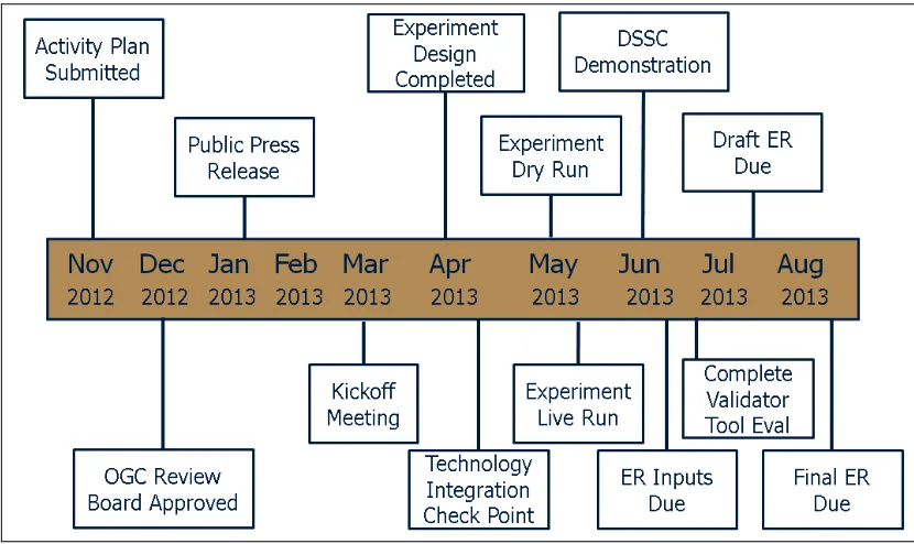
Figure 1: Detailed Execution Timeline ... 4
Figure 2: Base OWS Architecture ... 8
Figure 3: Base MOGIE Architecture ... 9
Figure 4: Land scenario data collection points ... 11
Figure 5: Maritime scenario data collection points ... 11
Figure 6: Land scenario data capture methodology ... 11
Figure 7: Maritime scenario data capture methodology ... 12
Figure 8: Data Comparison Methodology ... 13
Figure 9: MOGIE Land Scenario ... 16
Figure 10: MOGIE Land Scenario Technical Architecture ... 17
Figure 11: Maritime Terrorist Scenario ... 19
Figure 12: Maritime Scenario Technical Architecture ... 20
Figure 13: Position Report Database Attributes ... 22
Figure 14: Observation Report Database Attributes ... 22
Figure 15: Call for Fire Database Attributes ... 23
Figure 16: Latest Vessel Position Database Attributes ... 24
Figure 17: LVI and HT30 Database Attributes ... 25
Figure 18: GML PointType Definition ... 27
Figure 20 GML DirectPositionType ... 27
Figure 21 GML doubleList ... 27
Figure 21: Data Retrieval Process from WFS ... 30
Figure 22: Process to retrieve data from the WFS ... 31
Figure 23: Process of retrieving KML via WMS ... 33
Figure 24: Participant Contribution to MOGIE ... 34
Figure 25 - Envitia Exploitation Sub-system ... 35
Figure 26 – Envitia Mediating WMS Architecture ... 36
Figure 27 - Envitia Portal showing MOGIE data ... 37
Figure 28 - Envitia MapLink Pro Android Application ... 38
Figure 29: Land scenario in ArcGIS ... 38
Figure 30: Maritime scenario in FalconView ... 40
Figure 31: Playback Dialog in FalconView ... 41
Figure 32: Military and civilian vessels in the Luciad Desktop client ... 42
Figure 33: Vessel analysis and querying its historical track (shown by the white line) ... 43
Figure 34: Accessing MOGIE land scenario data and making map annotations on the Luciad Mobile client through OGC GeoPackage ... 44
Copyright © 2013 Open Geospatial Consortium
Figure 36: Source code for processing the location data ... 70
OGC
®MOGIE Engineering Report
1
Introduction
1.1 Scope
This OGC® document describes the results of the MOGIE Interoperability Experiment. This includes an
overview of the experiments, the demonstration scenarios, implemented components and workflows, and overall findings.
1.2 Document contributor contact points
All questions regarding this document should be directed to the editor or the contributors:
Name Organization
Frank W. Klucznik Georgia Tech Research Institute
1.3 Revision history
Date Release Editor Primary
clauses
The following future work items have been identified in the conduct of this study. They are intended to further development and enhancement of NIEM’s interoperability with OGC standards beyond that which exists in NIEM v3.0. Although some of these concepts may have been investigated in other OGC projects, these future work items were derived from MOGIE independent of any other OGC initiatives at the time of MOGIE execution. Whether these items are explored under MOGIE follow on work or some other OGC initiative is beyond the scope of this report.
1. Consider the value of and demonstrate that OGC OWS can output data in NIEM conformant XML. The WFS v2.0 specification, paragraph 7.6.3.7 allows an OGC WFS to provide data formats other than OGC conformant formats.
2. Consider the value of, and demonstrate how an event driven OGC OWS service delivering NIEM Compliant or NIEM derived data can complement the transactional capability of the WFS delivery used in MOGIE.
1.5 Forward
Recipients of this document are requested to submit, with their comments, notification of any relevant patent claims or other intellectual property rights of which they may be aware that might be infringed by any implementation of the standard set forth in this document, and to provide supporting documentation.
2
References
The following documents are referenced in this document. For dated references, subsequent amendments to, or revisions of, any of these publications do not apply. For undated references, the latest edition of the normative document referred to applies.
2.1 DoD data model sources NIEM: http://niem.gov
C2 Core: https://c2core.gtri.org
2.2 OGC Documents
ISO/DIS 19142 and OGC 09-025r1, OpenGIS® Web Feature Service 2.0 Interface Standard (2010-11-02)
OGC 07-036, OpenGIS® Geography Markup Language (GML) 3.2.1 Encoding Standard (2007-08-27)
OGC 06-103r4, OpenGIS® Implementation Standard for Geographic information - Simple feature access - Part 1: Common architecture, version 1.2.1 (2011-05-28)
OGC 05-134, OpenGIS® Implementation Specification for Geographic information - Simple feature access - Part 2: SQL option, version 1.1.0 (2005-11-22)
3
Terms and definitions
C2 Core Command and Control Core
IEP Information Exchange Package
IEPD Information Exchange Package Documentation
GML Geography Markup Language
MOGIE MilOps Geospatial Interoperability Experiment
NIEM National Information Exchange Model
WFS Web Feature Service
WMS Web Map Service
4
Organizations in MOGIE
4.1 Initiator Organizations
MOGIE is initiated by the following OGC members:
National Geospatial-Intelligence Agency (NGA)
MITRE
Georgia Tech Research Institute (GTRI)
4.2 Initiative Team
The MOGIE Initiative Team members are:
Initiative Manager: Frank W. Klucznik, GTRI
Initiative Technical Lead: Scott Bell, JS J6 DDC21 DSD
Initiative Facilitator: Lewis Leinenweber, OGC
4.3 Complete List of Participating Organizations
The following organizations played one or more roles in MOGIE as participants (responded to the RFQ/CFP and provided in-kind contributions).
Envitia
Esri
exactEarth
FalconView
5
Schedule
The MOGIE followed the following general schedule
Date Milestone
January 31 2013 RFQ/CFP Released
March 4, 2013 Responses due
March 20-21, 2013 Kickoff at GTRI
March – May 2013 Development, testing and bug fixing
May 2013 IE Demonstrations / Demo video / Report input
July 31, 2013 Draft Report
August 30, 2013 Final report submission
A detailed execution schedule is captured below:
6
Experiment Overview
6.1 Purpose
The purpose of the Military Operations Geospatial Interoperability Experiment (MOGIE) was to test the hypothesis proposed in the “Geolocation Accuracy and Precision in NIEM” paper that using the National Information Exchange Model1 (NIEM) v2.1 and v3.0 technical concepts does not introduce any changes in data related to accuracy and precision (Reference Appendix A).
In addition, MOGIE tested the theory that data may be read by a client without a priori access and knowledge of the data to demonstrate sharing data via OGC web services provides broader community interoperability than data shared without OGC services.
6.2 Background
This experiment came about as a result of community feedback on the Department of Defense (DoD) Command and Control (C2) Core2 in 2011. At that time, C2 Core was an emerging data exchange capability within DoD that was 93% aligned with the NIEM v2.1 Naming and Design Rules (NDR). During the evaluation and piloting of C2 Core, community members expressed concern that using the “adapter pattern” prescribed by the C2 Core v2.0 NDR would have an impact on the accuracy and precision of maritime navigation systems.
In response to these concerns, MITRE conducted a desktop analysis which concluded NIEM technical concepts would have no impact on data related to accuracy and precision. This analysis provided the basis for the “Geolocation Accuracy and Precision in NIEM” paper in Appendix A of this report. In the end, not all critics were satisfied with the results of the MITRE analysis. This provided the impetus for MOGIE to demonstrate the conclusion of the MITRE analysis was in fact valid and correct.
Two weeks after the MOGIE kickoff meeting in March 2013, the DoD CIO issued a memo announcing the decision to adopt the NIEM for standards based data exchanges. The memo also stated that future enhancements to C2 Core would not be supported, and C2 Core would form the initial content in a DoD sponsored Military Operations (MilOps) domain within NIEM. (Reference Appendix D)
Immediately after the release of the DoD CIO memo, the three MOGIE initiators all agreed to remove “C2 Core” from the experiment’s activity plan and replace it with “NIEM”. Support for this decision was in large part because the C2 Core v2.0, NIEM v2.1 and NIEM v3.0 naming and design rules pertaining to the “adapter pattern” were identical. The only condition placed on this modification was to ensure preservation of the C2 Core lineage in the background section of this report.
A complimentary effort was also conducted in the OGC Geo4NIEM3, which was led OGC members, supported by commercial vendors, and sought to:
Develop recommendations for the inclusion and standard use of embedded GML with NIEM IEPDs.
Develop recommendations for the standardized use of Naming and Design Rules and the use of adaptors (e.g. NIEM wrapper for GML) .
Test and demonstrate use of a standardized embedded GML and adaptors within NIEM IEPDs.
Develop architecture documentation and fact sheet for the use of embedded GML and adaptors for use with NIEM IEPDs.
Develop recommendations for the inclusion of a Geospatial Domain within NIEM.
1http://niem.gov
2https://c2core.gtri.org
6.3 Description
There are many commercially-available geospatial tools that exploit OGC standards. Using NIEM messages, this experiment demonstrated that GML content can be embedded in NIEM conformant XML and be exploited by commercial and open source tools without loss of precision (e.g., right number of bits) or accuracy (e.g., physical location on a map). Embedding GML in NIEM conformant XML was accomplished in MOGIE using the NIEM adapter.
There were two facets to MOGIE. The primary facet involved demonstrating the NIEM v2.1/v3.0 technical concepts work in combination with OGC’s geospatial standards (e.g., GML, WFS, WMS, etc.) in the following contexts:
NIEM conformant information exchange packages (IEPs) may contain embedded GML elements, in accordance with the GML Encoding Specification and the embedding GML best practice paper in Appendix K. This was demonstrated by embedding GML content in four different NIEM Information Exchange Package Documentations (IEPDs) and resultant IEPs. The IEPDs used in this experiment included:
Vessel Position Report developed by the NIEM Maritime Domain Awareness domain.
MOGIE Position Report loosely based on the DoD Message Text Format (USMTF) standard and Variable Message Format (VMF).
MOGIE Observation Report loosely based on the DoD Message Text Format (USMTF) standard and Variable Message Format (VMF).
MOGIE Call for Fire loosely based on the DoD Message Text Format (USMTF) standard and Variable Message Format (VMF).
The content in NIEM conformant IEPs, including embedded GML content, may be extracted and transformed into an OGC-standard format (e.g. GML, KML), and then displayed on a client through a WFS-conforming interface. Instance data was parsed and inserted into a PostGIS database. The data was then provided through a WFS-conforming interface by GeoServer and displayed on a variety of commercial and open source products including desktop client applications, browser based applications, and handheld devices.
The content from MilOps IEPs may be transformed to OGC-standard formats and/or made available through a WFS-conforming interface without loss of accuracy or precision. Data in the experiment was captured in raw form prior to transmission, and compared with the data stored in the PostGIS database after transmission, and compared with the data served up by GeoServer in WFS.
The secondary facets of MOGIE were included at the request of the DoD stakeholder community and are of equal importance. They included:
Evaluate whether use of NIEM required specialty skills. That is to say, evaluate how difficult was it for someone who had never used NIEM before to understand and utilize a NIEM IEPD. The software developer selected for MOGIE had no experience with NIEM, and had 5 years of experience developing with commodity skills such as Java, general programming, XML, databases, etc.
Use and evaluate the “GML Validator” tool currently being developed in OWS-9 as appropriate to determine compliance of GML in a MilOps exchange to GML Encoding Specifications, WFS, WMS, etc. (Reference: http://cite.opengeospatial.org/te2). This evaluation is provided in Appendix C.
Demonstrate that, if the NIEM content is modified to be GML application schema compliant delivered via OGC compliant services it can be exploited by a broad range of OGC clients which have no a-priori knowledge of the source..
Evaluate the commercial implementation and support for the latest draft of the Military Standard 2525D.4
6.4 Use cases
The primary use case for MOGIE involved transmitting data in a NIEM conformant IEP, and leveraging GeoServer to deliver the data via WFS/WMS in an OGC conformant GML application schema for display in an OGC conformant mapping tool without loss of precision or accuracy. This use case was applied in two different scenarios: land based military patrol in Jalalabad, Afghanistan, and maritime terrorist attack in San Francisco, CA harbor; both are described in detail in Section 7.
6.5 Experiments
The following experiments were addressed during MOGIE activities:
Experiment #1: Employ “GML Validator” currently being developed in OWS-9 as appropriate to determine compliance of GML in a MilOps exchange to GML Encoding Specifications, WFS, WMS, etc.
Experiment #2: Extract IEP content including geospatial data that includes GML and transform it into an OGC Standard format (e.g., WMS, WFS, etc.) with military symbology as appropriate, and then display the data on a client.
Experiment #3: Extract geospatial data that includes GML content and add additional NIEM attributes (e.g., MilOps content specified as a feature) and then display the data on a client.
Experiment #4: Demonstrate no loss of precision or accuracy when transforming GML content (e.g., location) embedded in a NIEM conformant IEP. Expose data from a NIEM conformant IEP
transformed into a GML application schema compliant form deliverable via a Web Feature Services interface and make the GML content available for vendor tools to display on a client.
Experiment #5: Demonstrate implementation of the latest draft version of MIL-STD-2525D.
6.6 Methodology and Approach
A considerable amount of time was spent on evaluating and selecting the methodology and approach used in MOGIE. The MOGIE team recognized there were a myriad of technical architectures that could be used, and all supported accomplishment of the MOGIE objectives.
To narrow down the methodology selection, the following criteria were adopted:
Simple – There was no need to make the experiment overly complex or introduce additional variables that could impact the results. The rational was a simple approach could be later scaled into a more complex architecture and would provide a basis for comparison.
Robustness – Since the two scenarios involved emergency responses (e.g., one in a war zone and the second a national terrorist attack), the design of the architecture should be sufficiently robust to support multiple simultaneous data input sources and multiple simultaneous consumer queries.
Performance - Given the two scenarios involved emergency responses, the design of the architecture should be optimized for performance.
Realistic – The scenario and architecture should align with what one might expect to see in the real world and not in a laboratory test conducted in isolation.
Given the criteria above, the overall methodology chosen was to host a GIS server in single location (e.g., GTRI in Atlanta, GA, USA) and allow the participants in Canada, the United Kingdom and Belgium to participate remotely via the public Internet. All connections to the GIS server were secured with a username/password with unsecure http.
All collaboration, including the kickoff meeting, was conducted using the OGC teleconference line in combination with the DoD Defense Connect Online desktop sharing environment.
Although the scenarios used in MOGIE were intended to portray real world situations, the technical architecture and designs were not intended to mirror or replicate existing operational systems. Any similarities or
dissimilarities to actual operational systems are purely coincidental.
6.6.1 Base Technical Architecture
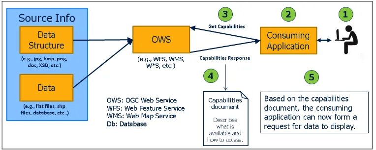
The suite of OGC standards provided a robust baseline architecture for MOGIE, and is depicted in the illustration below. The OGC Web Service (OWS), consuming application and steps 1-5 are all prescribed by OGC, implemented by commercial or open source products, and are therefore outside the scope of MOGIE. The primary focus of the MOGIE architecture is source information and how it is inserted into the OWS.
In the example of the OGC architecture provided below in Figure 2: Base OWS Architecture, the end user recognizes a need for geospatial data in step 1. In step 2, he/she uses an OGC conformant application to search and discover data to satisfy his/her need. In step 3, the application queries one or multiple preconfigured OWSs that respond in step 4 with a capabilities document. This document lists the services that are available from a particular OWS and provides request syntax. With this information, the consuming application can now request the data needed by the user and display it.
Figure 2: Base OWS Architecture
The first major architecture decision for MOGIE was to select a data source for the OWS. The data source can be provided by any source of data (e.g., steam of sensor data, flat files, relational database, etc.). Given the
PostgreSQL). This selection supported recording and playback of the scenarios for the demonstration purposes, as well as the ability to combine (e.g., mashup) commercial and simulated DoD data for the maritime scenario.
The next major decision point was to select the method for inserting NIEM conformant XML into the MOGIE database. The team evaluated two options for inserting data into the OWS. One involved using an XSLT to transform the NIEM conformant XML into WFS transaction XML. The other was to use Java code to parse the XML and populate the database with standard SQL statements. Of the two, the Java option was chosen because it could be optimized to provide better performance over an XSLT transform, and supported the evaluation of a commodity software language as a possible limitation of accuracy and precision.
It is worth noting that when using the WFS insert transaction it is possible for the NIEM conformant XML content to be inserted into a database via Java using WFS transaction. This approach was not evaluated in MOGIE. However, this approach was evaluated in Geo4NIEM.5
A third possibility was to use WFS Transactions to write the results in via the WFS interface (implemented by GeoServer). This is simply an extension of option 2 above and was not evaluated within MOGIE; however, it could be undertaken in a future experiment.
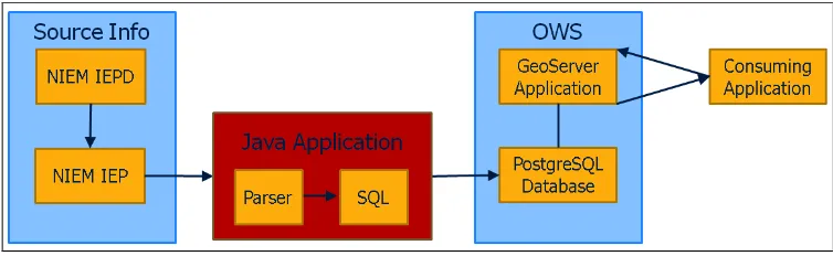
The architecture below is the result of the decision to use a relational database as a data source for the OWS, and Java code to parse the NIEM XML and insert it into the database. A more technical diagram of the land and maritime architectures is provided in Section 7 in Figure 9: MOGIE Land Scenario and Figure 11: Maritime Terrorist Scenario.
Figure 3: Base MOGIE Architecture
Note the “Java Application” in figure 3 is represented by the “MOGIE Transform Services” in Figure 9 and Figure 11.
6.6.2 Location Data Sets
Three sets of precision data for latitude and longitude were used in each iteration of the Data Collection portion of the experiment. For the purposes of this experiment, precision is measured by the number of fractional significant digits. The precisions chosen were six, ten and thirteen. For example, a longitude value 179.123456 has a precision of six and a value of 179.0123456789 has a precision of ten.
The three sets of inputs were generated from the original (e.g., raw) input data in comma separated values (CSV) format. The raw input data had longitude and latitude values with varying precisions, encoded in Well Known Text (WKT) format, i.e.: “POINT (33.7772145, -84.3961445)”. For each precision, the raw CSV coordinates were the starting point, if the precision of the raw values was greater than the target precision, the trailing digits were truncated until the precision matched. If the precision of the raw values was less than the target precision,
single random digits were generated and appended until the precision matched the target. New CSV files were then written with the corrected precisions. All other data fields were left unchanged and written in the new CSV file.
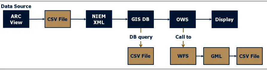
6.6.3 Data Process and Collection Methodology
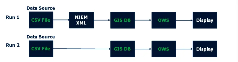
Three points for data collection were identified in the MOGIE data flow diagrams in Figure 4 and Figure 5 below. The first is the base CSV data file. The second is the PostGIS database, and the third is the output of the OWS.
Figure 4: Land scenario data collection points
Figure 5: Maritime scenario data collection points
In run #1 of both scenarios, the CSV files were parsed and written to NIEM XML instances. This process involved starting with a NIEM XML template and a CSV file. The template is an instance of the Position IEP with placeholder variables mapped to the corresponding CSV values. The CSV stores the values for the XML with field names that match the placeholder variable name. The lines of the CSV file are iterated, each line populating one XML instance. For each field in a single CSV line, the field value replaces the position of the placeholder that matches the field name.
In run #2 of both scenarios, the CSV files were parsed and data inserted directly into the PostGIS database using standard SQL insert proceedures.
Figure 7: Maritime scenario data capture methodology
Figure 6 and Figure 7 above show the process used to extract data from the previously identified data collection points. There are two points where data is extracted from storage. The first is directly exported from the PostGIS database using standard SQL queries and formatting the output into CSV. The second used standard WFS calls to get the data from the PostGIS database in a GML application format and convert that content into a CSV format.
The result of the data capture is a set of three CSV files: base data, PostGIS data, and WFS data, which was used for comparison to determine if accuracy and precision errors were introduced by the NIEM XML or the
processing of the data.
Additional details on the experiment process and data flow are included in APPENDIX B: Experiment Data Flow Description.
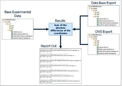
6.6.4 Data Comparison Methodology
The results of the position data comparison are provided in Appendix G, while Figure 8 provides a graphic illustration of the process.
During the position data comparison, three sets of data (e.g., P6, P10, P13) were compared from four different message constructs (e.g., position report, call for fire, observation report, vessel position report) from three data collection points (e.g., base, database, OWS) for two runs (e.g., w/ NIEM XML, w/o NIEM XML) in two scenarios (e.g., land, maritime). The data sets are described in Section 6.6.2; the data collection points are described in Section 6.6.3, a sample vessel position report instance is provided in Appendix H and I, and the scenarios are described in Section 7.
The land based position reports, call for fire and observation reports contain material subject to the U.S. International Traffic in Arms Regulations and are therefore not included in this report.
The data analysis included the following comparisons sequenced in the order presented:
1. RUN #1: Base CSV data compared to Database Export CSV of NIEM XML data
2. RUN #2: Base CSV data compared to database export CSV of directly inserted base CSV data 3. Database Export CSV compared to OWS exported GML data converted to CSV
Figure 8: Data Comparison Methodology
6.6.5 Developer Skills Required
In order to evaluate the developer skills necessary to work with and implement NIEM based XML exchanges careful consideration was given to the selection of the lead developer to support MOGIE.
The individual chosen had no prior experience with NIEM. In fact, he had not even heard of NIEM before being asked to support MOGIE. His background included:
Undergraduate degree in Computer Science
5 years software development experience; primarily Java
5 years GIS experience
1 year experience writing a WMS, WMTS and KML server for FalconView in C#
Experience working with WorldWind (Java) source code during client testing
After agreeing to work on MOGIE, the developer was provided with IEPDs and sample IEPs supporting the land scenario. Although, these artifacts were derived from previous experimentation and evaluation work with Joint Staff J6 and Esri, they still required modification to be used in MOGIE.
The developer was directed to the NIEM.gov website for technical specifications, tools, and training materials. He was also directed to the NIEM IEPD clearing house as a source for IEPDs that could support the maritime scenario.
No additional training or technical support was provided.
At the conclusion of MOGIE, the developer reported he required 4 days to review NIEM technical specifications and training before he was ready to begin working with NIEM. Although he reviewed the technical
experience.
6.6.6 MOGIE Limits of Precision
The Institute of Electrical and Electronics Engineers (IEEE) standard for Floating-Point Arithmetic (IEEE 754) is a technical standard for floating-point computation that is widely implemented and supported in computer systems and software today. The current version, IEEE 754-2008 is published in August 2008 and defines:
Arithmetic formats: sets of binary and decimal floating-point data, which consist of finite numbers (including signed zeros and subnormal numbers), infinities, and special "not a number" values
Interchange formats: encodings (bit strings) that may be used to exchange floating-point data in an efficient and compact form
Rounding rules: properties to be satisfied when rounding numbers during arithmetic and conversions
Operations: arithmetic and other operations on arithmetic formats
Exception handling: indications of exceptional conditions (such as division by zero, overflow, etc.) The standard also includes extensive recommendations for advanced exception handling, additional operations (such as trigonometric functions), expression evaluation, and for achieving reproducible results.6
In the IEEE 754 standard a single precision floating point number is stored in 32 bits and a double precision floating point number is stored in 64 bits. These bit-level storage requirements limit the preservation of floating point number precision. For example, when a string representing the MOGIE data value: 179.9999999999999 (e.g., 13 decimal precision) is parsed into a double and then printed back as a string it will yield an output of 179.9999999999999. However, when a string representing the value 179.99999999999999 (e.g., 14 decimal precision) is parsed into a double and then printed back as a string it will yield an output of 180.0. This rounding error is introduced as a result of the limitation of 64 bit storage and the numerical range of position data used in MOGIE.
A limitation feature identified in MOGIE was that the binary structure defined by IEEE 754 for storing floating point numbers does not preserve trailing zeros. For example, IEEE 754 binary cannot distinguish between 179.990000 (e.g., P6) and 179.9900000000000 (e.g., P13). IEEE 754 interprets both the P6 and P13 floating point numbers as: 179.99. The net result of this feature is that in MOGIE P6 and P10 data all trailing “0”s were omitted by software (e.g., Java, PostGIS, etc.) supporting IEEE 754. Refer to Appendix E for examples.
In response to these IEEE 754 limitations, the decision was made to prescribe precision level for MOGIE as P6, P10 and P13. In addition, trailing “0” were not replaced in the data because it did not affect the outcome of the experiment in any way.
Finally, to give readers an idea of what 13 decimal precision latitude and longitude position means in practical terms, P13 latitude and longitude precision identifies a specific location to 111,111/1013 (at the equator), or approximately 1 angstrom (e.g., the size of a chlorine atom). Although this level of precision is impossible to discern on a computer monitor, it has the potential to make a difference in some DoD targeting and tracking systems.
6.6.7 MIL-STD-2525D
At the request of the Defense Information Systems Agency (DISA) as the custodian for MIL-STD-2525, and with the approval of the Symbology Standards Management Committee (SSMC), commercial vendors participating in MOGIE were asked to use and evaluate the January 2013 draft version of MIL-STD-2525D. Both Envitia and Luciad fulfilled the request and reported no issues or recommended changes to the draft standard.7
MIL-STD-2525 provides a standardized, structured set of graphical symbols for the display of information in command and control (C2) systems and applications. As such, it represents a standard method for symbol construction using common building blocks which can be used to create current symbol sets. This includes frame, icon, modifier, and amplifier using color, graphic, and alphanumeric representations. It provides requirements for symbol construction and composition with flexibility for special user needs. This standard is approved for use by all departments and agencies of the Department of Defense (DOD) and available for use by non-DOD entities (e.g., first responders, United Nations, and multinational partners).
7
Scenario Overview
MOGIE involved two scenarios: an Amy land based scenario, and a maritime terrorist scenario. This section describes both in detail.
7.1
Land scenario
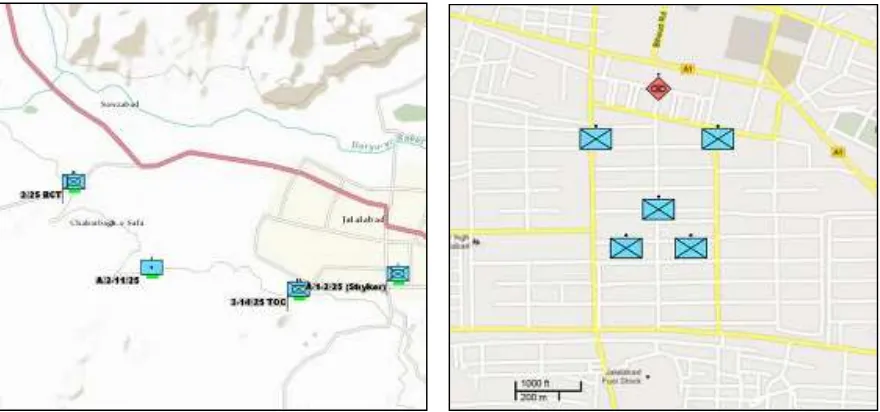
The land based scenario takes place in Jalalabad, Afghanistan and involved simulated DoD data sources.
7.1.1 Scenario Description
In the land-based scenario the 25 Infantry Division, 2nd Stryker Brigade Combat Team is set up to the west of Jalalabad. The brigade set up a field artillery battery to their east and west of the city in support of troops on patrol inside the city. A tactical operations center was also set up south of the city to improve communications with troops inside the city.
A company composed of five Infantry Squads was patrolling a section of the city beginning in the south and working northward, with two lead squads serving as scouts patrolling north of the main body of the company on the east and west boundaries of the patrol area. The remaining three squads are working up the center of the patrol area.
One of the scouts reports observing an enemy squad to the north of Alpha Company and requests fire support to destroy the enemy. A call for fire message is sent to the artillery battery and the enemy is fired upon. The scout squad observes the results of the fire and reports the enemy destroyed.
Alpha Company advances forward, verifies the kill, and continues on their patrol.
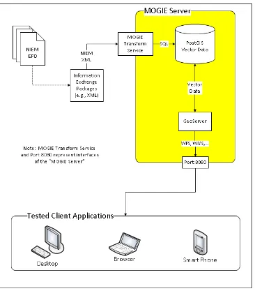
7.1.2 Technical architecture
The illustration below provides a view of the land scenario technical architecture.
NIEM IEPDs simulating military position reports, call for fire and observation reports were used to generate the NIEM conformant XML. The MOGIE Transform Service includes the XML parser and Java code written to insert the data into the PostGIS database.
GeoServer8 is an open source product that served the data in OGC conformant WFS to a desktop, browser or smart phone applications as appropriate. The WFS Transactions in this diagram were present but not used.
Figure 10: MOGIE Land Scenario Technical Architecture
Note the “MOGIE Transform Service” in Figure 10 is represented as the “Java Application” in Figure 3: Base MOGIE Architecture.
7.1.3 Data overview
Source data was produced from NIEM conformant XML based information exchanges. Three different data exchanges were used:
Position Report
Enemy Observation Report
Call For Fire
A data overview for the land-based scenario is provided in Section 8.1.
7.2
Maritime scenario
The maritime scenario involves a suspected terrorist attack in the San Francisco harbor area. Data sources include civilian vessel data as well as simulated DoD data sources.
7.2.1 Scenario Description
In the maritime scenario, a terrorist attack is reported as an explosion at a pier in San Francisco Harbor in California. Coast Guard Vessel Traffic Service (VTS) is monitoring vessels in the area via radar and AIS data. Coast Guard Pacific Area Command Center manages response to the incident and monitors vessel traffic on a common operational picture (COP) displaying public AIS data as well as data from DoD and Coast Guard vessel position reporting systems.
Figure 11: Maritime Terrorist Scenario
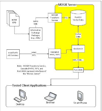
7.2.2 Technical architecture
Figure 12 provides a view of the maritime scenario technical architecture.
NIEM Maritime Domain Awareness IEPDs for vessel position reports were used to generate the NIEM conformant XML. The MOGIE Transform Service includes the XML parser and Java code written to insert the data into the PostGIS database.
Additional commercial vessel Automatic Identification System (AIS) data was provided by exactEarth in support of the maritime scenario. This data was stored in the PostGIS database through cascaded WMS and WFS and served up to clients as requested.
GeoServer9 is an open source product that served the data in OGC conformant WFS to a desktop, browser or smart phone applications as appropriate. The WFS Transactions in this diagram were present but not used.
Figure 12: Maritime Scenario Technical Architecture
Note the “MOGIE Transform Service” in Figure 12 is represented as the “Java Application” in Figure 3: Base MOGIE Architecture.
7.2.3 Data overview
8
Components
8.1 Data Source and Data Storage
This section discusses the source of the data used in MOGIE and how it was ultimately stored in the database tables. In both scenarios, the data used to support the MOGIE experiment was stored in a PostGIS enabled PostgreSQL database, which acted as the backend data source to the WFS, as shown in Figure 10 and Figure 12.
8.1.1 Land Scenario Data
Section 7.1 describes the land scenario which simulates a military use case where an enemy is spotted, targeted and destroyed. The observations and resulting attack information is collected, organized and distributed using NIEM and GML conformant XML exchanges processed through MOGIE services.
The three NIEM IEPDs used in this scenario were: Position Report Message (POSREP), Observation Report Message (OBSREP) and Call For Fire (CFF). The NIEM XML instances generated from these IEPDs were parsed with Java code and inserted in the PostGIS database using simple SQL statements. The IEPDs used in the land scenario were derived from existing IEPDs previously used in multiple venues during the development of C2 Core. For MOGIE, the IEPDs were modified in that all CUI material was removed and they were made to fully conform to NIEM v3.0 Alpha 2 release.
8.1.1.1 POSREP IEPD
The POSREP IEPD conveys the location of a reporting unit at a certain point in time. It also includes additional unit status information such as unit strength, unit identifier, unit name, etc. Additional attributes included in the database but not in the IEPD were message_time_text, time_stale, and time_stale_text. These were added to support the client development and configuration.
The time_stale attribute indicates the time when this message is no longer valid because the unit issued an updated location message. Because simulating an actual real-time data feed was outside the scope of this experiment, it was decided to playback the position reports from a pre-populated set of reports. The client developer only had to query the WFS service for the entire set and then replay them. Because the KML timespan feature was being leveraged, a start and end time was needed for each message report. For more information see Section 8.2.2.
The message_time_text and time_stale_text attributes are string type versions of the Timestamp attributes. This was necessary to facilitate the temporal field features in ArcMap. GeoServer currently has no feature that allows a timestamp format string to be passed with a WFS query. This means the WFS clients were forced to work with the default time string format. (ie: “2001-12-17T09:31:16Z”) Since this was not one of the immediatley
supported formats in ArcMap, a text version of the timestamp attributes was added with the timestamps pre-formated as a string that ArcMap understood. (ie: “2001-12-17 09:31:16”) This modification was made to all timestamp types found in both scenarios, not just Position Report Message. They are all suffixed with “_text”.
Figure 13: Position Report Database Attributes
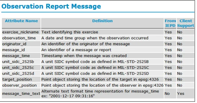
8.1.1.2 OBSREP IEPD
The OBSREP IEPD reports an observation made from a field unit. Data in this messages includes the locations and id’s of both the target and observer, as well as the time of the observation. The figure below shows the fields as they are stored in the database.
It was not necessary to add the time_stale field to the OBSREP table because this IEPD represents a single observationand not a position update as with POSREP.
Figure 14 below shows the data fields and definitions in the PostGIS database.
Figure 14: Observation Report Database Attributes
8.1.1.3 CFF IEPD
The Call For Fire IEPD conveys an order to attack. It includes information about the target, performing unit, observing unit and the message originator.
Figure 15 shows the fields as they are stored in the database.
Figure 15: Call for Fire Database Attributes
8.1.2 Maritime Scenario Data
Section 7.2 describes the maritime scenario which simulates an emergency response event in San Fracisco, CA. In the scenario, a terrorist attack is reported, and appropriate action is taken using military vessels that are in the area at the time of the event. In addition, relevant civilian vessel data was included from a commercial source to enable real time vessel tracking as well as supporting post incident investigation.
8.1.2.1 DoD Vessel Data
The basis for the simulated DoD vessel data was the Maritime Domain Awareness Vessel Information IEPD 3.2 (VEPOR) found in the public NIEM Clearinghouse.10 Supporting data was generated using Esri ArcMap v10.1.An empty point shapefile was created with the fields extracted from the IEP. The points were then manually placed on the scenario map, using the editor features in ArcMap. Finally, the vessel info, speed and heading attributes were caculated based on the vessel positions. Once the fields are all populated, the data can be extracted as a CSV file. This file was used as the input data for the experiments.
The simulated military vessels were stored in the database with the table named LatestVesselPosition. The attributes include information about the vessel’s identity, owner, current position and movement et al.
Figure 16shows the data fields and definitions in the PostGIS database.
Figure 16: Latest Vessel Position Database Attributes
8.1.2.2 Commercial Vessel Data
The source of the commercial data used in the maritime scenario was provided by exactEarth11 AIS Services through a WFS input directly into the MOGIE server. This section will describe how the data provided by exactEarth was recorded for the experiment. For more general information about exactEarth see Section 8.4.2.
MOGIE used two sources of data from exactEarth which included the: Latest Vessel Information (LVI) and Historical Track 30. (HT30) LVI is a real-time source of the vessels being tracked by exactEarth. HT30 is a 30 day track history for the tracked vessels, which supported playback of the historical movement of vessels in the area at the time of the simulated incident. exactEarth data was recorded for a window in time supporting the scenario and stored on the PostGIS database.
The LVI WFS provides the most recent positions for vessels over the entire world. To record this for MOGIE, the service was queried every minute for four hours. Each query filtered the results to the San Francisco Bay area, the exact bounding box is shown in Figure 11. The returned information was stored in the database at each request. If a location-time pair already existed for a returned vessel, that record was discarded. The end result is a four hour cache of the LVI data.
When played back, the raw LVI data had numerous ships that either did not move or moved very little over the four hour time span. This made it difficult to view the ships that did move. To deal with this, vessels were filtered to those with adequate distances between location samples. The LVI service returns the most recent location of the vessel even if it is up to 30 days old. Because this contributed to the clutter and data size, these older location samples were also thrown out.
The result was 163 unique vessels tracked from 04/13/2013 18:13:46 to 04/14/2013 06:53:25 UTC. The HT30 track for each remaining vessel was then retrieved via exactEarth’s WFS service. The 30 day tracks were to be used as an investigative tool to find out where a given vessel had been in the recent past.
Figure 17 shows LVI and HT30 data fields and definitions in the PostGIS database.
Figure 17: LVI and HT30 Database Attributes
The primary difference between the LVI and HT30 fields is the addition of from_longitude and from_latitude. These represent the previous location of the vessel. It appeared that exactEarth limits the LVI dataset to the most recent position update of each tracked vessel to improve performance. This approach allows a simple query to download the latest vessel positions for the entire planet without special filters. HT30, on the other hand, supports numerous position updates for each vessel. If the same simple query, used with LVI, were allowed with HT30 a huge amount of data would have to be packaged and transmitted to the client, seriously effecting performance on both the client and server. exactEarth forces queries to the HT30 layer to filter the results to a single vessel, using the mmsi field.
8.1.3 Data Parsing and Processing
This section explains the process used to parse the NIEM XML and insert it into the PostGIS database in both the land and maritime scenarios. During the experiment, four IEPDs were processed including the: POSREP, OBSREP, CFF and VEPOR. All four followed the same process described in this section.
8.1.3.1 Overview
Figure 3: Base MOGIE Architecture illustrates the high-level architecture to which this section will refer. The Java Application component is the custom Java source code written for the MOGIE experiment. This is also depicted in Figure 10: MOGIE Land Scenario Technical Architecture and Figure 12: Maritime Scenario
in Java version 1.6. The database was hosted using PostgreSQL12 with the PostGIS13 extension installed. PostGIS is the spatial extension to PostgreSQL. It extends PostgreSQL by adding advanced geo-spatial capabilities such as spatial query filters, multiple coordinate system support, common spatial types, etc. GeoServer is the actual server component that manages the OGC services. With a PostGIS table in place, one can use the GeoServer web interface to create, configure and manage the service that delivers the spatial data in the table.
OpenGeo version 3.0.2 was used to install and configure GeoServer, PostGIS, PostgreSQL and the various dependencies included in the OpenGeo stack.14 Referencing Figure 3, all interaction between the Parser and SQL components, that is, all interaction between the MOGIE Java application and the database used the official JDBC4 version 9.2-1001 driver provided by PostgreSQL.15
8.1.3.2 XML Parsing
The conversion from XML to the database was a standard process of parsing the XML to extract the data and then constructing SQL statements to insert that data into the database. The standard Java DOM parser was used to parse the xml. The elements of each IEP were mapped to the column names in the database.
The initial input is a NIEM XML instance, an example of one for VEPOR is provided in appendix H. The part most relevant to this section is the GML Point element:
<gml:Point srsName="http://metadata.ces.mil/mdr/ns/GISP/crs/WGS84E_2D">
<gml:pos>37.1498819680237 ‐123.5583574667275</gml:pos>
</gml:Point>
The above GML Point has two pieces of important information, the srsName attribute and the gml:pos element. The srsName attribute indicates the coordinate system used for the coordinate values. Among other things, the coordinate system defines the units and axis ordering for the coordinates. In this case, the referenced system uses angular units, latitude and longitude, with latitude first. The gml:pos element holds the actual coordinates as a GML doubleList type. (GML3.2.1, Section 10.1.4.1)
GML Data Types
Because the conversion of the actual values from one type to another is the true source of any loss of data, here the GML Point type definition is discussed.
GML PointType is defined in OGC 07-036 (GML3.2.1) Section 10.3.1. The section states:
A gml:Point is defined by a single coordinate tuple. The direct position of a point is specified by the gml:pos element which is of type gml:DirectPositionType.
gml:Point implements ISO 19107 GM_Point (see D.2.3.3 and ISO 19107:2003, 6.3.11).
The use of the element “coordinates” is deprecated. Use “pos” instead.
<complexType name="PointType">
<complexContent>
<extension base="gml:AbstractGeometricPrimitiveType">
<sequence>
<choice>
<element ref="gml:pos" />
<element ref="gml:coordinates" />
</choice>
substitutionGroup="gml:AbstractGeometricPrimitive" />
Figure 18: GML PointType Definition
Figure 19 shows the defining XML. From here, the choice of how to actually store the coordinate values comes down to gml:pos or gml:coordinates, but as stated by the standard, gml:coordinates is deprecated so the gml:pos element will actually hold the values.
GML DirectPositionType (gml:pos) is defined in Section 10.1.4.1 of GML3.2.1. Figure 19 shows the defining XML, and indicates that the values will be stored as a gml:doubleList.
GML doubleList is defined in Section 8.2.4.1 of GML3.2.1. Figure 20 shows the defining XML. The sections states:
NOTE 3 An element which uses one of these types will contain a whitespace-separated list of members of the relevant type
(see http://www.w3.org/TR/xmlschema-2/#atomic-vs-list for more details of the XML list structure).
XML double is defined in XML Schema Part 2: Datatypes Second Edition16 Section 3.2.5. The section states:
[Definition:] The double datatype is patterned after the IEEE double-precision 64-bit floating point type [IEEE 754-1985]. The basic ·value space· of double consists of the values m × 2^e, where m is an integer whose absolute value is less than 2^53, and e is an integer between -1075 and 970, inclusive…
16 http://www.w3.org/TR/xmlschema-2/#double
Figure 20 GML doubleList Figure 19 GML DirectPositionType <complexType name="DirectPositionType"> <simpleContent>
<extension base="gml:doubleList">
<attributeGroup ref="gml:SRSReferenceGroup"/> </extension>
</simpleContent> </complexType>
<element name="pos" type="gml:DirectPositionType"/>
…Leading and trailing zeroes are prohibited subject to the following: number representations must be normalized such that there is a single digit which is non-zero to the left of the decimal point and at least a single digit to the right of the decimal point unless the value being represented is zero. The canonical representation for zero is 0.0E0.
The following section discusses the next step which is to parse the text representation of the coordinates, convert them into IEEE 754 doubles and insert them into the database.
8.1.3.3 Database Insertion
The standard PostgreSQL JDBC driver was used to populate the database from within Java. This step is where the longitude and latitude are converted to doubles in Java and then to a Point type in the database. This section will follow a high level discussion of this process, for a detailed example of the process including source code see appendix J.
Essentially, the input to the database insertion code is a string with a latitude followed by a longitude. From the GML Point definition, it is assured that this string should be two valid IEEE 754 doubles with a single space between them. The single string can now be split into two separate strings, without the space, by calling the String.split(“ “) function. Each of these can then be converted to Java doubles with the function
Double.valueOf(String).17 Now the coordinates are actually stored as IEEE 754 doubles in memory.
Next the doubles must be prepared to be inserted into the PostGIS database. PostGIS will store the coordinates as a Point object, or column, in the spatially enabled database table. To achieve this, the coordinates will first be converted to Well Known Text (WKT) format and then passed into the SQL function
ST_GeomFromText(WKT,EPSG), provided by the PostGIS extension. The ST_GeomFromText function converts a WKT representation of an OGC Point, into the internal binary structure. Again, detailed steps are shown in annex J. It’s worth noting here that there are obviously multiple ways to insert GML into a PostGIS database. This approach was chosen to make the actual coordinate conversion process as explicit and visible as possible. Also, while it is not necessary to convert the coordinate values from text into doubles for this simple example, common use-cases might require including this conversion for error-checking, pre-processing, additional calculations on the coordinates before inserting them into the database.
Once the data is in the database, GeoServer takes the conversion from there. However, reading from the database is not overly complicated. This can be accomplished with PostGIS functions. For example,
ST_AsText(geometry_column) will return the value of a spatial column as WKT. To ensure the returned value has not lost precision, a more direct function is ST_AsBinary(geometry_column) which will return the Point as Well Known Binary. (WKB) WKB encodes the actual coordinate values as binary IEEE 754 doubles.
Data Types
The Java double is explained in the Java Language Specification Section 4.2.3. (http://docs.oracle.com/javase/specs/jls/se7/html/jls-4.html#jls-4.2.3) The section states:
The floating-point types are float and double, which are conceptually associated with the single-precision 32-bit and double-precision 64-bit format IEEE 754 values and operations as specified in IEEE Standard for Binary Floating-Point Arithmetic, ANSI/IEEE Standard 754-1985.
Point is defined in OGC 06-103r4 Simple Feature Access - Part 1: Common Architecture (SFA-CA) Section 6.1.4.
Well Known Text (WKT) is defined in SFA-CA Section 7. An example can be viewed in annex J.
Well Known Binary (WKB) is defined in SFA-CA Section 8. The section states:
The Well-known Binary Representation for Geometry is obtained by serializing a geometric object as a sequence of numeric types drawn from the set {Unsigned Integer, Double} and then serializing each numeric type as a sequence of bytes using one of two well defined, standard, binary representations for numeric types (NDR, XDR)…
… A Double is a 64-bit (8-byte) double precision datatype that encodes a double precision number using the IEEE754 double precision format.
The above definitions are common to both XDR and NDR.
More information on the functions ST_GeomFromText, ST_AsText and ST_AsBinary can be found in OGC 05-134 Simple feature access - Part 2: SQL option (SFA-SQL) and ISO/IEC CD 13249-3:2006(E) – Text for FDIS Ballot Information technology – Database languages – SQL Multimedia and Application Packages — Part 3: Spatial, May 15, 2006. (SQL/MM)
8.2 Data Delivery Services
The two primary outputs used in MOGIE were GML via WFS and KML via WMS. This section explains the interaction between the client and server for both output types.
8.2.1 WFS and GML
WFS has many components and supports multiple formats. It is outside the scope of this document to thoroughly describe them all. Therefore, this section describes the components of WFS used by MOGIE and the resulting GML output.
As with all OWS compliant services, there is an initial negotiation phase that begins with the client application requesting a capabilities document. While the structure of these XML documents varies from service to service, their general function is the same, they provide the client with the necessary knowledge to query the services provided. Figure 21 illustrates this process.
The first arrow shows the client issuing a GetCapabilities request to the server. This initial request typically takes the form of a HTTP GET call. This is the type of call made by a web browser when a URL is entered into the browser address bar. To construct the GetCapabilities request, one starts with a base address, in the case of MOGIE: http://falconservices.icl.gtri.org:8080/geoserver/ows?. The question mark at the end indicates the beginning of parameters to follow. The two required parameters, in this case, are service and request. Setting service=WFS and request=GetCapabilities tells the server to return the capabilities XML document for its WFS service. The final request URL looks like this: http://falconservices.icl.gtri.org:8080/geoserver/ows?service=WFS&request=GetCapabilities.
The second arrow shows the server responding with the capabilities document. This document can be quite complex, depending on the server’s capabilities. The figure shows parts we will focus on for the purposes of MOGIE.
o The first and second elements shown, collapsed, are GetFeature and DescribeFeatureType Operations. They will be discussed later but generally tell the client how to actually make those requests.
o The third element shown, expanded, is the FeatureType of interest, latest_vessel_position. This tells the client only basic information about the feature, including its name, prefixed with its namespace, and the geographic bounding box to which the spatial data is constrained. Now the client has enough information to query the service further, as shown next.
The final arrow shows the server responding with the GML application schema of
latest_vessel_position. The client now knows exactly what to expect when it actually receives the requested data. (Note: part of the XML is collapsed to save space) The information contained here includes the field names and types, which will be used, among other things, for filtering the data in subsequent requests. The schema itself can also be used to validate the actual Features when retrieved.
Figure 21: Data Retrieval Process from WFS
Figure 22 shows the process to retrieve the actual data from the WFS.
The first arrow shows the client issuing a GetFeature request for the latest_vessel_position GML data. This is the simplest form of the GetFeature request. A more complex GetFeature request could include spatial, temporal, numeric, etc. filters to limit the returned data.
The second arrow shows the server responding with the GML Feature data. It should be noted,
Figure 22: Process to retrieve data from the WFS
The basic process of discovering and retrieving data via WFS has been shown. However, WFS has many capabilities, some of which were enabled but not used in the end. For example, data can be inserted, modified and deleted all with WFS operations similar to those shown above. The developer tested these operations, initially, in case they found a use as the experiment evolved. While they did not, it should be noted to GeoServer’s credit, that they did function correctly.
8.2.2 WMS and KML
MOGIE also supported the use of KML (formerly known as Keyhole Markup Language) as an output format. Originally designed for Google Earth, KML 2.2 was adopted as an OGC standard in 2008. Essentially, KML is capable of embedding vector data and styling instructions in the same XML document. GeoServer uses WMS to deliver KML, which allows the client to specify which style they would like embedded in the KML document. As with WFS, both WMS and KML can become quite complex. This section only focuses on the very basic use of both, as they were used by MOGIE.
Figure 23 illustrates the process of retrieving KML via WMS, as supported by GeoServer.
The first arrow shows the familiar GetCapabilities request from the client.
The second arrow shows the server responding with the WMS capabilities document. Here, only the two important parts of the document are shown.