A Cable-less Interaction Device for AR and VR Environments
H. T. Regenbrechta, G. Baratoffa, I. Poupyrevb, and M. Billinghurstc
a
DaimlerChrysler Research and Technology Ulm / Germany
b
ATR MIC Lab, Kyoto / Japan
c
HITL, University of Washington, Seattle / WA / USA
a
{Holger.Regenbrecht|Gregory.Baratoff}@DaimlerChrysler.Com, [email protected], [email protected]
Abstract
This paper describes the Magic Pen, a modified pen that allows natural cable-less interaction with AR environments. The pen is a normal pen with bright Light Emitting Diodes (LEDs) mounted at each end. Using computer vision techniques, these LEDs are tracked in the image captured by a head-mounted camera, and the pen’s position and orientation are computed. This permits the use of image plane interaction techniques for interacting with virtual images. We describe the computer vision algorithms used, the tracking results and the interaction supported.
Keywords: Augmented Reality, Interaction Techniques, Wearability, Virtual Reality
1 Introduction
In this short paper we describe the Magic Pen – a new input device that can be used for natural cable-less interaction within an AR interface. Two of the most basic interaction tasks have been addressed: virtual object selection and manipulation.
In many AR systems computer vision techniques are used to track user position and orientation, or to provide visual input for video see-through systems. Taking advantage of this we have developed the Magic Pen interface, where a real pen with Light Emitting Diodes (LEDs) mounted on it is tracked by a head mounted camera. The goal is to have an intuitive to use 5 degree of freedom (DOF) input device where the object affordances suggest how the object is to be used and match the requirements of the task.
The current prototype of the Magic Pen (version 2.0) incorporates LEDs into an actual physical pen (figure 1). We have mounted one LED at each end of the pen along with switches on the pen body. Two AA batteries to power the LEDs are concealed inside the pen shell. The LEDs are turned on with a push button switch at the end of the pen. The pen is used in an AR setup in combination with a Sony Glasstron HMD and a Toshiba mini camera connected to an SGI Visual Workstation 540 running Windows NT.
The LEDs are tracked in the camera image using fairly simple image processing algorithms. The length of the pen is fixed, and by determining the center and region size of the LEDs projection in the camera image, we can find the 3D coordinates of the end points of the pen and
hence a ray vector through these end points. Thus the Magic Pen can be used either for direct pointing with the tip of the pen (3DOF) or for raycast interaction using several LED’s (5DOF). In either case the interaction is cable-less and intuitive.
We have explored two approaches for Magic Pen tracking: The IR-LED method, where the LEDs are mounted on the pen are Infra-Red, and the Color-LED approach with color LEDs. Because the latter is the more promising approach, we now use it exclusively.
2 Algorithm
The prototype setup runs within an OpenInventor framework in combination with a marker based tracking approach given by ARToolKit [Billinghurst 1999].
While OpenInventor provides some essential functionality in displaying VR geometry, ARToolKit allows a fairly exact and robust tracking of the whole scene. The Magic Pen code is added to provide the necessary interaction functionality needed within the scenario.
The process of obtaining 5DOF information from the two LED driven Magic Pen can be divided into five main steps:
The video buffer capture is done using SGI's Media SDK, which provides full size video images (PAL or NTSC) with an update rate of more than 20 frames per second in 24 bit color mode. This video signal is then used to display the real world images on the backplane of the render context as well as for marker and Magic Pen detection.
In a color labeling step the whole image is searched for the colors of the pen LEDs (in our case yellow and red). For each pixel the label (front LED, back LED, background) is determined by indexing (using the pixel color) into a 3D lookup table. Each entry of this array is initialized to the label of the LED whose color is closest to the pixel’s color, provided that the distance falls below a fixed threshold. If the distance threshold is exceeded, the pixel is labeled as belonging to the background. The result of this step is a label image the same size as the original image, with each pixel indicating whether it is a background pixel or which LED it belongs to.
of interest (yellow or red color respectively). We use the CCC method (“Color Connected Components” [Baur, 2000], based on the multi-value connected component method described in [Mandler, 1990]). CCC extracts all regions with 4 or more connected pixels of the same color. Since LED image regions can be fragmented (appearing as several connected components), we introduce a spatial merging step which combines several proximal regions into one. Further variability in region size and position can be reduced by accumulating the region estimates over time using a moving average filter. In the depth coordinate estimation step, the Z coordinate of each LED is computed from its image region size and position. The computation relies on the known size of the LEDs, and accounts for the effects of perspective foreshortening and image position eccentricity.
In the final 5DOF computing step, the coordinates of the line in space connecting the tip and the back LED are computed from their 3D positions. This 5DOF value is used to implement a raycast device in our application, as shown in Figure 1.
Figure 1 Screenshot of virtual ray cast.
Results
Our current implementation of the Color-LED tracking is slower than the IR-LED approach, achieving only a few frames per second. This is enough to show the practicality of the approach in principle, but is not sufficient for interactive use. We have identified the (currently not optimized) region finding step as the major performance bottleneck, and are currently concentrating our efforts on the optimization of this component in order to enable higher interactivity for our application scenario.
3 Application scenario : Design of
Instrument Panels
Although our techniques are broadly applicable, our specific application area is the design of aircraft instrument panels, a joint research initiative carried out
with support from DASA/EADS Airbus (see also [Poupyrev, 2000]).
In our interface, we allow designers, engineers, human factors specialists, and aircraft pilots to quickly layout and rearrange a set of virtual aircraft instruments on a board simulating an airplane cockpit.
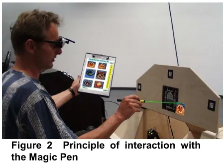
Figure 2 Principle of interaction with the Magic Pen
Figure 2 shows a snapshot of a user in the process of designing the cockpit layout. Using the Magic Pen, the user selects the virtual aircraft elements from a catalog (attached to a clipboard held in his left hand) and positions them on the dashboard of the mockup.
4 Acknowledgements
We want to thank all members of the Virtual Reality Competence Center, the ATR MIC Lab, and the HITLab for their contributions. We furthermore want to thank Thore Schmidt-Tjarksen (“640x480”, Weimar, Germany) for our discussions and prototype setups.
5 References
[Baur, 2000] Baur, H. Eine schnelle ANSI-Implementierung des CCC-Verfahrens zur topologischen und geometrischen Bildanalyse [ANSI implementation of CCC procedure for topologic and geometric picture analysis], DaimlerChrysler Research and Technology F3M/B, 2000.
[Billinghurst, 1999] Billinghurst, M., Kato., H. Real world teleconferencing. In Proceedings of CHI’99 Abstracts and Applications. 1999
[Mandler, 1990] Mandler, E., Oberländer, M. One-pass Encoding of Connected Components in Multi-Valued Images, 10th ICPR, Atlantic City, New Jersey, 1990.