Removal Efficiency of Nitrite and Sulfide Pollutants by Electrochemical Process
by Using Ti/RuIrO
2Anode
Aris Mukimin
*and Agus Purwanto
Center of Industrial Pollution Prevention Technology,
Jl. Ki Mangunsarkoro No. 6 PO Box 829, Semarang 50136, Indonesia
Received July 17, 2017; Accepted December 18, 2017
ABSTRACT
In general, wastewater treatment by physical, chemical and biological methods are only focused on TSS, BOD and COD removals that the effluent still contains anion pollutant as NO2- and S2-. Electrochemical technology is a
proper method for those pollutants treatment due to its fast process, easy operation and minimum amount of sludge. Electrocatalytic reactor with 8 L capacity using Ti/RuIrO2cylinder as anode and Fe plate as cathode was arranged
and applied to treat anion pollutants. Hydraulic retention time (30, 60, 90, and 120 min), salt concentration (250, 500, and 750 mg/L) and voltage (4, 5, and 6 V) were chosen as operation variables and NO2- and S2-concentrations as
parameter indicators. Nitrite removal efficiency reached 75 and 99.7% after 60 and 120 min of electrolysis, respectively, while sulfide could obtain higher efficiency, i.e., 97 and 99.9% after 60 and 90 min, respectively, at operation variables of potential of 5 V and salt of 500 mg/L. Removal process is dominated by indirect oxidation mechanism by HClO/ClO-oxidators generated at anode surface as intermediate products. The lifespan of electrode
and electric consumption are two main factors of operation cost. Electric consumed was 0.452 kWh per 1 g nitrite removed.
Keywords:sulfide; nitrite; electrochemical; Ti/RuIrO2anode; Fe cathode
ABSTRAK
Pengolahan air limbah industri secara fisika, kimia dan biologi umumnya hanya memfokuskan pada penurunan konsentrasi TSS, BOD dan COD sehingga effluentnya masih potensial mengandung polutan anion seperti NO2-dan
S2-. Pengolahan berbasis elektrokimia merupakan metode yang tepat untuk mereduksi polutan tersebut karena
berlangsung secara cepat, mudah dan tanpa sludge. Reaktor elektrokatalitik 8 L dengan silinder Ti/RuIrO2sebagai
anoda dan plat Fe sebagai katoda telah disusun kemudian digunakan untuk mengolah air limbah anion. Waktu tinggal (30, 60 dan 90 menit), konsentrasi garam (250, 500, 750 mg/L) dan voltase (4, 5, 6 V) dipilih sebagai variabel operasi dengan NO2-dan S2-sebagai parameter indikator. Efisiensi reduksi nitrit dapat mencapai 75% dalam waktu
60 menit dan 99,7% (120 menit), sedangkan sulfida diperoleh penurunan lebih tinggi yaitu 97% selama 60 menit dan 99,9% (90 menit) dengan kondisi operasi tegangan terpasang 5 V dan penambahan garam 500 mg/L. Penurunan ini dominan berlangsung dengan mekanisme indirect oxidation melalui pembentukan oksidator HClO/ClO- sebagai
intermediated reaksi. Umur pakai elektroda dan kebutuhan listrik menjadi faktor utama biaya operasional dengan konversi kuantitas penurunan 1 g nitrit terhadap konsumsi energi sebesar 0,452 kWh.
Kata Kunci:sulfida; nitrit; elektrokimia; anoda Ti/RuIrO2; katoda Fe INTRODUCTION
Many industries, e.g., textile, tannery, food processing, pulp and paper, rubber latex, explosive manufacturing, and pesticides, discharge nitrogen-rich wastewater [1] that may generate nitrite when treated by biological treatment [2]. Particularly, chemical and petrochemical wastewater may contain nitrite due to the process of generating "sour water" [3]. Sulfide may be detected in industrial wastewater discharged by petroleum refineries, tanneries, and food processing plants, among others [4]. Ortiz et al. [1] reported that all
NH4+ was oxidized to nitrate when S2- concentration was 3.1 mg/L, while in a higher concentration (6.4–13.5 mg/L) the removal efficiency of NH4+ is low and may cause nitrate accumulation.
Nitrite is potentially hazardous to human health and may cause severe problems to aquatic ecosystem [5]. Anion nitrite contained in drinking water will pose a higher risk of pancreatic cancer to human [6]. Nitrite has been approved as the main source in N2O production. This compound is one of greenhouse gases that may inflict not only serious environmental damage but also cause ozone layers depletion. On the
other hand, in practice, sulfide is typically removed from wastewater by aeration or chemical oxidation. During aeration, free sulfide in the form of H2S is generally carried along with air to the atmosphere to the extent of 0.04 mg/L, thus the surrounding aerial environment is often dominated by H2S. It may explain why plant operator and people surrounding treatment plant frequently complain of having headache and feeling nauseous. Diffusion of absorbed H2S in blood plasma to bones, spleen, lungs, liver, kidneys, pancreas and small intestine has also been reported [7]. While sulfide is corrosive and may cause pipe fouling due to deposition [8].
Biological treatment is generally used as a common method to remove nitrogen and sulfur from wastewater. It can be conducted by two-coupled respiratory process, aerobic and anaerobic [9]. Denitrification is a suitable technology involving four enzymatic steps in which nitrate is reduced to nitrite, nitric oxide, nitrous oxide and finally N2[2]. While sulfide-oxidizing bacteria was proven to be efficient in removing sulfide from wastewater [10]. However, aside from its long process, denitrification have several weaknesses, such as release of nitrite due to (1) nitrite production (accumulation) in wastewater treatment through partial oxidation of ammonia via nitrification, (2) nitrite accumulation during biological denitrification process when the electron donor is stoichiometrically insufficient or when nitrate reduction process is faster than nitrite reduction [11-14]. Previous studies have reported the formation of N2O in the process of nitrogen removal in biological wastewater treatment. The rate of N2O emission varies greatly, depending on the quality of wastewater and the operating parameters [15].
Electrochemical treatment of several pollutants achieves high removal efficiency, produces no sludge, occupies small area and requires relatively low investment cost. Electrode is the main material which determines the efficiency of degradation. Metal oxide such as RuIrO2 is an active and powerful anode for degrading pollutants [16]. Several studies have indicated that RuIrO2 is capable of generating OH° and more active in the presence of chloride ion due to the promotion of chlorine-mediated electrolysis. In the presence of Cl- ion, indirect oxidation of contaminants via Cl2/HClO/ClO- will be promoted. HClO and ClO- is a long live oxidant which is able to diffuse away into the bulk liquid and react chemically with contaminants [17].
In general, application of electrochemical process for denitrification is limited due to generation of ammonia and nitrite. Vanlangendonck et al. [18] reported that chloride ion present in solution will be oxidized to chlorine at the anode and immediately reacts with water to form hypochlorite, which will react with ammonia during electrolysis. On the other hand, if nitrite was
present, it will be oxidized by hypochlorite to form nitrate. Nitrate would be reduced to ammonium with zero-valent iron [19]. The reaction can be expressed as follows:
NO3-+ 10H++ 8e-⇌NH4++ 3H2O (1)
4Fe⇌4Fe2++ 8e- (2)
Li et al. [20] mentioned that nitrate will be reduced to nitrogen with ammonium as by-products. The reduction is conducted electrochemically and the highest result was obtained with Fe as cathode.
Sulfide can be removed by oxidation process without producing metallic sludge [21]. The oxidation of this pollutants may be promoted by the presence of salt. Wang et al. [22] reported sulfide removal due to production of hypochlorite oxidation formed at the anode according to following two stages: first, ClO-will oxidize HS- into elemental sulfur (S°) and further oxidized into sulfate, while the second process is faster than the precipitation of sulfur thus SO42- will be the major product of electrolysis.
The aim of this work is to remove nitrite and sulfide using an electrochemical cell. The reactor was constructed as an undivided cell using cylinder Ti/RuIrO2 as anode and Fe as cathode. The effect of chloride ion and voltage applied were investigated towards high removal efficiency. The composing element and surface morphology of anode and were analyzed to determine the stability of electrode. The energy consumption was evaluated to find the optimum operating condition.
EXPERIMENTAL SECTION
Materials
Synthetic nitrite and sulfide solutions were prepared using NaNO2 (Merck) and Na2S (Merck). Chemical reagents were used to measure NO2- by referring to APHA-AWWA Analysis Methods (4500 NO2-B) using Gallery Instrument (Thermo Scientific). The measurement of S2- concentration was conducted using the International standard method (APHA-AWWA 4500-S2-D) and all reagents used were of analytical grade (Merck). Ti/RuIrO2electrode was purchased from Baoji Changli Special Metal Co., Ltd. The SEM and EDX (JEOLJSM-6360LA and PHENOM PRO-X DESKTOP) data were provided to investigate surface morphology and composing element of anode.
Instrumentation
Electrocatalytic reactor tube of 8 L capacity was constructed using polyvinyl chloride (PVC). Ti/RuIrO2 electrode (ø:50 mm x h:800 mm) as anode was paired
cathode in the center of the tube. The reactor was then placed was on a magnetic stirrer and the electrode was connected to DC power supply (GW INSTEK SPS-1230). Visual configuration of tube reactor is depicted in Fig. 1.
Procedure
The initial nitrite and sulfide concentrations of synthetic wastewater were 3.87 and 5.53 mg/L, respectively. The wastewater was prepared by dissolving 1.8576 g of NaNO2 and 1.2324 g of Na2S (35%) with distilled water to the total volume of 32 L. Two grams of salt was added to 8 L of synthetic wastewater and then stirred to complete as it dissolves perfectly.
The synthetic wastewater was then fed into electrocatalytic tube reactor for electrochemical process. Power supply was then used to apply potential at 5 V. The treated wastewater samples were collected continuously from reactor after 30, 60, 90 and 120 min and analyzed for nitrite and sulfide concentrations.
The same procedure was done for the other operating parameter i.e., salt concentration (500 and 750 mg/L). The optimal voltage parameter was investigated according to the same procedure at salt concentration of 500 mg/L and potential of 4 and 6 V.
RESULT AND DISCUSSION
Removal of Nitrite
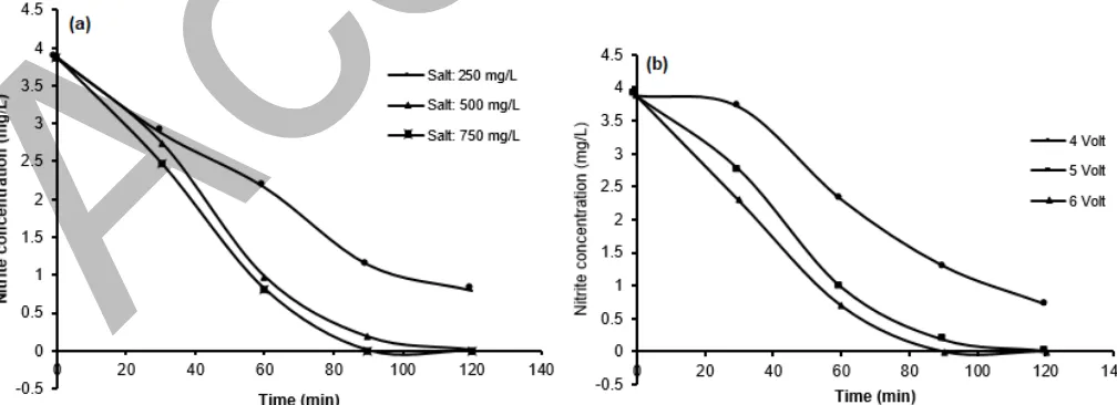
Fig. 2a shows removal of nitrite during electrolysis process on varied salt concentration. At salt concentration of 250 mg/L, nitrite was decreased from 3.87 to 2 mg/L in 60 min and then to 0.8 mg/L in 120 min
and more with a higher amount of salts (500 mg/L). At this condition, nitrite removal reached 0.98 mg/L after 60 min and 0.01 mg/L after 120 min. This phenomenon might be due to the oxidation reaction of nitrite with hypochlorite acid (HClO) generated at anode. Cheng and Kelsall [23], Martinez-Huitle and Brillas [24] and Mukimin et al. [25-26] have reported the formation of hypochlorite from chloride ion by metal oxide electrode through following mechanisms:
2Cl- → Cl
2+ 2e- (3)
Cl2+ H2O → HClO + H++ Cl- (4)
HClO → ClO-+ H+ (5)
A higher amount of salt accordingly will increase
Fig 1. Electrocatalytic tube reactor consists of (1) magnetic stirrer, (2) PVC tube, (3) Ti/RuIrO2 cylindrical anode, (4) Fe cathode and (5) DC power supply
Fig 2.Nitrite removal in electrochemical process (a) at varied concentration of salt and (b) at varied applied voltage at 500 mg/L of salt
Fig 3.Sulfide removal in electrochemical process (a) at varied salt concentration and (b) varied voltage at 500 mg/L of salt
hypochlorite formed. Li et al. [20] mentioned that nitrite was easily oxidized by hypochlorite acid to form nitrate. The equation for this reaction is as follows:
NO2-+ HClO → NO3-+ H2O + Cl- (6) Meanwhile, nitrate anion formed is effectively reduced to ammonium by iron cathode [19] by the following reaction:
NO3-+ 10 H+ + 8e-⇌NH4++ 3H2O (7) Ammonium formed is also easily reduced by hypochlorous acid to nitrogen [20]. The equation of the reaction is as follows:
NH4+ + HClO → N2+ H2O + H++ Cl- (8)
Nitrite removal rate was steadily increased with the addition of salt at 750 mg/L, where nitrite was decreased to 0.82 mg/L after 60 min of electrolysis. It was probably due to the higher hypochlorous acid production leading to accelerated oxidation of nitrite. Optimum removal (the limited detection of nitrite measurement) of 0.01 mg/L was achieved with a shorter time of about 90 min. A different trend was observed when salt was added at 500 mg/L, where optimum removal was achieved after electrolysis of 120 min.
The nitrite removal rate is also influenced by voltage. At an applied potential of 4 V, nitrite concentration was decreased to 2 and 0.71 mg/L after electrolysis time of 60 and 120 min, respectively. A higher removal was observed at applied potential of 6 V, i.e., 0.7 and 0.01 mg/L after 60 and 120 min. While, at applied potential of 6 V, the optimum removal was achieved after electrolysis time of 90 min. This increasing trend is probably due to (1) effect of potential towards formation of hypochlorous acid, (2) direct reduction of nitrite to ammonia by Fe cathode. Hypochlorite formation and direct reduction indicators may easily be detected based on the current response (0.9 A at 4 V and 1.7 A at 6 V).
The electrochemically reduction of nitrite to ammonia has been reported by Alowitz and Schere [27]; Uyeda and Peter [28]. This process requires a high pressure or high overpotential. Winther-Jensen [29] reported a reduction nitrite to ammonia at low potential i.e. -0.5 V vs Ag/AgCl by Fe-complex cathode. They explained that the reduction occurs through the formation of iron-nitrosyl complex (Fe (II)(NO+)). At pH range of 2–8, NO2-will be converted to HNO2, which will subsequently react with Fe(II)(H2O) to form Fe(II)(NO+) complex. This complex will be furtherly reduced to NH3 or NH4+. The overall electrochemical reaction of nitrite to ammonia needs 6 electrons according to following equation:
NO2-+ 7H+ + 6e → NH3+ 2H2O (9)
Removal of Sulfide
Fig. 3 shows a decreasing trend of sulfide during electrolysis. Sulfide removal was observed at a short period of time, i.e., 1.06, 0.24, and 0.002 mg/L after 30, 60, and 90 min of electrolysis time, respectively, with an initial concentration of 5.53 mg/L. Sulfide removal by electrolysis is possible through two pathways, i.e. direct oxidation of S deposit to anode surface or by the formation of sulfate. Sulfide removal by deposition process can be evaluated by EDX measurement of anode surface. Fig. 6 shows no increasing content of sulfur element which indicates that anodic deposition process did not occur. Based on this result, sulfide removal was possibly due to the oxidation of sulfide into sulfate. This phenomenon was previously reported by Wang et al. [22]. They added BaCl2 solution to processed wastewater and precipitation was observed which is a strong indicator of BaSO4formation.
Fig 4.Trend of pH vs time at (a) varied salt concentration and (b) applied voltage
Fig 5.SEM images of anode surface (a) before and (b) after application
Sulfide removal via oxidation process was also indicated by the changes of solution acidity. Fig. 4 shows that pH was declined during electrolysis process in reactor. The initial pH of 8.5 was decreased to 7.7 and 7.3 after 60 and 120 min, respectively. This phenomenon was observed with the addition of salt on varied applied voltage.
The addition of salt to the electrolysis process may affect sulfide oxidation rate into sulfate. Chloride, which is readily oxidized to hypochlorite acid by Ti/RuIrO2 anode, will react with sulfide to form sulfate. Wang et al. [22] previously explained sulfide reactions with hypochlorite via following mechanisms:
ClO-+ HS- → Cl-+ S + OH- (10) S + 3ClO-+ 2OH- → SO
42-+ 3Cl-+H2O (11) Fig. 3a shows sulfide decreasing rate at varying salt concentrations. Based on this result, it is clear that salt concentration did not significantly affect sulfide removal and tend to be constant after 500 mg/L. It was possible due to the insufficient initial concentration of
sulfide and rapid oxidation of sulfide, especially via direct mechanism at the anode.
In addition to salt, the effect of voltage towards sulfide removal was also investigated. Fig. 3b shows declining concentration of sulfide at applied voltage of 4, 5, and 6 V. Increased voltage applied to reactor would moderately accelerate sulfide removal. This is possibly due to the high rate of sulfide oxidation via indirect mechanism on anode at applied potential of about 4 V. Increasing applied potential (5 or 6 V) would likely increase the oxidation of H2O to O2 as indicated by the increasing oxygen bubbles formed at the anode.
Electrode Stability
Electrode stability is a prominent factor affecting its application in wastewater treatment. Fig. 5 shows the surface image comparison of Ti/RuIrO2 anode before and after electrolysis process. Anode surface appeared to undergo changes after process indicating
Fig 6.EDX spectrum of anode surface (a) before and (b) after application
Fig 7.Correlation between nitrite removal and electrical consumption at varied salt concentration
damage to the coating structure. It is the main factor affecting electrode lifespan.
Nevertheless, based on the result of EDX analysis as shown in Fig. 6, it is known that the composing elements did not clearly change, especially ruthenium and iridium. These elements have high activity and stability so including the class a dimensionally stable anode. The opposite result was reported by Kasian et al. [30] and Mukimin et al. [31]. They mentioned that RuO2 and IrO are considered to be active materials and tends to be decomposed. It may be due to the oxidators involved in the oxidation process. The oxidation in this research occurred via indirect oxidation of HClO or ClO-, while they oxidized pollutants by using generated OH° which occurred within the electrode. Oxidation process via OH° will be formed in acidic condition or pH < 5, while in this work the electrochemical process was carried out at pH 8.5.
Electrical Consumption
The operational cost of electrocatalytic technology is mainly originated from the consumption of electrical
energy. The correlation between pollutant removal and electrical energy consumption is important to be investigated. Fig. 7 shows the quantity of nitrite removal and electrical consumption at varied salt concentration. High nitrite removal (79%) required a higher electrical energy (8.53 W). While in contrast, low removal (44%) only required 6.02 W of energy. Based on these results, nitrite removal and electrical consumption show a linear relationship, in which electrical required was about 0.452 kWh per 1 g nitrite removed. The increasing energy consumption is probably due to the side reaction that is parasitic in the electrolysis process, namely oxidation of water into oxygen.
CONCLUSION
Ti/RuIrO2 anode paired with Fe cathode in electrocatalytic reactor is highly effective to remove anion pollutants (nitrite and sulfide). Nitrite removal efficiency reached 75% and 99.7% after 60 and 120 min of electrolysis, while sulfide removal was higher, i.e. 97 and 99.9% after 60 and 90 min at an applied potential of 5 V and salt concentration of 500 mg/L. The removal process was dominated by indirect oxidation mechanism via HClO/ClO- oxidators generated at anode surface as intermediate products. Electrode lifespan and electrical consumption were main factors affecting operational cost; electrical consumption was about 0.452 kWh per 1 g nitrite removed.
ACKNOWLEDGEMENT
This research was financially supported by Center of Industrial Pollution Prevention Technology. The instrument analysis as the urgent parameter was carried out on LPPT Universitas Gadjah Mada and physical laboratory, Universitas Negeri Semarang.
REFERENCES
[1] Ortiz, D.I.B., Thalasso, F., López, F.M.C., and Texier, A.C., 2013, Inhibitory effect of sulfide on the nitrifying respiratory process, J. Chem. Technol. Biotechnol., 88 (7), 1344–1349.
[2] González-Blanco, G., Cuervo-López, F., Cervantes, F.J., Beristain-Cardoso, R., and Gómez, J., 2013, Nitrite as oxidizing power forp-cresol removal using a denitrifying sludge: Kinetic study, J. Chem. Technol. Biotechnol., 88 (12), 2176–2180.
[3] Olmos, A., Olguin, P., Fajardo, C., Razo, F.E., and Monroy, O., 2004, Physicochemical characterization of spent caustic from the OXIMER process and source waters from Mexican oil refineries, Energy Fuels, 18 (2), 302–304.
[4] Durai, G., and Rajasimman, D.G., 2011, Biological treatment of tannery wastewater–A review, J. Environ. Sci. Technol., 4 (1), 1–17.
[5] Sanders, J.M., Bucher, J.R., Peckham, J.C., Kissling, G.E., Hejtmancik, M.R., and Chhabra, R.S., 2009, Carcinogenesis studies of cresols in rats and mice,Toxicology, 257 (1-2), 33–39.
[6] Coss, A., Cantor, K.P., Reif, J.S., Lynch, C.F., and Ward, M.H., 2004, Pancreatic cancer and drinking water and dietary sources of nitrate and nitrite,Am. J. Epidemiol., 159 (7), 693–701.
[7] Murugananthan, M., Raju, G.B., and Prabhakar, S., 2004, Removal of sulfide, sulfate and sulfite ions by electro coagulation, J. Hazard. Mater., 109 (1-3), 37–44.
[8] Radkevych, O.I., and Chumalo, H.V., 2003, Damage of the metal of industrial pipeless in a hydrogen sulfide environment, Mater. Sci., 39 (4), 596–600.
[9] Beristain-Cardoso, R., Texier, A.C., Razo-Flores, E., Méndez-Pampín, R., and Gómez, J., 2009, Biotransformation of aromatic compounds from wastewaters containing N and/or S, by nitrification/denitrification: A review, Rev. Environ. Sci. Biotechnol., 8 (4), 325–342.
[10] Wang, A., Liu, C., Ren, N., Han, H., and Lee, D., 2010, Simultaneous removal of sulfide, nitrate and acetate: kinetic modeling,J. Hazard. Mater., 178 (1-3), 35–41.
[11] Foley, J., de Haas, D., Yuan, Z., and Lant, P., 2010, Nitrous oxide generation in full-scale biological nutrient removal wastewater treatment plants,
Water Res., 44 (3), 831–844.
[12] Gong, Y.K., Peng, Y.Z., Yang, Q., Wu, W.M., and Wang, S.Y., 2012, Formation of nitrous oxide in a gradient of oxygenation and nitrogen loading rate during denitrification of nitrite and nitrate,J. Hazard. Mater., 227-228, 453–460.
[13] Cervantes, F.J., Meza-Escalante, E.R., Texier, A.C., and Gómez, J., 2009, Kinetic limitations during the simultaneous removal of p-cresol and sulfide in a denitrifying process, J. Ind. Microbiol. Biotechnol., 36 (11), 1417–1424.
[14] Adav, S.S., Lee, D.J., and Lai, J.Y., 2010, Enhanced biological denitrification of high concentration of nitrite with supplementary carbon source, Appl. Microbiol. Biotechnol., 85 (3), 773– 778.
[15] Yang, Q., Liu, X., Peng, C., Wang, S., Sun, H., and Peng, Y., 2009, N2O production during nitrogen removal via nitrite from domestic wastewater: main sources and control method,
Environ. Sci. Technol., 43 (24), 9400–9406. [16] Radjenovic, J., Bagastyo, A., Rabaey, K.,
Batstone, D., Gernjak, W., Mu, Y., Rozendal, R.A., Escher, B., Poussade, Y., and Keller, J., 2012, “Electrochemical oxidation at RuIrO2 –coated Titanium Electrode” in Electrochemical Treatment of Problematic Water Recycle Waste Streams, Urban Water Security Research Alliance, 27–31. [17] Pillai, K.C., Kwon, T.O., Park, B.B., and Moon,
I.S., 2009, Studies on process parameters for chlorine dioxide production using IrO2 anode in an un-divided electrochemical cell,J. Hazard. Mater., 164 (2-3), 812–819.
[18] Vanlangendonck, Y., Corbisier, D., and Lierde, A.V., 2005, Influence of operating conditions on the ammonia, electro-oxidation rate in wastewater from power plants (ELONITATM technique), Water Res., 39, 3028–3034.
[19] Choe, S., Liljestrand, H.M., and Khim, J., 2004, Nitrate reduction by zero-valent iron under different pH regimes, Appl. Geochem., 19 (3), 335–342.
[20] Li, M., Feng, C., Zhang, Z., and Sugiura, N., 2009, Efficient electrochemical reduction of nitrate to nitrogen using Ti/IrO2-Pt anode and different cathode,Electrochim. Acta, 54 (20), 4600–4606. [21] Mao, Z., Anani, A., White, R.E., Srinivasan, S.,
and Appleby, A.J., 1991, A modified electrochemical process for the decomposition of hydrogen-sulfide in an aqueous alkaline-solution,
J. Electrochem. Soc., 138 (5), 1299–1303.
[22] Wang, Y., Li, M., Feng, C., and Zhang, Z., 2012, Electrochemical oxidation of sulfide in oil wastewater using Ti/IrO2 anode, Environ. Prog. Sustainable Energy, 31 (4), 500–506.
[23] Cheng, C.Y., and Kelsall, G.H., 2007, Model of hypochloride production in electrochemical reactors with plate and porous anodes, J. Appl. Electrochem., 37, 1203–1217.
[24] Martínez-Huitle, C.A., and Brillas, E., 2009, Decontamination of wastewaters containing
synthetic organic dyes by electrochemical methods: A general review, Appl. Catal., B, 87 (3-4), 105– 145.
[25] Mukimin, A., Vistanty, H., and Zen, N., 2015,
Oxidation of textile wastewater using cylinder
Ti/β-PbO2 electrode in electrocatalytic tube reactor, Chem. Eng. J., 259, 430–437.
[26] Mukimin, A., Zen, N., Purwanto, A., Wicaksono, K.A., Vistanty, H., and Alfauzi, A.S., 2017, Application of a full-scale electrocatalytic reactor as real batik printing wastewater treatment by indirect oxidation process, J. Environ. Chem. Eng., 5 (5), 5222–5232.
[27] Alowitz, M.J., and Scherer, M.M., 2002, Kinetics of nitrate, nitrite, and Cr(VI) reduction by iron metal,
Environ. Sci. Technol., 36 (3), 299–306.
[28] Uyeda, C., and Peter, J.C., 2013, Selective nitrite reduction at heterobimetallic CoMg complexes, J. Am. Chem. Soc., 135 (32), 12023–12031.
[29] Winther-Jensen, O., and Winther-Jensen, B., 2014, Reduction of nitrite to ammonia on PEDOT-bipyridinium-Fe complex electrodes, Electrochem. Commun., 43, 98–101.
[30] Kasian, O., Geiger, S., Stock, P., Polymeros, G., Breitbach, B., Savan, A., Ludwig, A., Cherevko, S., and Mayrhofer, K.J.J., 2016, On the origin of the improved ruthenium stability in RuO2-IrO2 mixed oxides, J. Electrochem. Soc., 163 (11), 3099– 3104.
[31] Mukimin, A., Vistanty, H., Zen, N., Purwanto, A., and Wicaksono, K.A., 2018, Performance of bioequalization-electrocatalytic integrated method for pollutants removal of hand-drawn batik wastewater,J. Water Process Eng., 21, 77–83.