Program Mikrokontroller
/***************************************************** This program was produced by the
CodeWizardAVR V2.05.3 Standard Automatic Program Generator
© Copyright 1998-2011 Pavel Haiduc, HP InfoTech s.r.l. http://www.hpinfotech.com
Project : Version :
Date : 11/12/2013 Author : user Company : free Comments:
Chip type : ATmega16 Program type : Application
Memory model : Small External RAM
size : 0
Data Stack size : 128
*****************************************************/
#include <mega16a.h> #include <delay.h>
//Alphanumeric LCD functions #include <alcd.h>
#include <i2c.h> #include <stdio.h> #include <stdlib.h>
//Declare your global variables here
unsigned int bacaNilaiSensorI2C(unsigned char alamatI2C) { unsigned int sensor;
i2c_start();
i2c_write(alamatI2C); i2c_write(0x41); i2c_stop();
delay_us(10);
i2c_start();
i2c_write(alamatI2C|0x01); sensor = i2c_read(1);
sensor = sensor*256 + i2c_read(0); i2c_stop();
return sensor; }
void main(void) {
//Declare your local variables here unsigned int sensor;
//Input/Output Ports initialization //Port A initialization
//Func7=In Func6=In Func5=In Func4=In Func3=In Func2=In Func1=In Func0=In //State7=T State6=T State5=T State4=T State3=T State2=T State1=T
State0=T PORTA=0x00; DDRA=0x00;
//Port B initialization
//Func7=In Func6=In Func5=In Func4=In Func3=In Func2=In Func1=In Func0=In //State7=T State6=T State5=T State4=T State3=T State2=T State1=T
State0=T PORTB=0x00; DDRB=0x00;
//Port C initialization
//Func7=In Func6=In Func5=In Func4=In Func3=In Func2=In Func1=In Func0=In //State7=T State6=T State5=T State4=T State3=T State2=T State1=T
State0=T PORTC=0x00; DDRC=0x00;
//Port D initialization
//Func7=In Func6=In Func5=In Func4=In Func3=In Func2=In Func1=In Func0=In //State7=T State6=T State5=T State4=T State3=T State2=T State1=T State0=T PORTD=0x00;
DDRD=0x00;
//Timer/Counter 0 initialization //Clock source: System Clock //Clock value: Timer 0 Stopped //Mode: Normal top=0xFF //OC0 output: Disconnected
TCCR0=0x00; TCNT0=0x00; OCR0=0x00;
//Timer/Counter 1 initialization //Clock source: System Clock //Clock value: Timer1 Stopped //Mode: Normal top=0xFFFF //OC1A output: Discon. //OC1B output: Discon. //Noise Canceler: Off
//Input Capture Interrupt: Off //Compare A Match Interrupt: Off //Compare B Match Interrupt: Off TCCR1A=0x00;
TCCR1B=0x00; TCNT1H=0x00; TCNT1L=0x00; ICR1H=0x00;
ICR1L=0x00; OCR1AH=0x00; OCR1AL=0x00; OCR1BH=0x00; OCR1BL=0x00;
//Timer/Counter 2 initialization //Clock source: System Clock //Clock value: Timer2 Stopped //Mode: Normal top=0xFF //OC2 output: Disconnected ASSR=0x00;
TCCR2=0x00; TCNT2=0x00; OCR2=0x00;
//External Interrupt(s) initialization //INT0: Off
//INT1: Off //INT2: Off
MCUCR=0x00; MCUCSR=0x00;
//Timer(s)/Counter(s) Interrupt(s) initialization TIMSK=0x00;
/// USART initialization
//Communication Parameters: 8 Data, 1 Stop, No Parity //USART Receiver: On
//USART Transmitter: On //USART Mode: Asynchronous //USART Baud Rate: 9600
UCSRA=(0<<RXC) | (0<<TXC) | (0<<UDRE) | (0<<FE) | (0<<DOR) | (0<<UPE) | (0<<U2X) | (0<<MPCM);
UCSRB=(0<<RXCIE) | (0<<TXCIE) | (0<<UDRIE) | (1<<RXEN) | (1<<TXEN) | (0<<UCSZ2) | (0<<RXB8) | (0<<TXB8);
UCSRC=(1<<URSEL) | (0<<UMSEL) | (0<<UPM1) | (0<<UPM0) (0<<USBS) |
(1<<UCSZ1) | (1<<UCSZ0) | (0<<UCPOL); UBRRH=0x00;
UBRRL=0x47;
//Analog Comparator initialization //Analog Comparator: Off
//Analog Comparator Input Capture by Timer/Counter 1: Off
ACSR=0x80; SFIOR=0x00;
//ADC initialization //ADC disabled ADCSRA=0x00;
//SPI initialization //SPI disabled SPCR=0x00;
//TWI initialization //TWI disabled TWCR=0x00;
//Alphanumeric LCD initialization //Connections are specified in the
//Project|Configure|C Compiler|Libraries|Alphanumeric LCD menu: //RS - PORTA Bit 7 //Characters/line: 16
i2c_init(); lcd_init(16);
lcd_gotoxy(0,0);
lcd_putsf("maulana Metrologi"); delay_ms(3000);
lcd_clear(); while (1)
{
// Place your code here
sensor = bacaNilaiSensorI2C(0xE0); lcd_gotoxy(0,0);
lcd_putsf("Data = ");
lcd_putchar(sensor/1000 %10 + 0x30); lcd_putchar(sensor/100 %10 + 0x30); lcd_putchar(sensor/10 %10 + 0x30); lcd_putchar(sensor %10 + 0x30); delay_ms(500);
//printf("data=%.2d",sensor); printf("%d \n\r",sensor);
LAMPIRAN II
(DATASHEET LCD 16 X 2)
A
LPHANUMERIC
LCD D
ISPLAY
(16
X
2)
Order Code
LED008 16 x 2 Alphanumeric Display FRM010 Serial LCD Firmware (optional)
Contents
1 x 16x2 Alphanumeric Display 1 x data booklet
Introduction
Alphanumeric displays are used in a wide range of applications, including palmtop computers, word processors, photocopiers, point of sale terminals, medical instruments, cellular phones, etc. The 16 x 2 intelligent alphanumeric dot matrix display is capable of displaying 224 different characters and symbols. A full list of the characters and symbols is printed on pages 7/8 (note these symbols can vary between brand of LCD used). This booklet provides all the technical specifications for connecting the unit, which requires a single power supply (+5V).
Further Information
Available as an optional extra is the Serial LCD Firmware, which allows serial control of the display. This option provides much easier connection and use of the LCD module. The firmware enables microcontrollers (and microcontroller based systems such as the PICAXE) to visually output user instructions or readings onto an LCD module. All LCD commands are transmitted serially via a single microcontroller pin. The firmware can also be connected to the serial port of a computer.
An example PICAXE instruction to print the text
„Hello‟ using the serout command is as follows:
serout 7,T2400,(“Hello
LCD DISPLAY 2
Outline Dimension and Block Diagram
LCD DISPLAY 3
Electrical Characteristics
Timing Characteristics
Timing Chart
revolution
LAMPIRAN III
(DATASHEET ATMEGA 16A)
ATmega16A
8-bit Microcontroller with 16K Bytes In-System Programmable Flash
DATASHEET SUMMARY
Features
High-performance, Low-power Atmel AVR 8-bit
Microcontroller
Advanced RISC Architecture
131 Powerful Instructions – Most Single-clock Cycle Execution
32 x 8 General Purpose Working Registers Fully Static Operation
Up to 16MIPS Throughput at 16MHz On-chip 2-cycle Multiplier
High Endurance Non-volatile Memory segments
16KBytes of In-System Self-programmable Flash program memory 512Bytes EEPROM
1KByte Internal SRAM
Write/Erase Cycles: 10,000 Flash/100,000 EEPROM
Data retention: 20 years at 85°C/100 years at 25°C(1)
Optional Boot Code Section with Independent Lock Bits
In-System Programming by On-chip Boot Program
True Read-While-Write Operation
4. Programming Lock for Software Security
JTAG (IEEE std. 1149.1 Compliant) Interface
Boundary-scan Capabilities According to the JTAG Standard Extensive On-chip Debug Support
Programming of Flash, EEPROM, Fuses, and Lock Bits through the JTAG Interface
Peripheral Features
Two 8-bit Timer/Counters with Separate Prescalers and Compare Modes One 16-bit Timer/Counter with Separate Prescaler, Compare Mode, and Capture Mode
Real Time Counter with Separate Oscillator Four PWM Channels
8-channel, 10-bit ADC
8 Single-ended Channels
7 Differential Channels in TQFP Package Only
2 Differential Channels with Programmable Gain at 1x, 10x, or 200x
6. Byte-oriented Two-wire Serial Interface
7. Programmable Serial USART
8. Master/Slave SPI Serial Interface
9. Programmable Watchdog Timer with Separate On-chip Oscillator
10. On-chip Analog Comparator
1.
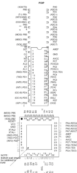
Pin Configurations
Figure 1-1. Pinout ATmega16A
PDIP (INT2/AIN0)
PB2
PA2 (ADC2) (OC0/AIN1)
PB3
Bottom pad should be soldered to ground
TQFP/QFN/MLF
(S
1.
Overview
The ATmega16A is a low-power CMOS 8-bit microcontroller based on the Atmel AVR enhanced RISC architecture. By executing powerful instructions in a single clock cycle, the ATmega16A achieves throughputs approaching 1MIPS per MHz allowing the system designer to optimize power consumption versus processing speed.
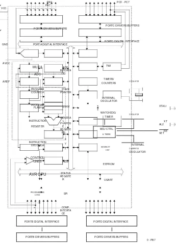
2.1 Block Diagram
Figure 2-1. Block Diagram
PA0 - PA7 VCC
PORTA DRIVERS/BUFFERS
GND PORTA DIGITAL INTERFACE
AVCC
PROGRAM STACK COUNTER POINTER
PROGRAM
SRAM FLASH
INSTRUCTION
GENERA L
REGISTER
PURPOS E REGISTE
RS
X INSTRUCTION Y
DECODER
Z
CONTROL
LINES ALU
AVR CPU STATUS REGISTE
R
PROGRAMMING SPI
LOGIC
PORTC DRIVERS/BUFFERS
PORTC DIGITAL INTERFACE
TWI
TIMERS/
OSCILLATOR COUNTERS
INTERNAL OSCILLATOR
XTAL1
WATCHDOG
OSCILLATOR TIMER
AL2 XT
MCU CTRL.
RE SET
& TIMING
INTERNAL INTERRUPT
CALIBRATED UNIT
OSCILLATOR
EEPROM
USART
0 - PB7
ATmega16A
[DATASHEET] 4
Atmel-8154CS-8-bit-AVR-ATmega16A_Datasheet Summary-07/2014 PORTB DIGITAL INTERFACE PORTD DIGITAL INTERFACE