Spatial Integration in Construction
Leonhard E. Bernold, M.ASCE
1Abstract: Work in construction always requires moving within, and interacting with, a complex environment while handling heavy materials and building elements to be joined, inserted, or aligned. Modern design software is able to digitally model all of those elements in their spatially correct configuration, and without interference. When it comes to the actual construction, however, the spatial models do not find any use. Twenty years after the manufacturing industry began using electronic design data to control their machinery, construction is also getting ready to move away from its longstanding tradition of working with paper-based blueprints. The newest steps on the path toward the use of three-dimensional digital design data in support of site operation are stimulated by the global positioning system and the many uses of lasers. Surveying has always performed critical functions on construction sites, such as marking building layouts, anchor bolts, concrete formwork, or bridge bearings. The objective of spatial integration in construction is to digitally merge spatial design data with the digital model of equipment working on implementing the design. This paper will briefly review historical advancements in ‘‘perfecting’’ the surveying technology before presenting three examples of a quantum leap in the way we design, plan, and control construction projects in the future.
DOI: 10.1061/~ASCE!0733-9364~2002!128:5~400!
CE Database keywords: Surveys; Construction; Computer applications; Information; Global positioning.
Introduction and Background
Richard Tucker, recipient of the first Peurifoy Construction Re-search award in 1986, posed the following question: ‘‘Are our systems truly control systems or merely advanced versions of documentation?’’~Tucker 1988!. In an attempt to answer his own question, he referred to the construction records from a thirteenth century castle project for King Henry III. Through this example he was able to demonstrate that documentations of 1986 were indeed almost identical to those used and perfected 800 years ago. The article also pointed to some remarkable advancements, in-cluding ‘‘radar surveying has done away with the old laborious transit, rod, and chain’’~Tucker 1988!. Notwithstanding those ex-amples, Tucker maintained that ‘‘the construction industry, how-ever, has a need for more dreamers. Construction research de-mands more quantum leaps . . . .’’
The successful launch of the global positioning system~GPS!
for private use and the advancement of laser technology laid the foundation for rapid advancements in surveying technologies after 1986. By comparing construction magazines from the mid-1980s with today, one is struck by the amount of advertisements and articles about modern surveying methods. Nevertheless, one could compare the efforts of improving surveying with the efforts in perfecting the buggy whip. ‘‘Even with the perfect buggy whip, man would still prefer to fly,’’ concludes Tucker ~1988!. This paper builds on this viewpoint by first reviewing the historical
efforts to ‘‘perfect’’ surveying before presenting research work geared toward leaping forward in the way we model and control construction projects on-site.
The accurate positioning of any civil structure under or above ground is critical to the success of a construction project. Trian-gulation with angle measuring theodolites, in combination with measuring tapes, was, until recently, the most commonly used method for establishing construction control points. In the past, surveyors and surveying equipment were independent agents for laying out the position of critical building elements, and for checking as-builts. In the immediate past, laser technology has eliminated the necessity to sequence surveying from the actual construction by allowing one to do them in parallel. Omni-directional laser reflectors have been attached to climbing con-crete formwork for instantaneous position control. Subsequently, they have been attached directly to construction equipment, such as paving machines and graders. This constitutes a major step toward a spatially fully integrated construction site because accu-rate positions of key physical items on-site have to be established in real time.
It seems that spatial positioning using laser technology com-bined with electronic communication will change the way con-struction is done. Apparent benefits come from several areas—~1!
spatial guidance for operators ~e.g., equipment and tools are shown relative to desired position!; ~2! diminished amount of rework due to reduced errors~e.g., elimination of blueprints and staking!; and~3!closing down of position checking~e.g., grades in complex cuts!. First tests with prototype technologies seem to indicate that it is not only possible to reduce needed manpower in dangerous work zones, but to also allow the operators to be dras-tically more spatially accurate; most important, it makes them much more independent of second-party constraints~e.g., check-ers of grade!.
It is not long ago that spatial interference checking and virtual walkthroughs were exciting features of new computer-aided-design packages, which result in many cost savings on construc-1Associate Professor, Dept. of Civil Engineering, North Carolina State
Univ., Raleigh, NC 27695.
Note. Discussion open until March 1, 2003. Separate discussions must be submitted for individual papers. To extend the closing date by one month, a written request must be filed with the ASCE Managing Editor. The manuscript for this paper was submitted for review and possible publication on January 24, 2000; approved on November 7, 2001. This paper is part of the Journal of Construction Engineering and Manage-ment, Vol. 128, No. 5, October 1, 2002. ©ASCE, ISSN 0733-9364/ 2002/5-400– 408/$8.001$.50 per page.
tion sites. The industry seems to have advanced to a new era of measuring and presenting spatial information about objects it con-structs. What are some of the new opportunities that present themselves? Before introducing several field-tested prototypes, the paper presents a brief history of surveying as the primary method for defining spatial positions and relationships in the past.
From Plumb Bob to Satellites
The art of measurement possibly began when our ancestors started to shape the earth to create shelter, to grow food, or to hunt large animals. Water had to be led by sloped canals into fields for irrigation. Structures were erected to house the gods and people. One way or the other, it was necessary to put things together in such a way that the law of physics~e.g., gravity!could be brought to bear. Ensuring that a wall was vertical, the lengths of columns were equal, or the slope of a canal was constant was as important as good mud and solid rock.
There are several books that have been used to present the highlights of the past developments of surveying. Some of the authors include Kavanagh and Bird~1992!, Wilford~1982!, Rich-eson ~1966!, and Peters~1981!. The following section will pro-vide a synopsis of some important steps in its evolution.
Ancient Surveying
The Sumerians and the Egyptians used various techniques to plan and build their cities, as well as to design and build their agricul-tural fields. Some of the early Sumerian attempts were recorded on clay tablets that still exist today, and stones used to mark off boundary plots of land have been preserved. The Egyptians re-corded their surveys on the tomb walls of prominent Egyptians. The recorded information gave the dimensions, area, quality, and dues required for the given property.
As today, the quality and the accuracy of the survey were only as good as the instrument being used and the person using it. Their techniques and the lack of equipment limited ancient sur-veyors. In most cases, the ancient surveyor used cords and rods with undetermined and nonstandardized lengths to measure dis-tances. Due to this, most distances surveyed were only good to the person who measured them. Surveying techniques had not been standardized, had to be learned by trial and error, and were passed down from master to apprentice.
The development of geometry by the Greeks expanded survey-ing techniques. The Greeks were much more advanced in their record keeping, and gave information regarding detailed dimen-sions of the land, ownership, and the quality of the land. Their records also indicate the transfer of Greek methods and instru-ments to the Romans, who used a variety of instruinstru-ments for the construction of roads, irrigation systems, canals, and likewise. Their line-measuring instruments included wooden rods, cords, and possibly some form of a taximeter. They used two different forms of levels. The first form depended on the principle that the surface of a liquid in repose is horizontal. These instruments were known as chorobates, and consisted of a trough partly filled with a liquid. The second form of instrument depended on the principle that lines perpendicular to a vertical line are horizontal. These instruments were usually equipped with a plumb bob.
Surveying from Medieval Times to Industrial Revolution
One of the major contributions to surveying came with the devel-opment of the magnetic compass. It is known that the Chinese
were using the compass during the eleventh century, but it is believed that they were using it much earlier than this. The first reference to the nautical use of the magnetic needle in Europe was in 1180 A.D. by Alexander Neckham. However, in 1269, a French soldier, Peter Peregrinus, gave the first technical description of the compass. The 32 divisions represented the winds, and by 1500 they were labeled as N, NNE, NE, E, SSE, and so on. Modifica-tions had to be made before this marine compass could be used on land. The next great surveying instrument to be developed was capable of giving the combined altitude and azimuth reading. This instrument, known as a Polimetrum, was a prototype of the mod-ern theodolite. Around 1529, Gemma Frisius described a new method of land surveying, known as triangulation, and he devised a new instrument to perform these surveys. The invention of these instruments and the development of these new surveying methods served as a major step in surveying. Distance measuring devices included wheeled instruments known as odometers and perambu-lators. But surveyors felt that these instruments were not accurate enough. In 1620, Edmund Gunter invented what is known today as the Gunter’s chain, which became the instrument of choice for distance measurements.
The average land surveyor did not have the mathematical background to use the methods or the funds to buy the instru-ments. For this reason, the plane table and sight was developed and used during the sixteenth and seventeenth centuries. This table could be constructed easily and could be used as a rule-of-thumb method of operation. As shown in Fig. 1, the plane table consisted of a smooth drawing board mounted on a tripod and a metal sight rule ~alidade! for accurate aim on the object to be plotted. Telescopic sights, magnetic compasses, and clamps for holding down the drawing paper were added later. This table could easily handle the new methods of triangulation.
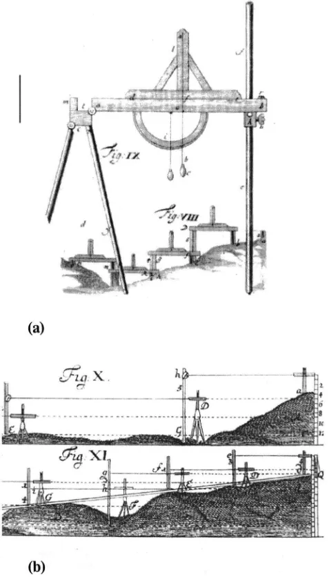
Leupold ~1727!introduced leveling in his book. ‘‘Leveling is the science of how to determine, with suitable instruments, which of two points is further removed from the center of the earth’’
~Jensen 1969!. A common instrument used on construction sites using a plumb bob is shown in Fig. 2~a!.
Leupold ~1727!provided the instructions on how to make a workable spirit level the ‘‘mother’’ of today’s carpenter level. ‘‘A straight, smooth glass tube is used, with a maximum internal di-ameter of 12inch@~1.27 cm!#and closed at one end. It is filled up, except for one drop, with a liquid which does not freeze. After-Fig. 1. Seventeenth century surveyor assisted by cherubs using Gunter’s chain~Leupold 1727!
wards the tube is sealed airtight. If the tube is held exactly hori-zontal, the bubble rests in the middle, but if one end is slightly lifted, the bubble moves immediately to that end’’~Jensen 1969!.
Early American Surveying
The settlement of the British colonies in America brought about a new breed of surveyor. The terrain was much more rugged, and instruments, such as the theodolite, were not well suited. The early theodolites were heavy and bulky, and were best used on cleared lands rather than dense forest. ‘‘Colonial surveyors were generally men who possessed a rugged constitution, a basic un-derstanding of mathematics, and the essential tools of the trade, usually@a#plane table, chains, and a surveying compass known as a circumferentor’’ ~Wilford 1982!. Initially, the main job of American surveyors was to establish boundary markers. Unfortu-nately, the accuracy of these early surveyors left a lot to be de-sired, and boundaries were routinely resurveyed.
It is no surprise that Thomas Jefferson, who was a trained surveyor himself, made some important contributions to the field.
For one, he provided basic training to Lewis Meriwether in the use of astronomical and surveying instruments, before ensuring that Meriwether received further instruction from Robert Patter-son, professor of mathematics, and Major Andrew Ellicott, a pre-mier surveyor of his time. While Lewis’ surveying capabilities were critical in securing for the colony the western territories, including the northern part of Louisiana, Jefferson may be con-sidered the ‘‘father’’ of the tape measure. Since Lewis and Clark had no space to take measuring chains or measuring rods on their trip, Thomas Jefferson suggested to take the following item along: an ‘‘instrument for measuring made of tape with feet & inches marked on it, confined within a circular lethern@sic#box of suf-ficient thickness to admit the width of the tape which has one of its ends confined to an axis of metal passing through the center of the box, around which and within the box it is readily wound by means of a small crank on the other side of the box . . . ’’~Bedini 1990!.
Enabling Grand Projects
The construction of the Suez Canal, 1861–1868, was, in many ways, one of the key projects of the nineteenth century. A new law implemented in 1863 forced the management to replace 20,000 slaves with machines. Thus, it was the first time that fleets of large construction equipment replaced human power as a main means of construction. As depicted in Fig. 3, surveying played a major role in the success of the project.
The Suez Canal also serves as a case study that illustrates problems the state-of-the-art surveying technology was facing at that time. In 1789, the French engineer Lepere was commanded by Napoleon to study the feasibility of building a canal between the Red and the Mediterranean Seas. Due to a surveying error, he came up with a 9,908 m difference between their surface levels. It was not until 1833 that this error was discovered when another survey was conducted. Thus, the surveying errors caused a 40 year delay of the project. Other projects that depended heavily on the science of surveying were~1!several long railway tunnels in Europe; ~2!the Eiffel Tower; ~3! the Brooklyn Bridge; ~4! the Firth of Forth Bridge; ~5! the Crystal Palace Building for the World Exhibition in London, 1851; and ~6!the Galerie des Ma-chines for the World Exhibition in Paris, 1889. Nothing contrib-uted as much to the advancement of surveying technology as the introduction of invisible light to measure very accurately the dis-tance between a transmitter, combined with the theodolite, and a receiver.
Fig. 2.Leveling instruments and methods of seventeenth century:~a!
leveling techniques for short small areas;~b!large scale leveling for road or water projects~Leupold 1727!
Fig. 3. Surveying station during construction of Suez Canal, 1860
~Peters 1981!
From Theodolites to Total Stations
The original theodolites had very long telescopes. Over time, im-provements were made, and the telescope was eventually short-ened to the point that it could be rotated 360° about its horizontal axis. This act of rotating the telescope became known as transit-ing, and the theodolites were known as transiting theodolites, eventually shortened to transits ~Kavanagh 1989!. Transits use a four-screw leveling base, while today’s theodolites use three screws. Further improvements to theodolites have led to the elec-tronic distance measurement instruments~EDMIs!, also known as a total station. EDMIs, first introduced in the late 1950s, measure the time it takes for either infrared or microwaves with known speeds to cover an unknown distance. Systems employing infra-red require a transmitter at one end and a reflecting prism at the other end of the line being measured. Total stations typically con-sist of an electronically digitized theodolite, with a built in EDMI, an onboard microprocessor, a data collector, and a data commu-nication interface.
Global Positioning System
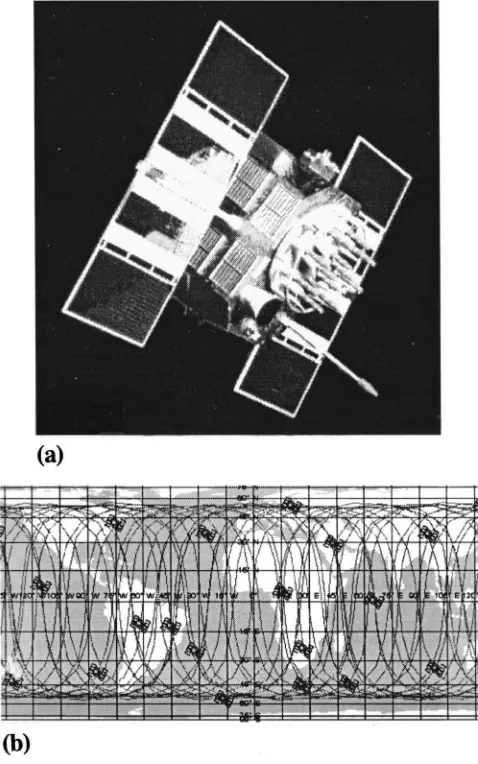
On July 17, 1995 the U.S. Air Force announced that the GPS satellite constellation had met all requirements for full operational capability. This declaration signaled the culmination of more than 20 years of research, development, and implementation activities that brought the revolutionary navigation system from concept to reality. The program was created by the Department of Defense in 1973. The first GPS satellite, a Block I developmental model, was launched in February, 1978. GPS, operated by the 2nd Space Operation Squadron of the 50th Space Wing at Falcon Air Force Base, Colo., is a U.S. Department of Defense radio navigation system. It provides highly accurate, real-time, all-weather posi-tion, velocity, and time information to properly equipped air, land, sea, and space-based military and civilian users around the world. There are 27 satellites in the GPS operational constellation, which provides most users visibility to five to eight satellites from any point on earth. Fig. 4 presents the positions of the 27 satellites, at a particular date, together with their orbital paths on September 29, 1998 at midnight.
Determination of the four dimensions ~X, Y, Z, and Time! re-quires at least four satellites. Most receivers convert the position signals into geodetic latitude, longitude, and height above sea level, but these receivers can often be set to convert the signals to other user defined systems. Precise positioning using GPS receiv-ers at reference locations provides corrections and relative posi-tioning data for remote receivers. Another common method that is used to gain higher accuracy is called differential GPS; it is ca-pable of overriding a bias error at an unknown location with the measured bias error at a known position.
State of Practice in Spatial Positioning
The majority of construction surveying today is performed with levels, theodolites, many varieties of lasers, total stations, and GPS integrated total stations.
Levels
Keeping window sills, floors, and structures level is still a re-quired task for any construction worker. As Fig. 5~a!shows, the spirit level from the seventeenth century is still used for that purpose. Lasers, as seen in Figs. 5~b and c!, are also being used as
invisible markers and have become one of the most prominent instruments. Laser levels are deployed during clearing and grad-ing, to set up batter boards on foundations, or to maintain the plumbness of masonry walls. Rotating lasers direct the installa-tion of doors and windows, and assist in the leveling of cabinets and shelves.
Line and Grade Lasers
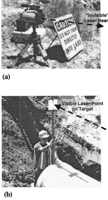
The plan and profile of sewers have to be translated into fixed points to prepare the bedding and to position each piece of pipe. The traditional method of batter boards and grade rods has been replaced by beam-lasers, as shown in Fig. 6. Since the pipes con-nect manholes in a straight line and in a constant slope, properly calibrated beam-lasers provide a perfect lead combining both line and grade in a single beam.
As Fig. 6~b! demonstrates, the invisible laser light becomes visible when it hits a solid surface, such as a white plastic. The goal of the pipe layer is to set the pipe-bell in such a way that the vertically held rod mounted target is being hit in the center by the laser beam. The pipe can be readjusted by moving the pipe hori-zontally and by adding more material to the bedding.
Fig. 4.GPS satellites and their orbits:~a!deployed GPS satellite;~b!
satellite positions at midnight on September 29, 1998~Dana 1998!
GPS without Degradation
On May 1, 2000, an important hurdle to the wider use of GPS in construction came down when the United States stopped the se-lective availability degradation of GPS, which improves the ac-curacy of pinpointing positions tenfold. The objective of this re-markable step, as stated by the U.S. president, was to encourage the private sector to increase its use of U.S. GPS technologies and services worldwide. How this decision will affect the use of GPS in construction is still unclear, since a tenfold improvement is not enough to meet the more stringent requirements.
Integrated Surveying
The term ‘‘integrated surveying’’ has been coined to mean the integration of terrestrial and GPS technologies into one unit
~Trimble 2000!. For example, Trimble’s Geodimeter ATS-MC system is specially designed for real-time position control and guidance of machines in three dimensions. This concept has, as its name implies, surveying as its foundation. The goal is to provide the user with real-time data about the position in space and dis-tance to a target position in X, Y, and Z. It requires special preci-sion instruments, line of sight, and skills to operate it. The
Site-Vision GPS grade control ~Trimble 2000!, on the other hand, allows a dozer operator to view the position of the dozer blade relative to where it should be, indicated by the site plan. While the early grade control system using lasers allowed only its use in one and the same plane, these newer systems are three dimensional, allowing them to follow the intricate surfaces of golf courses with a large dozer blade.
Integrated surveying can be considered the state of the art in spatial integration. The objective of the research, at this point, is to investigate how general construction and construction equip-ment can be spatially integrated with design and planning tools. The following section will address this question by presenting several such prototype systems that have been tested in different fields of construction.
Design Integration of Construction Equipment
A technology that has long found its way into manufacturing is computer-aided design ~CAD! integrated with computer-aided manufacturing. The cornerstone of this approach is to communi-cate design information from a computer used for design directly to computers used to control machines in the fabrication shop without reentering data. Intelligent systems are able to schedule the work and to initiate start-up action ~e.g., tool calibration!
without any human intervention ~Bernold and Reinhart 1990; Fig. 5. Common leveling instruments in construction, 1999:~a!
car-penter’s bubble level;~b!optical laser level;~c!rotating laser
Fig. 6. Line and grade laser for drainage pipe installation: ~a! in-stalled and calibrated laser above ground;~b!laser target held vertical with bubble level
Salim and Bernold 1994!. The key problem in achieving the same in construction was the lack of electronic enabling technologies that ~1!allow the construction equipment to receive design data electronically;~2!generate information about their own condition and performance in real time; and~3!communicate with a higher level of job planning and control systems. In the meantime, how-ever, the emergence of hardened electronic sensors, affordable small video, the Internet, and wireless data communication did remove key barriers to integration. In a fully integrated structure, project participants, management systems, equipment, equipment operators, support devices, and even the building itself would communicate with each other in both an active and a passive mode. It is apparent that not all of the elements mentioned need to be interfaced at one time in order to create new and meaningful solutions. The following discusses three applications that differ in the range in which they apply those new devices and concepts.
Remote Position Control
To accurately position large objects in construction, such as con-crete pipes, normally requires the presence of a human to physi-cally maneuver the object into its final place. Because most of these positioning tasks take place either in confined spaces, such as trenches, or in elevated locations, such as steel frames, the laborers are exposed to significant dangers. Eliminating such dan-gerous work situations requires the replacement of the direct human handling of the object with the precise maneuvering by an equipment operator ‘‘far away.’’ Steps that make this possible include ~1!providing the operator spatial information about the object he/she controls; and ~2! providing the operator with a mechanism that will allow him/her to be as exact in operating the actuator as the task requires. Placing large water and sewer pipes into the trench at the right line and grade serves as an example to illustrate how remote positioning could be implemented.
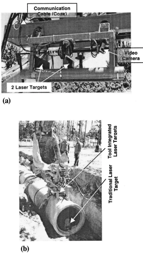
Designed to assimilate most easily with presently deployed methods and tools, the pipe manipulator is designed as an attach-ment to a backhoe excavator, and interfaces easily with traditional line-grade lasers. Hydraulic motors and cylinders provide the force necessary to rotate and push the pipe into place, while video cameras communicate visually the position of the laser and laser targets to the operator. Fig. 7 presents the hardware and illustrates the technology that underwent comparative field tests on Septem-ber 13, 1999.
Fig. 7~a!depicts how two laser targets and two video cameras are built into the pipe manipulator that attaches to the excavator bucket, shown in Fig. 7~b!. With the close-up views of the laser targets and the end of the pipe that has to be joined, the backhoe operator is able to guide the pipe into place and join it using a simple control box positioned inside the cabin. The field test was executed by a trenching crew from ABE Utilities, Inc., Raleigh, N.C. Two line and grade lasers, one from the contractor inside the pipe and one above the pipe, were installed at the beginning of the pipeline. It was interesting to observe the enthusiastic response by the operator, who especially cherished the availability of a close-up live camera picture from an area that he normally does not see. During the field test, nine 2.4 m~8 ft!long pieces of pipe were successfully placed, as shown in Fig. 7, at a cost that matched the traditional method of pipe laying.
The presented case can be considered as spatially integrated tele-operation. Tele-operation is nothing new. It is being utilized in many other areas, even within construction, where it sometimes serves as the key enabling technology~e.g., microtunneling!. This method of relative position control is most applicable where
pre-cise maneuvering of a heavy load at a distance, and close to a target, would either allow a new way of doing things or eliminate a dangerous work zone.
Remote position control does not concern itself with the posi-tion of the equipment within the coordinates of the construcposi-tion site. Rather, the focus is on establishing the accurate spatial rela-tionship of the construction element~e.g., steel beam!with a tar-get ~e.g., connector on steel column!. The goal of spatially inte-grated systems, however, is to merge the equipment unit with the entire design within one coordinate frame. The remaining part of the paper will discuss two specific applications of spatial integra-tion.
Design-integrated Excavation
Three-dimensional CAD representations of excavation jobs are simply digital models of surfaces or objects that represent trenches, ditches, pits, etc. within a chosen coordinate structure. A design-integrated system would have to combine the digital model of the job with the spatially correct model of the excavator. Fig. 7. Technology for precise placement of heavy pipe: ~a! hard-ware enabling remote position control;~b!integrated manipulator at-tachment
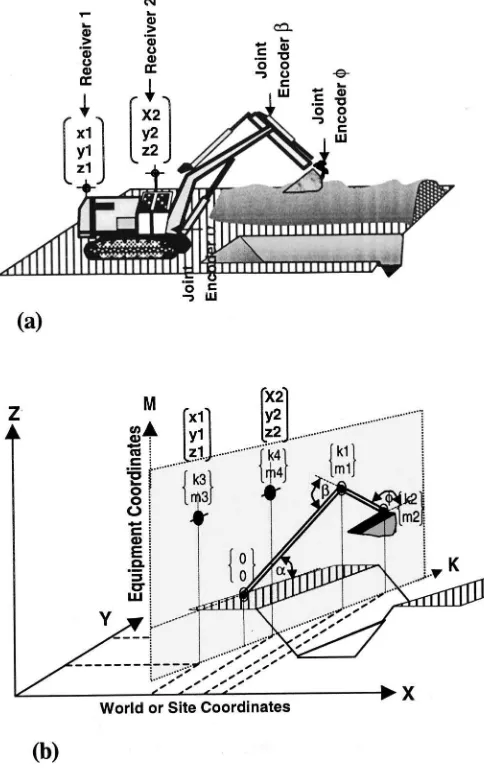
Thus, an equipment operator would be presented with detailed data about the position and orientation of each part of the machin-ery, as well as with nonvisible or hard to see objects, such as pipes buried in the ground or cables suspended in the air. Fig. 8 depicts schematically how the 2D coordinate system of a backhoe excavator is merged into the coordinate system of the jobsite.
Fig. 8 shows the physical representation of the equipment working on a trenching operation. Also illustrated are three elec-tronic joint encoders that provide real-time data about the position of the boom relative to the selected origin. The interface with the site coordinate frame is established by two laser receivers mounted on the top of the backhoe in the same plane as the boom, stick, and bucket. A detailed presentation of the hardware can be found in Huang and Bernold~1997!. As indicated in Fig. 8~b!, the coordinates of the boom joints, as well as their position in the site coordinate system, can be calculated trigonometrically, utilizing the data provided by the two receivers. As a result, the precise location of the bucket, relative to the design, represented by the sloped trench, can be shown on a cab-mounted monitor. If the sensors are read, and the calculations are repeated several times per second, the operator is able to monitor how the CAD model of his/her machine changes every time he/she moves one part of it within the construction site. Fig. 9 shows how this was accom-plished for a prototype system.
As seen in Fig. 9~a!, a picture taken during prototype testing in the field, the operator has in front of him/her a flat screen that shows him/her the contour of the excavator in three different views within the construction site environment. Zooming allows him/her to focus on any spatial area within the site. The spatial positioning system used during the test calls each receiver five times per second ~5 Hz!to check if its status has changed from the previous time, after which each excavator element is recalcu-lated and redrawn on the screen. It is apparent that errors in en-coding, as well as slight modifications in the system, will impact its accuracy. To identify and correct such errors, recalibration pro-cedures have to be implemented. Fig. 10 demonstrates how a backhoe can be calibrated through touching a rod with known coordinates.
To execute a meaningful calibration, it is necessary to use more than one known point~e.g., rod!and to test different boom angles. It is apparent that system calibration is important, and can be accomplished in many different ways. In preliminary tests that were conducted with the above prototype system, the accuracy during digging was within 5.1 cm~Huang and Bernold 1997!.
The backhoe excavator exemplifies a group of construction equipment that can be easily fit with the necessary devices to be Fig. 8. Spatial integration of excavator and trench design:~a!model
of physical relationships;~b!integration of two coordinate systems
Fig. 9. Design-integrated excavator in field:~a!view from cabin;~b!
integration in CAD
Fig. 10. Recalibration of design-integrated excavator: ~a! bucket touches rod;~b!predefined point
interfaced with a spatial positioning system. Another group, rep-resented by the omnipresent crane, requires more extensive up-grading.
Design-integrated Craning
Cranes come in different forms and shapes, but they all depend on a vertical hoist line that is suspended from a support frame. The spatial position of the hook is visually established by the crane operator or a helper communicating with a hand signal or radio to the operator located high up underneath the horizontal jib or in the cabin of a crawler- or truck-crane. By simple observation, one realizes that this kind of rigging system does not lend itself to positioning, orienting, or installing a building element according to the design. Two capabilities have to be added to the traditional craning technology—~1!a device or method to connect elements when suspended by the crane; and~2!a mechanism to manipulate a load at the end of the hoist line. Both capabilities were devel-oped for erecting steel.
The patented~U.S. Patent No. 5,244,300!ATLSS connection
~AC!is comprised of a tapered ‘‘tenon’’ piece on the beam that slips into a ‘‘mortise’’ guide mounted on a column. The AC is self-guiding and self-centering. Both pieces are attached to their respective members in the shop, or on the ground at the site, to facilitate automated construction~Lawrence et al. 1993!. To take advantage of this new system, the use of remote position control, discussed earlier, would be sufficient. However, design-integrated craning supported by information technology will provide further opportunities.
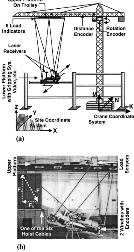
The inverted Stewart-platform ~Albus 1989!, which uses six hoist cables instead of only one, denotes a vastly different ap-proach to the single degree of freedom hoist cable. Key to this device are six cables that connect a larger upper platform to a smaller lower platform, as shown in Fig. 11.
Because each of the six cables has a horizontal force compo-nent, labeled Fh in Fig. 11~b!, the lower platform is spatially constrained. Furthermore, if each of the six cables can be oper-ated independently, the platform has six degrees of freedom, and can be easily maneuvered into a wide range of orientations, as demonstrated in Fig. 11~b!. If the upper platform is attached to the boom of a crane, the system is now able to pick up beams or columns, swing them into place, and hold them precisely at a required location. Fig. 11~a!depicts an erection process of a steel building that uses the ATLSS connector, described earlier. Similar to the design-integrated excavator, two fix-mounted laser receiv-ers provide accurate position data of two points, describing a unique line in 3D, within the site coordinate system. One addi-tional inclineometer, also based on the platform, is sufficient to define its spatial position, as well as its orientation. It is evident that, different than in the case of the excavator, the spatial posi-tioning system provides information about the location of the load
~e.g., steel beam!directly, but only when the two laser receivers are in line of sight with the transmitters, which can happen. In such cases, the sensors ~turret rotation, trolley distance, and six winch encoders! mounted on the crane system would automati-cally provide the same information, but only after proper calibra-tion. What is left is to connect the steel beam to the column by taking advantage of the AC system, mentioned before, a bolting, or a welding mechanism. Although the spatially integrated system will be able to provide accuracy sufficient for most applications, it will not be able to account for the accumulation of small errors within complex systems ~e.g., steel frame!. Here again, video cameras attached to the lower platform can be utilized to provide
the operator with the necessary visual information that will allow him/her to initiate the necessary maneuvers. Various task specific technologies could be affixed to the platform in support of other operations, such as placing concrete into a column formwork or laying brick with the help of a robotic bricklayer.
The three applications discussed in this section demonstrate the many possibilities for employing modern information technol-ogy, in combination with positioning systems, to create spatial integration between construction equipment, the environment, the physical sphere, and the digital representation of the structure being built. In all three instances, the character of the equipment changed from a mere ‘‘workhorse’’ to a precision tool comparable to a high-tech instrument used by a medical doctor.
Summary and Conclusion
The technology to determine horizontal distances, elevations, di-rections, and angles on the earth’s surface needed for property boundary location, construction layouts, and mapmaking has an Fig. 11. Site-integrated tower crane:~a! Stewart crane and attach-ments to erect steel;~b!Stewart crane during laboratory tests
interesting history. This paper highlights some of the historical steps in perfecting surveying technology, closing with the intro-duction of lasers and GPS as the latest of such instruments. It was then argued that the present state in surveying might be compared to the perfect buggy whip, which could invite a quantum leap in the way we construct. It is felt that through combining informa-tion technology, GPS, lasers, and other three-dimensional posiinforma-tion measurement devices, the pathway for a radical step, the real-time integration of construction equipment and project design into a unified coordinate system, has been opened. Two prototypes that have been implemented were used to outline the new paradigm needed to build spatially integrated systems that eventually would encompass all major equipment on construction sites, their opera-tors, intelligent site planning, and control networks. The fact that contractors have already successfully installed integrated survey-ing systems on dozers worksurvey-ing on complex-surface golf courses or parking lots indicates that a major segment of the industry may be ready to step into the realm of spatial integration. The writer is convinced that such a step will lead to drastic changes in the way we build, new methods, and radically different means of commu-nication, resulting in productivity, quality, and safety that are un-imaginable today.
Acknowledgments
This work was partially supported by grant number 50SBNB7C1250 from the National Institute of Standards and Technology. Its content is the sole responsibility of the writer and does not necessarily represent the official view of the National Institute of Standards and Technology. Also acknowledged are the contributions from assistants and colleagues who have been in-volved in developing many of the technologies mentioned in this paper.
References
Albus, J. S.~1989!. ‘‘Robot crane technology.’’ Final Rep., NIST Tech. Note 1267, National Institute of Standards and Technology, Gaithers-burg, Md.
Bedini, S. A.~1990!. Thomas Jefferson, statesman of science, Macmillan, New York.
Bernold, L. E., and Reinhart, D.~1990!. ‘‘Process planning for automated stone cutting.’’ J. Comput. Civ. Eng., 4~3!, 255–268.
Dana, P. H.~1998!. ‘‘The geographer’s craft project; Global positioning system overview.’’ Dept. of Geography, Univ. of Texas at Austin, Austin, Tex.
Huang, X., and Bernold, L.~1997!. ‘‘CAD-integrated excavation and pipe laying.’’ J. Constr. Eng. Manage., 123~3!, 318 –323.
Jensen, M. ~1969!. Civil engineering around 1700, Danish Technical Press, Copenhagen, Denmark.
Kavanagh, B. F. ~1989!. Surveying with construction applications, Prentice-Hall, Englewood Cliffs, N.J.
Kavanagh, B. F., and Bird, S. J. G. ~1992!. Surveying, Prentice-Hall, Englewood Cliffs, N.J.
Lawrence, W. S., Lu, L. W., and Viscomi, V.~1993!. ‘‘Advanced connec-tions reduce costs.’’ Modern Steel Constr.,~Dec.!, 16 –21.
Leupold, J. ~1727!. Theatrum aritmetrico geometricum: Rechen- und messkunst, Leipzig, Germany.
Peters, T. F. ~1981!. Time is money, Julius Hoffman Verlag, Stuttgart, Germany.
Richeson, A. W. ~1966!. English land measuring to 1800: Instruments and practices, The Society for the History of Technology and MIT Press, London and Cambridge, Mass.
Salim, Md., and Bernold, L. E. ~1994!. ‘‘Effects of design-integrated process planning on productivity in rebar placement.’’ J. Constr. Eng. Manage., 120~4!, 720–738.
Trimble, Inc.~2000!.^http://www.trimble.com/& ~Nov. 26, 2001!. Tucker, R.~1988!. ‘‘Perfection of the buggy whip.’’ J. Constr. Eng.
Man-age., 114~2!, 157–171.
Wilford, J. N.~1982!. The mapmakers, Random House, New York.