Procedia Engineering 54 ( 2013 ) 875 – 884
1877-7058 © 2013 The Authors. Published by Elsevier Ltd.
Selection and peer-review under responsibility of Department of Civil Engineering, Sebelas Maret University doi: 10.1016/j.proeng.2013.03.080
The 2nd International Conference on Rehabilitation and Maintenance in Civil Engineering
Investigating and Comparing Traffic Induced and Restrained Temperature
Stresses in a Conventional Rigid Pavement and Semi-Rigid Layers
A. Setyawana*, S.E. Zoorobb , and K.E. Hasanb aDepartment of Civil Engineering, Universitas Sebelas Maret, Indonesia
b
Department of Civil Engineering, University of Leeds, UK
Abstract
The paper investigates and compares the magnitude of restrained temperature stresses that can be achieved in both a rigid pavement and a flexible pavement with a grouted macadam surfacing. The analysis is based on well known Westergrad equation that commonly applicable for concrete and BISAR from Shell that used for flexible pavement A hypothetical pavement is designed to assess the properties of the materials under traffic induced stresses and temperature restrained stresses. The results indicate that grouted macadams could be as vulnerable to combinations of thermal and traffic stress as concrete and with respect to traffic induced stresses
slab and BISAR is more suitable for grouted macadam surfacing
© 2012 Published by Elsevier Ltd. Selection and/or peer-review under responsibility of Department of Civil Engineering, Sebelas Maret University
Keywords: traffic stresses; rigid pavement; semi rigid; temperature.
1. Introduction
Currently, there are no fundamentally based analysis techniques for the design of pavement composed of grouted macadam layers. It is common practice for a pavement containing grouted macadam layers to be designed by treating the structure as a conventional flexible pavement and once the design thicknesses of the various layers have been determined to simply substitute the uppermost or top two layers with grouted macadam layers. Stresses in rigid pavements are well known to result from a variety of
* Corresponding author.
E-mail address: [email protected]; [email protected]
© 2013 The Authors. Published by Elsevier Ltd.
causes, including wheel loads, cyclic changes in temperature (warping and shrinkage or expansion), change in moisture content, and volumetric change in the subgrade or base course. These changes tend to deform the slab, causing stresses of widely varying intensity. In addition, the magnitude of stresses depend upon continuity of subgrade support. This paper investigates and compares the magnitude of restrained temperature stresses that can be achieved in both a rigid pavement and a flexible pavement with a grouted macadam surfacing.
2. Design Example Using Hypothetical Pavements
For this design example, a rigid pavement and a flexible pavement were both designed for a life of 20msa. The layer thicknesses calculated for both hypothetical pavement designs are summarised in Figure 1, the material properties are presented in Table 1
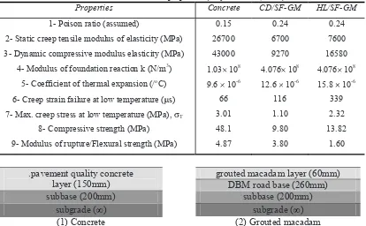
Table 1. Pavement material properties (Setyawan et al, 2003)
Properties Concrete CD/SF-GM HL/SF-GM
1- Poison ratio (assumed) 0.15 0.24 0.24
2- Static creep tensile modulus of elasticity (MPa) 26700 6700 7600
3- Dynamic compressive modulus elasticity (MPa) 43000 9270 16580
4- Modulus of foundation reaction k (N/m3) 1.03 108 4.076 108 4.076 108
5- Coefficient of thermal expansion (/oC) 9.6 10-6 12.6 10-6 15.8 10-6
6- Creep strain failure at low temperature ( s) 66 116 339
7- Max. creep stress at low temperature (MPa), T 3.01 1.10 2.32
8- Compressive strength (MPa) 48.1 9.80 13.82
9- Modulus of rupture/Flexural strength (MPa) 4.87 3.80 1.60
.pavement quality concrete layer (150mm)
grouted macadam layer (60mm) DBM road base (260mm)
subbase (200mm) subbase (200mm)
subgrade ( ) subgrade ( )
(1) Concrete (2) Grouted macadam
Figure 1. Design thicknesses of the pavement construction types considered
3. Comparing the Performance of Rigid and Grouted Macadam Surfaced Pavements Against Thermal and Traffic Induced Stresses
3.1.End restrained compressive stress
If a slab is located between rigid abutments without space for expansion, an increase of temperature above the temperature at the time of placing will induce an internal compressive stress. If the coefficient of linear expansion of the concrete is and the rise of temperature is t, then the strain induced in a concrete will be ( t) and the compressive stress in the concrete can be determined using Equation 1.
= (1)
where: E = elastic modulus of the concrete (MPa), = coefficient of thermal expansion (/ C) and t = temperature difference ( C).
The maximum temperature range which a concrete slab is likely to experience is +3 to +30 C (Croney and Croney 1997). In the following evaluation, a maximum temperature difference of 27 C was adopted. A comparison between the end restrained compressive stress for the design concrete slab and the grouted macadam surfacing is shown in Table 2.
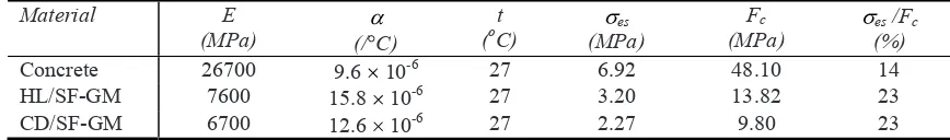
Table 2. Evaluation of end restrained compressive stress
Material E
(MPa) (/ C)
t (oC)
es (MPa)
Fc (MPa)
es /Fc (%)
Concrete 26700 9.6 10-6 27 6.92 48.10 14
HL/SF-GM 7600 15.8 10-6 27 3.20 13.82 23
CD/SF-GM 6700 12.6 10-6 27 2.27 9.80 23
This design example assumes that the grouted macadam layer can to some extent slide on its support in response to temperature change. The example also assumes the grouted macadam surfacing to be divided into 5 10m slabs. When the results are analysed in terms of the ratio between end restrained compressive stress and the maximum compressive strength of the materials, the relative stresses in the grouted macadam construction were found to be slightly higher than those in concrete. However, it is expected that compressive type failures are no more likely to occur in an end restrained grouted macadam slab than in a concrete slab of similar dimensions..
3.2.Foundation restrained stress
The opening and closing of joints in a concrete road causes sliding between the slab and its foundation (subbase or subgrade), or in extreme cases shearing within the foundation itself. The friction between the slab and its foundation will thus generate, in a slab not subject to end restraint, a compressive or tensile stress depending on whether the slab is increasing or decreasing in temperature. On the underside of the slab the stress due to foundation restraint will be compressive during expansion and tensile during contraction. Based on a method originally developed for concrete roads (RRL 1955) the stress due to foundation restraint can be calculated using the Equation 2.
= + (2)
= (3) where : fr = foundation restraint stress (MPa), L = slab length (mm), h = slab thickness (mm),
temperature change ( C), = coefficient of linear expansion, E = modulus of elasticity (MPa),
Q = Frictional restraint per unit area of foundation (MPa), = displacement needed to produce slipping (mm), y = distance between midpoint of slab and point at which maximum subgrade restraint is developed.
The value of Q and depend on the interface condition beneath the slab, and typical values derived from the measurements by Sparkes (Sparkes 1939) and Goldbeck (Goldbeck 1924) as used in Road Research Laboratory (RRL 1955) are listed below in Table 3.
Table 3. Typical values of frictional restraint and restrained length change
Interface condition Foundation restraint
stress (kN/m2)
Displacement for slip (mm)
Very smooth compacted sand or gravel. Smooth covered with waterproof membrane
5 0.25
Moderately smooth sand or gravel. Rough covered with waterproof membrane
10 0.75
Rough 15 1.25
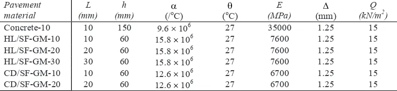
For the design example, a rough interface condition was chosen, and the pavement layer data are summarised in Table 4.
Table 4 . Pavement layer data for foundation restrained stress
Pavement
By substituting the data in Table 5 into equation 3, the equation simplifies into a simple quadratic equation of the following form:
ay2 by +c = 0 (4)
Values of y were then calculated using equation 5, shown below.
, = ± (5)
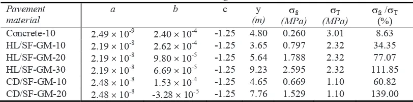
assumed to act uniformly over the whole cross section of the slab, a thinner grouted macadam layer results in higher foundation restraint stress.
Table 5. Parameters used for calculating the foundation restraint stress
Pavement material
a b c y
(m)
fr
(MPa)
T
(MPa)
fr / T
(%) Concrete-10 2.49 10-9 2.40 10-4 -1.25 4.80 0.260 3.01 8.63 HL/SF-GM-10 2.19 10-8 2.62 10-4 -1.25 3.65 0.797 2.32 34.35 HL/SF-GM-20 2.19 10-8 9.80 10-5 -1.25 5.64 1.788 2.32 77.07 HL/SF-GM-30 2.19 10-8 6.69 10-5 -1.25 9.23 2.595 2.32 111.85 CD/SF-GM-10 2.48 10-8 1.53 10-4 -1.25 4.65 0.669 1.10 60.82 CD/SF-GM-20 2.48 10-8 -3.28 10-5 -1.25 7.76 1.529 1.10 139.00
3.3.Thermal warping stress
A concrete pavement slab under load deforms in a characteristic saucer shape depending upon the position, magnitude, and area of contact of the load on the pavement surface. The resistance to deformation depends upon the stiffness of the supporting medium, as well as upon the flexural stiffness of the slab. The relative stiffness of the slab and subgrade is defined as in Equation 5 as follows (Westergaard 1927):
= (6)
where: l = radius of relative stiffness (m). It has lineal dimension and depends upon the properties of both the slab and foundation., E = modulus elasticity of the pavement (Pa), h = thickness of the pavement (m),
(typically 0.15), k = modulus of subgrade reaction (N/m3). It is assumed that the concrete pavement is laid on a typical subbase with a CBR value of 30%. The k value can be empirically related to the CBR value using the Equation 6 (DOT 1994)
k= ÷ . × . (7)
for a CBR value of 30%, the k value therefore equals 1.03 108 N/m3
For calculating the k value of a grouted macadam layer (which forms the upper part of a flexible bituminous pavement construction) the computer programme BISAR was used. Using BISAR, it was found that when a load of 9999 kN (maximum force allowed in BISAR) is applied on a standard loading plate of diameter 762mm, a deflection value of 53.79mm is obtained. Therefore, by extrapolation, the load required to produce a deflection value of 53.79mm deflection on the area of 1m2 is 21923 kN. By assuming linear elastic behaviour, the load required to cause 1000mm deflection on an area of 1m2 was calculated to be 407566 kN. A k value of 4.076 108 N/m3 was therefore adopted as the modulus of foundation reaction for the grouted macadam construction.. Thermal warping stresses consist of two types of stress, interior-warping stresses (Equation8 ) and edge warping stresses (Equation 9).
= (9) where: values of Cx and Cy depend on the slab length in the x (Lx) and y (Ly)
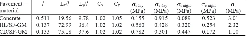
direction and the radius of relative stiffness (l) calculated from Equation 5. Lx and Lx are the free length and width, respectively. The values of Cx and Cx coefficients were developed by Bradbury (Bradbury 1938. Assuming the temperature gradient to be approximately linear with depth. Measurements of the temperature difference (in southern United Kingdom) taken at the surface, bottom and middepth at four equally spaced times in a year corresponding to the four seasons were used (Croney & Croney 1997). For this evaluation a temperature gradient of 4 C was selected for the maximum gradient at night and a temperature gradient of 7 C was selected corresponding to a summer period when the temperature amplitude at daytime is likely to be at its peak. The pavement data used for evaluating the thermal warping stresses are presented in Table 6.
Table 6. Pavement data used for evaluation of thermal warping stresses Pavement
Note: the E values used in the thermal loading calculations are the low temperature creep tensile values.
The values of l were calculated using Equation 5 and the data are presented in Table 7. Table 7. Pavement data for thermal warping evaluation
Pavement
3.4.Traffic induced stress
When a load is applied on the surface of a concrete slab, it will cause flexure of the slab thus producing tensile and compressive stresses. Three types of traffic loading on concrete slabs are normally considered: (1) Loading at the corners, (2) loading at the edge but away from the corner (edge loading) and (3) loading at a position away from the edges (interior loading).. The position and direction as well as the formulae originally derived by Westergaard to calculate the critical tensile stresses for each of these positions of loading are as follows:
(1) Loading at the corner: the corner loading stress ( c) at the top of the slab parallel to the bisector of the corner angle is expressed using Equation 10.
= . (10)
(2) Loading at the edge: the edge loading stress ( e) at the bottomof the slab parallel to the edge (Another smaller tensile stress will occur at the top of the slab at right angels to the edge) expressed by Equation 11.
= . + . log + log (11)
(3) Loading at the interior, the interior loading stress ( i) at the bottom of the slab and of the same magnitude in all directions, can be expressed with Equation 12.
= . log + log . (12)
where: P = wheel load (N), a1 = the distance from the corner to the centre of the load (mm), h = thickness of slab (mm), l = radius of relative stiffness, b = radius of equivalent distribution of pressure at the bottom of the slab (mm) The value is calculated from the Equation 13 and 14
= . + . for a 1.724h (13)
b = a for 1.724h a, (14)
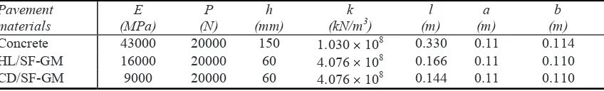
The data used in the design example for pavement layer evaluation against traffic induced stresses are presented in Table 8.
Table 8. Pavement data for traffic induced stress evaluation Pavement
materials
E (MPa)
P (N)
h (mm)
k (kN/m3)
l (m)
a (m)
b (m)
Concrete 43000 20000 150 1.030 108 0.330 0.11 0.114
HL/SF-GM 16000 20000 60 4.076 108 0.166 0.11 0.110
CD/SF-GM 9000 20000 60 4.076 108 0.144 0.11 0.110
Note: the E values used in the traffic induced stress calculations are the dynamic values.
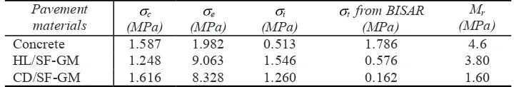
Table 9. Traffic induced stresses Pavement
materials (MPa) c e (MPa)
i (MPa)
t from BISAR (MPa)
Mr (MPa)
Concrete 1.587 1.982 0.513 1.786 4.6
HL/SF-GM 1.248 9.063 1.546 0.576 3.80
CD/SF-GM 1.616 8.328 1.260 0.162 1.60
The results indicate that, except for the corner loading stress, grouted macadams can potentially suffer much higher traffic induced stresses than concrete especially for edge loading situations, which are likely to exceed their modulus of rupture (Mr). The main
contributing factor being the lower thickness of the grouted macadam layer, which is less than half of the concrete thickness.
The results of interior loading stresses were compared to the results obtain from BISAR computer program by inputting the same pavement thickness and stiffness data. The results from BISAR indicated that the stress generated at the bottom of the concrete pavement was greater than those at the bottom of grouted macadam slabs. These results are contrary to the results of interior loading stresses based on Westergaard analysis of rigid pavements. The main contribution to this discrepancy is the different assumptions
two layered pavements (slab and subbase) are taken into consideration, whilst in a flexible multi layered pavements, as calculated using BISAR, all the pavement layers (surfacing, roadbase, subbase and subgrade) are considered in the analysis. The other key difference is that in BISAR the layers are assumed to be infinite in x and y directions. This would certainly be applicable in the case of grouted macadam surfacings which are specifically marketed as surfacings that do not require joints, but not so for a jointed concrete.
Therefore with respect to traffic induced stresses at the underside of the surfacing
BISAR is more suitable for grouted macadam surfacings (0.576 MPa).
The extensively high corner and edge traffic induced stresses calculated from
rapidly cause grouted macadam construction to fail at construction joints. Field observations of grouted macadam surfacings have not shown any such behaviour and therefore further use of these stress values was omitted.
4. Combination of Warping, Foundation Restraint and Traffic Induced Stress
Since concrete is very much weaker in tension than in compression, it is usually only necessary to consider the tensile stresses. However, it is not possible for all factors to produce stresses of maximum values simultaneously, the resultant stress will not therefore be as great as the sum of the maximum individual stress.
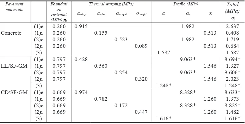
Table 10. Maximum tensile stresses in the pavements
Thermal warping (MPa) Traffic (MPa) Total
(MPa)
t
e-day i-day e-night i-night c e i
Concrete
Calculations of the worst case stress combinations that can result in critical tensile stresses in the different pavement constructions are summarised in Table 10. The last column in Table 10 shows that the maximum stresses that can generate in grouted macadam surfacings are greater than those in a standard concrete pavement. According to the Westergaard equations, the highest stress levels were mainly caused by traffic induced stress especially edge loading stresses which were far beyond the flexural strength of the materials.
The evaluations shown above indicate that grouted macadams could be as vulnerable to combinations of thermal and traffic stress as concrete. Not enough time was available in this investigation to cover this area more thoroughly and, more investigations into the thermal properties of grouted macadams are needed. Grouted macadam has been recognised to have properties that more like bituminous pavement than a concrete pavement (Anderton 2000), so that the design of flexible pavement is adopted for grouted macadam layer and the evaluation of grouted macadam layer as bituminous pavement has given satisfactory results. Evaluation of the grouted macadam layer as a rigid pavement with respect to traffic load resulted in poor pavement performance.
5. Conclusions
1. The evaluations indicate that grouted macadams could be as vulnerable to combinations of thermal and traffic stress as concrete
3. The main factors associated with the unsatisfactory results of analysing grouted macadam construction as a rigid pavement were attributed to the viscoelastic properties of the asphalt skeleton in grouted macadams. Their mechanical properties therefore depend on time of loading as well as on temperature. In rigid pavement analysis, the time of loading was not considered as a factor in the calculations and all loading was regarded as static loading.
References
Anderton G.L., 2000, Engineering Properties of Resin Modified Pavement (RMP) for Mechanistic Design, US Army Engineer Research and Development Centre ERDC/GL TR-00-2, Vicksburg, MS-USA.
Bradbury, Royall D., 1938, Reinforced Concrete Pavements, Wire Reinforcement Institute, Washington, D.C.
Croney P. & Croney D. 1997, Design and Performance of Road Pavements, Third edition, London: McGraw-Hill
Department of Transport DOT 1994
Goldbeck, A.T., 1924, Friction test of concrete on various sub-bases, Publ. Rds. Wash, 5(5)
Setyawan, A. (2003) Development of semi flexible heavy duty pavements, Thesis PhD Programme School of Civil Engineering, Leeds University, UK.
Sparkes, F.N., 1939, Stress in concrete road slabs, Structure Engineering, 17 (2), pp. 98-116
Road Research laboratory, 1955
Westergaard, H.M., 1933, Analysis of stress in concrete road caused by variation of temperature. Publ.Rds.Wash., 14(10), pp. 54-60.
Yoder, E.J. and Witzak, M.W., 1975, Principal of pavement design, Second edition, John Wiley and Sons, Inc., New York, NY.
Zoorob S.E., Hassan K.E. and Setyawan A., 2002, Cold mix, cold laid semi-flexible grouted macadams, mix design and properties, In S.E. Zoorob, A.C. Collop & S.F. Brown (eds) Proceeding of the fourth European symposium on performance of bituminous and hydraulic materials in pavements,