CHANGE DETECTION IN UAV VIDEO MOSAICS COMBINING A FEATURE BASED
APPROACH AND EXTENDED IMAGE DIFFERENCING
G¨unter Saur, Wolfgang Kr¨uger
Fraunhofer IOSB, Department Video Exploitation Systems (VID) 76131 Karlsruhe, Germany, Fraunhoferstrasse 1 (guenter.saur, wolfgang.krueger)@iosb.fraunhofer.de
Commission VII, WG VII/5
KEY WORDS: change detection, image differencing, directed change mask, video mosaicking, image registration, UAV.
ABSTRACT:
Change detection is an important task when using unmanned aerial vehicles (UAV) for video surveillance. We address changes of short time scale using observations in time distances of a few hours. Each observation (previous and current) is a short video sequence acquired by UAV in near-Nadir view. Relevant changes are, e.g., recently parked or moved vehicles. Examples for non-relevant changes are parallaxes caused by 3D structures of the scene, shadow and illumination changes, and compression or transmission artifacts. In this paper we present (1) a new feature based approach to change detection, (2) a combination with extended image differencing (Saur et al., 2014), and (3) the application to video sequences using temporal filtering. In the feature based approach, information about local image features, e.g., corners, is extracted in both images. The label “new object” is generated at image points, where features occur in the current image and no or weaker features are present in the previous image. The label “vanished object” corresponds to missing or weaker features in the current image and present features in the previous image. This leads to two “directed” change masks and differs from image differencing where only one “undirected” change mask is extracted which combines both label types to the single label “changed object”. The combination of both algorithms is performed by merging the change masks of both approaches. A color mask showing the different contributions is used for visual inspection by a human image interpreter.
1. INTRODUCTION
There has been an increased use of unmanned aerial vehicles (UAV) during the last years. In particular for video reconnais-sance and surveillance, UAVs have been proven to be a flexible and useful platform. An important application in this context is change detection in UAV video data. Here we address short-term change detection, in which the time between observations ranges from several minutes to a few hours. We distinguish this task from video motion detection (shorter time scale) and from long-term change detection based on time series of still images taken between several days, weeks, or even years. Examples for rel-evant changes we are looking for are recently parked or moved vehicles. We addressed this task already in (Saur and Kr¨uger, 2012) and in (Saur et al., 2014).
One challenge using small UAVs lies in the instable flight be-havior and using low-weight cameras. Thus, there is a need to stabilize and register the videos by image processing methods since using only direct methods based on positional information coming from a global positioning system (GPS) and attitude and acceleration measured by an inertial measurement unit (IMU) are not accurate enough. As a pre-requisite for change detec-tion, a precise image-to-image registration is needed. Images are selected on the basis of the sensor’s footprint and with respect to a certain minimum overlap. The automatic image-based fine-registration adjusts the images to a common geometry by using a robust matching approach to cope with outliers.
The change detection algorithm has to distinguish between rel-evant and non-relrel-evant changes. Examples for non-relevant changes are stereo disparity at 3D structures of the scene and compression or transmission artifacts. Other influences to be sup-pressed come from illumination and reflection changes. Even for short-term scene-revisiting the illumination may have changed
due to the progression of sun elevation or changes of cloud cover-ing. In combination with changed sensor positions there will be changes in the shading of the object surface and contour lines as well as changes of shape and size of the object shadows.
A systematic survey of change detection algorithms is given by (Radke et al., 2005) and (Lu et al., 2004). The majority of the algorithms can be classified into the main categories algebra, transformation, andclassification. In addition, there are special-ized methods for remote sensing applications such as land-cover and vegetation monitoring. The categoryalgebraincludes im-age differencing, imim-age ratioing, regression analysis, and statisti-cal hypothesis testing for pixel values. Transformationmethods are often applied to multi- and hyperspectral images. The aim is to reduce the redundancy between the available images chan-nels and to find a combination of chanchan-nels which enhance the relevant changes. A well-known transformation method is prin-cipal component analysis (PCA). Classification-based methods need to find or have available application-specific class labels for image regions. Change information can be extracted by compar-ing the different label images, but the quality of change detec-tion results depends strongly on the performance of the classifier, which in turn depends on quality and quantity of the available training data.
2. WORKFLOW OF VIDEO CHANGE DETECTION
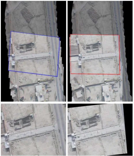
Areas to be surveyed by UAVs are, e.g., bridges, access points to enclosed areas, or traffic lanes. By repeated overflights, such an area can be observed with respect to changes of, e.g., recently parked vehicles. For our example sceneaccess point, Figure 1 shows video mosaics of two overflights using a linear flight path and Nadir viewing geometry.
Figure 1: Video mosaics of the example sceneaccess point: Pre-vious overflight with selected frame (blue, left) corresponding to the new frame (red, right) in the current overflight. 2nd row: Cur-rent frame (right) aligned to the previous frame (left).
We propose the surveillance task to be solved by using a work-flow consisting of the following steps:
Previous flight mission: Initially, a UAV mission is performed and a video mosaic is created covering the scene area to be surveilled. This video mosaic is geo-coded und serves as refer-ence for the following steps. It is shown in Figure 1 as darkened background both on the left and on the right of the 1st row.
Current flight mission: For the current point in time, another UAV mission is performed by acquiring the video imagery in the same manner as in the previous mission, i.e. by visiting the same way points and by using the same Nadir viewing geometry.
Video frame selection: For each new video frame of the current flight mission, a corresponding video frame of the previous flight is selected due to a maximum overlap of the imaged scene in both frames. By this, a sequence of image pairs is created consisting of the frames of the current overflight together with each selected frame from the previous overflight.
Frame alignment: For each video frame pair, an automatic image-to-image registration is performed using a robust match-ing approach. By the estimated homography, the current frame is aligned to the previous frame (Fig. 1, 2nd row).
Change detection between single images: The aligned image pair is the input for the change detection algorithms described in
section 3. The resulting change mask is an attribute image given in the same pixel raster as the aligned input image pair.
Co-locating the change masks: The frames of the previous flight are attached to the geo-coded reference video mosaic by using the transformations from the mosaicking process (1st step). The frame alignment (4th step) delivers an attachment of each current frame and of each change mask to the reference mosaic. These attachments align the frames to the mosaic in the 1st row of Figure 1, where each previous and each current frame is subse-quently overlaid on the reference mosaic (darkened background). By this, the reference mosaic is updated to become an aligned “current” video mosaic.
Temporal change mask filtering:During the current flight, the frame pairs and the co-located change masks are sweeping over the reference video mosaic. Each pixel is visited for several times and the occurrences of change attribute values are accumulated and filtered. This procedere is described in section 4.
The final result is an overall change mask aligned to the reference video mosaic. Further exploitation can for example be performed by a human image interpreter using a suitable visualization of the detected changes.
3. ALGORITHMS FOR DETECTING CHANGES
Change detection methods are based on the comparison of two aligned images. Initially, we discuss the main challenges when suppressing image changes which come from image and scene changes considered not to be relevant for the specific task.
Radiometric changes due to illumination and reflection:Due to different day time or changed atmospheric conditions, object surfaces, shadows, and background can differ substantially in the images. Appropriate measures to suppress these effects consist in applying suitable pre-processing steps and in using methods which are invariant or less sensitive to offset and scaling of image intensity and contrast.
Geometric distortions and displacements:Objects of the scene are displaced due to 3D parallax caused by different positions of the sensor at the time of image acquisition. The displacements are usually not larger than only a few pixels and they are mixed with other effects such as lens distortion or compression artifacts. Therefore, the displacements are difficult to be used for struc-ture from motion algorithms. They are considered as noise and have to be suppressed by appropriate algorithms, e.g., by using a neighborhood for searching pixels with minimum absolute dif-ferences. This approach is based on a non-symmetrical distance measure which is common in the context of document analysis (Ges`u and Starovoitov, 1999) and (Baudrier et al., 2008). Appli-cation to background subtraction is used in (Pollard and Antone, 2012) while (Saur and Kr¨uger, 2012) and (Saur et al., 2014) are applying it for detecting changes in video image pairs.
Noise and artifacts: Contributions come from intensity noise and compression artifacts but also from other effects, that are con-sidered as noise, e.g., small changes such as shadows and occlu-sions, or the above mentioned effects of illumination changes and local displacements. Noise handling is an important step since image differencing is decreasing the signal-to-noise ratio. Meth-ods to suppress noise may consist for example of spatial filtering and also of temporal filtering when using video sequences since the same changes can be observed in many video image pairs (see section 4).
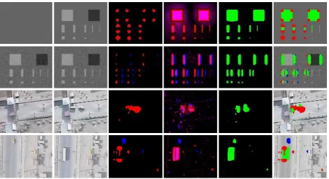
Figure 2: Change detection examples (1st-4th row): Previous image (1st column), current image (2nd column), masks of feature based approach (3rd), extended image differences using a7×7neighborhood (4th), differencing mask (5th), and combined mask over current gray image (6th column). 1st row: Constant gray image and synthetic test image containing rectangles and squares of width 1, 2, 4, 6, and 8 pixels. 2nd row: Two copies of the test image with added noise and left-shifted by 8 pixels. 3rd and 4th row: subframes of aligned video frames. The colors red and blue in the 3rd, 4th and 6th column correspond to structures present in the current and previous image and indicate new or vanished objects. Magenta in the 4th and green in the 5th and 6th column denote changed object areas.
3.1 Extended image differencing
We now revisit the approach of extended image differencing from (Saur et al., 2014). Denoting byI1=I1(x)andI2=I2(x)with
pixelsx= (x, y)the equal-sized gray scale images of the scene, the imageD = D(x)of the absolute differences is derived by pixelwise differencing
D(x) =|I1(x)−I2(x)|. (1)
To reduce the effects of changing illumination and shading, a lo-cal adaption of the intensities is performed by adding the low pass filtered difference image toI1and replacingI1byˆI1with
ˆI1= I1+ (I2−I1) = I1+ (I2−I1). (2)
Extended image differencing is based on a minimum search in a local neighborhood windowN. Depending on in which image the neighborhood search is applied, we get the difference images
DI1(x) = min
∆x∈N|I1(x)−I2(x+ ∆x)|, (3) DI2(x) = min
∆x∈N|I
2(x)−I1(x+ ∆x)|. (4)
Since the search result is not symmetric w.r.t. toI1 andI2, i.e.
DI1(x)̸=DI2(x), we introduceDI(x)which is symmetric:
DI(x) = max(DI1(x), DI2(x)) (5)
Finally the change maskMI(x)is derived fromDI(x)using an adaptive threshold to eliminate thin structures.
Figure 2 shows four examples where each previous imageI2 is
placed in the 1th column and each current imageI1in the 2nd.
Using a7×7neighborhood forN, the resultingDI1(red) and
DI2(blue) are shown in the 4th and the change maskMI(green)
in the 5th column. Applied to a synthetic test image and constant gray image (1st row), we see, that the neighborhood search pre-serves the small structures of even 1 and 2 pixels width. In the mask imageMI, the 1-pixel structures are eliminated.
In the 2nd example two copies of the test image are shifted to each other and noise is added. Using a7×7neighborhood, all shifts lower than 4 pixels are suppressed by construction andDI1,DI2
and MI are constant black. Due to thresholding, MI remains black for shifts up to 6 pixels. We show here an example with a shift of 8 pixels (2nd row). The shifts on both sides of the boxes are detected,I1on the left (red) andI2on the right (blue). InMI
the 2-pixel structures are eliminated.
In the examples with real sensor images (3rd and 4th row),I1and
I2 indicate the vehicles including their shadow by magenta (red
and blue) and smaller objects (persons and two-wheelers with shadows) are indicated distinct in red or blue. InMI, the smaller and lighter ones are filtered out.
3.2 Feature-based approach
A new feature-based change detection method for image pairs is introduced to complement change detection by extended image differences. The idea is to find changes by comparing suitable local image features between the two input images. The method computes two directed binary change masksC12andC21. Mask
C12marks locations, where salient image structure is present in
the first image, but is missing in the second image. MaskC21
compared. Although the two change masks can be combined into a single undirected change mask, keeping them separately has the advantage of preserving the type of change hinted at.
The first step of the proposed change detection method is to com-pute feature strength mapsF1(x)andF2(x)for the two input
imagesI1(x)andI2(x). The method then uses two thresholds,
t0andtr, to compute the directed change masksC12andC21:
C12(x) = (F1(x)> t0 ∧ F1(x)> trF2(x)) (6)
C21(x) = (F2(x)> t0 ∧ F2(x)> trF1(x)). (7)
Thresholdt0is an absolute threshold used to detect presence of
sufficiently strong local features. Thresholdtris a relative thresh-old which is used to compare the relative feature strength between the two images.
Our measure of feature strength is based on the second-moment matrix of the image gradient(Ix, Iy)T, also called structure ten-sor (J¨ahne, 1993). Denoting the mean value of an image function Gin a local window centered on positionxbyG(x), the2×2 second-moment matrixM(x)is given by
M(x) =
The eigenvaluesλ1 and λ2 of M(x) distinguish three classes
of local image structure atx: corner (λ1 > 0, λ2 > 0), edge
(λ1 >0,λ2 = 0), and homogeneous patch (λ1 = 0,λ2 = 0).
Corner detection (F¨orstner and G¨ulch, 1987), (Shi and Tomasi, 1994) is often based on the second-moment matrix of the image gradient. Here, we use the determinant of the second-moment matrix to compute the feature strength for imageIat positionx:
F(x) =Ix(x)Ix(x)Iy(x)Iy(x)−Ix(x)Iy(x)Ix(x)Iy(x).
This definition of feature strength emphasizes corners and has shown to provide good experimental results for the type of objects (small vehicles, persons) we are interested in.
Optionally, morphological opening with a small rectangular structuring element is used as a post-processing step to remove small isolated regions from the change masks.
Both directed change masks of the feature based approach are shown in the 3rd column of Figure 2 using red color forC12and
blue forC21. Only the corners of the boxes are indicated since
inside the objects and at straight border edge lines the feature strength is low. In the 1st and 2nd row, the 1- and 2-pixel ob-jects are suppressed. Using a shift of 8 pixels, new and vanished corners are indicated, while shifts of up to 6 pixels yield black im-ages forC12andC21. In the real images, all changed vehicles are
marked and merged with their shadow. The bus is indicated by two separate blobs. Some smaller changes are indicated as well and distinctly separated into new and vanished objects. Mixed attributes (magenta) do not occur per construction.
3.3 Combining the results of both approaches
One obvious method to combine the approaches consists in merg-ing the change masks. In the last column of Figure 2, the current gray image is overlaid by the green extended image differences MIand thereafter overlaid by the redC12and blueC21coming
from the feature based approach. Both results are comparable with respect to the sensitivity to object size and object shift.
We now can observe the following effects:
Indicating the changes: In all examples, both approaches in-dicate the large and salient changes. The sensitivity to smaller changes is different for both depending on their feature strength and their intensity difference compared to the background.
Indicating the object shape: The feature based approach indi-cates the corners of an object while the green extended image differencing mask fills out its interior. Both together mark the complete obejct shape including its shadow.
Directed change mask: The feature based approach distinctly discriminates between new and vanished objects, while the sep-aration by extended image differencing is less clear (DI1 and
DI2). Therefore the greenMIis suitable for undirected changes.
We suggest the following rules for combining the approaches:
1. Green and red blobs having a certain overlap are aggregated and the color red is assigned to the aggregations,
2. Overlapping green and blue blobs are aggregated in the same way and the color blue is assigned,
3. Overlapping aggregates are merged and get their common color or green otherwise,
4. Isolated small blobs are suppressed.
The colors are assigned to the change attributes with red for “new object” and blue for “vanished object”, while green indicates undirected changes and is associated with “changed object area”.
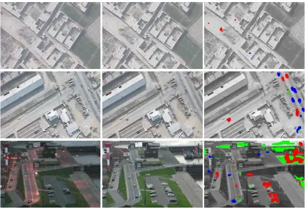
For analyzing and comparing the results of both approaches how-ever it is more convenient to visualize them without aggrega-tion and suppression. In Figures 3 and 4 the results have the same color coding and are produced with the same parameters as those in Figure 2, 6th column. Figure 3 shows three exam-ples using subframes of aligned UAV video images (1st and 2nd row) and from a fixed sensor position using oblique view (3rd row). All changed vehicles and smaller objects are assigned as expected from the input. The images of the harbor scene (3rd row) are taken at different daylight time and the blobs mark addi-tional spotlights and areas with changed surface and illumination (street, water).
4. APPLICATION TO VIDEO IMAGE SEQUENCES
An obvious approach to video change detection consists in adopt-ing remote sensadopt-ing methods to video exploitation: From repeated overflights over the scene, geo-coded video mosaics are created, to which single image pair change detection is applied. Using video mosaics has the advantage that they represent compact im-age coverings of the scene and that few mosaics are easier to han-dle than hundreds of video frames. This is an important aspect for a semi-automatic workflow, where human image interpreters are involved.
On the other hand, video mosaics are composed of many slim strips coming from different video frames acquired at different points in time and from different sensor positions with differ-ent attitudes. This causes artifacts at non-stationary scenes, e.g., moving cars get a longer or shorter image representation depend-ing on whether they are movdepend-ing in the same or in the opposite direction compared to the sensor footprint’s movement. Since the viewing geometry differs from slice to slice, the 3D structures of the scene get mapped differently and therefore cause additional The International Archives of the Photogrammetry, Remote Sensing and Spatial Information Sciences, Volume XLI-B7, 2016
Figure 3: Change detection results for urban scenes in Nadir view from UAV (1st and 2nd row) and from a fixed sensor position in oblique view at different daylight time (3rd row): Subframes of registered originals (1st and 2nd column) and combined change masks (3rd column) over input gray image using the same color coding as in Figure 2.
distortions in the mosaic. Finally, these distortions may increase during the mosaicking process due to error propagation.
In order to cope with small distortions, (Saur et al., 2014) intro-duced an approach using an elastic transformation based on thin splines for aligning the video mosaics.
For sustainably eliminating larger distortions due to 3D effects, these errors must be suppressed already during the mosaicking process. A common approach consists in modelling the mapping and the 3D structure of the scene and thus creating so called true ortho-images from the video frames and stitching them together to get true ortho-mosaics. Comparing the true ortho-mosaics of the previous and of the current flight, the 3D problems have been eliminated in the case that the additionally needed 3D models are accurate enough. This approach however is very complex, especially when trying to perform the change detection in real time during the video acquisition of the current flight. And the problems with moving objects are still remaining.
In this paper however, we suggest an approach based on the video mosaic of the previous flight and on subsequently applying change detection to single video frame pairs within the workflow described in section 2:
Creating a video mosaic of the previous flight:The video mo-saic serves as 2D reference for both the previous and the current video frames. Its creation is independent from the current flight and therefore it needs not to satisfy realtime requirements with respect to the current flight. In Figure 4, the video mosaic serves as background image.
Change detection between previous and current frames:The change detection is performed by the algorithms described in
sec-tion 3. In Figure 4, for three points in time the overlapping area of the previous and the current video frame is darkened and overlaid onto the background. Then, the colored change mask is overlaid onto the overlapping area.
Derivation of the reference change mask: The change masks from the frame pairs are aligned to the mosaic and therefore, for each pixel of the reference mosaic, the occurrences of frame cov-erings and of each change attribute can be accumulated. The final change mask attached to the reference mosaic is derived from the relative frequencies of the change mask attributes, e.g., by adap-tive thresholding and morphological filtering to suppress small changes. In Figure 4, the reference change mask is overlaid over the background reference image where the pixels already have been visited by the sweeping frames. In our example, we applied the fixed thresholds 0.5 and 0.8 to the relative frequency of the new and vanished objects (red and blue) in order to distinguish between more and less significant changes (light red/light blue).
Compared to using aligned mosaics for change detection as de-scribed in (Saur et al., 2014), we observe the following benefits:
• The change detection works on the original sensor images and has not to deal with distortions of the mosaics.
• Deriving the reference change mask from the relative fre-quency corresponds to a temporal filtering of the detected changes. Thus, less frequently detected changes at a certain pixel are suppressed due to their lower significance.
Figure 4: Change detection results for the overflights over the sceneaccess pointfrom Fig. 1: Changes between previous and current video frame for three different points in time (left, center, and right image) with the overlapping area of current and previous video frame (darkened) and the reference video mosaic as background. In the progress of time, the overlapping area sweeps from the bottom to the top and the mosaic gets updated by the overlapping area and by the reference change mask “behind” it. The change mask colors correspond to Figure 2. The additional colors light blue and light red in the reference change mask indicate less significant changes.
• Since change detection between image pairs is not restricted to Nadir viewing geometry (e.g., see 3rd row in Figure 3), this approach can be extended to overflights with off-Nadir viewing geometry by using an appropriate reference image.
Additionally, as shown for the different points in time in Fig-ure 4, the video change detection can be implemented as process following each new frame of the current overflight. Thus, in a semi-automatic workflow, for each new frame, the visualization of Figure 4 gets updated. A human image interpreter can observe the overlaid change mask in the progress of time and may decide which of the indicated changes are relevant for his task.
5. CONCLUSIONS AND FUTURE WORK
We presented (1) a new feature based approach for detecting changes in aligned image pairs, we (2) combined it with our pre-vious approach based on extended image differencing (Saur et al., 2014), and we (3) introduced a method for its application to video image sequences. Several examples, using repeated UAV video overflights over a scene, show the benefit of the approach com-pared to (Saur et al., 2014). Additionally, an attributed change mask is created by distinguishing new objects from vanished ob-jects and changed obob-jects areas.
The main drawbacks of the approach lie in the missing modelling of moving objects and of the 3D structures of the scene. How far the application is limited to near-Nadir viewing geometry can be explored e.g. by using simulation (Saur and Bartelsen, 2015).
In a further step we plan to separate the changes caused by mov-ing objects from changed static objects by integratmov-ing a compo-nent for motion detection and tracking. Further extensions of the algorithms would be considering other types of features such as texture or incorporating an available 3D model of the scene.
REFERENCES
Baudrier, E., Girard, N. and Ogier, J.-M., 2008. A non-symmetrical method of image local-difference comparison for
ancient impressions dating. In: Graphics Recognition. Recent Advances and New Opportunities, Lecture Notes in Computer Science, Vol. 5046, Springer Berlin Heidelberg, pp. 257–265.
F¨orstner, W. and G¨ulch, E., 1987. A fast operator for detection and precise location of distict point, corners and centres of circu-lar features. In: Proceedings of the ISPRS Conference on Fast Processing of Photogrammetric Data, pp. 281–305.
Ges`u, V. D. and Starovoitov, V., 1999. Distance-based functions for image comparison. Pattern Recognition Letters 20(2), pp. 207 – 214.
J¨ahne, B., 1993. Spatio-Temporal Image Processing: Theory and Scientific Applications. Lecture Notes in Computer Science, Vol. 751, Springer.
Lu, D., Mausel, P., Brond´ızio, E. and Moran, E., 2004. Change detection techniques. International Journal of Remote Sensing 25(12), pp. 2365–2401.
Pollard, T. and Antone, M., 2012. Detecting and tracking all mov-ing objects in wide-area aerial video. In: Computer Vision and Pattern Recognition Workshops (CVPRW), 2012 IEEE Computer Society Conference on, pp. 15–22.
Radke, R. J., Andra, S., Al-Kofahi, O. and Roysam, B., 2005. Image change detection algorithms: A systematic survey. IEEE Transactions on Image Processing 14, pp. 294–307.
Saur, G. and Bartelsen, J., 2015. Experimental application of simulation tools for evaluating UAV video change detection. In: Proc. SPIE, Vol. 9653, pp. 96530P–96530P–7.
Saur, G. and Kr¨uger, W., 2012. Short-term change detection for UAV video. In: Proc. SPIE, Vol. 8537, pp. 85370R–85370R–11.
Saur, G., Kr¨uger, W. and Schumann, A., 2014. Extended im-age differencing for change detection in UAV video mosaics. In: Proc. SPIE, Vol. 9026, pp. 90260L–90260L–10.
Shi, J. and Tomasi, C., 1994. Good features to track. In: IEEE CVPR, pp. 593–600.