ENHANCED RGB-D MAPPING METHOD FOR DETAILED 3D MODELING OF LARGE
INDOOR ENVIRONMENTS
Shengjun Tangade, Qing Zhuabcd, Wu Chene, Walid Darwishe, Bo Wue, Han Hue, Min Chenc
aState Key Laboratory of Information Engineering in Surveying Mapping and Remote Sensing, Wuhan University, 129 Luoyu Road, Wuhan, Hubei, China –[email protected]
bState-Province Joint Engineering Laboratory of Spatial Information Technology for High Speed Railway Safety, Chengdu, Sichuan, China
cFaculty of Geosciences and Environmental Engineering of Southwest Jiaotong University, Chengdu, Sichuan, China – [email protected], [email protected]
dCollaborative Innovation Center for Geospatial Technology, 129 Luoyu Road, Wuhan, Hubei, China
eDepartment of Land Surveying & Geo-Informatics, The Hong Kong Polytechnic University, Hung Hom, Kowloon, Hong Kong – [email protected], [email protected], [email protected], [email protected]
Commission I, ICWG I/Va
KEY WORDS: Indoor Modeling, RGB-D Camera, Depth, Image, Camera Pose, Registration
ABSTRACT:
RGB-D sensors are novel sensing systems that capture RGB images along with pixel-wise depth information. Although they are widely used in various applications, RGB-D sensors have significant drawbacks with respect to 3D dense mapping of indoor environments. First, they only allow a measurement range with a limited distance (e.g., within 3 m) and a limited field of view. Second, the error of the depth measurement increases with increasing distance to the sensor. In this paper, we propose an enhanced RGB-D mapping method for detailed 3D modeling of large indoor environments by combining RGB image-based modeling and depth-based modeling. The scale ambiguity problem during the pose estimation with RGB image sequences can be resolved by integrating the information from the depth and visual information provided by the proposed system. A robust rigid-transformation recovery method is developed to register the RGB image-based and depth-based 3D models together. The proposed method is examined with two datasets collected in indoor environments for which the experimental results demonstrate the feasibility and robustness of the proposed method.
1. INTRODUCTION
Detailed 3D modeling of indoor environments is an important technology for many applications, such as indoor mapping, indoor positioning and navigation, and semantic mapping (Henry et al., 2014). Traditionally, there are two main approaches to indoor 3D modeling, terrestrial laser scanning (TLS) and close-range photogrammetry. With TLS technology, the obtained 3D point clouds contain detailed structure information and are well suited for frame-to-frame alignment. However, TLS lacks valuable visual information that is contained in color images. Although color images are easily captured with off-the-shelf digital cameras and the rich visual information can be used for loop closure detection (Konolige and Agrawal, 2008; Nistér, 2004), it is hard to obtain enough points for dense modeling through regular photogrammetric techniques, especially in dark environments or poorly textured areas (Henry et al., 2010; Kerl et al., 2013; Triggs et al., 2000).
Recently, the advent of RGB-D sensors such as the Kinect and Structure Sensor has led to great progress in dense mapping and simultaneous localization and mapping (SLAM) (Dryanovski et al., 2013; Hu et al., 2012; Whelan et al., 2013, 2015). The remarkable advantages of these systems are their high mobility and low cost. However, RGB-D sensors have some significant drawbacks with respect to dense 3D mapping. They only allow a measurement range with a limited distance
* Corresponding author: Shengjun Tang
and a limited field of view. They may cause tracking loss due to the lack of spatial structure needed to constrain ICP (iterative closest point) alignments (Henry et al., 2014). In particular, as the random error of the measurement depth increases with increasing distance to the sensor, only the data acquired within a 1-3 m distance to the sensor can be used for mapping applications (Khoshelham and Elberink, 2012). The RGB-D sensors capture RGB images along with per-pixel depth images, which enables the estimation of the camera poses and the scene geometry with an image-based algorithm, such as SLAM or structure-from-motion (SFM). Although the 3D scenes recovered from the RGB image sequences have a larger and longer range than the 3D model from the depth sensor, the motion between frames can only be recovered up to a scale factor, and the error of the motion can accumulate over time during frame-to-frame estimation (Kerl et al., 2013; Wu et al., 2014). The RGB image-based and depth-based methods for 3D modeling have their own advantages and disadvantages, but a more fundamental solution is desired to enhance the ability of the RGB-D sensors for indoor mapping (Steinbrucker and Kerl, 2013).
This paper is organized as follows. In Section 2, we briefly review related approaches. In Section 3.1, we describe the calibration methodology for both the RGB camera and infrared (IR) camera. In the Section 3.2, we give a general description of the device components and working mechanism of the RGB-D system. The procedure involved in our enhanced RGB-D mapping approach is also briefly introduced. Section 3.3 presents the relative pose estimation method from color image sequences. Section 3.4 describes the robust registration method to recover the rigid transformation relationship between the camera pose from SFM and from the ICP depth alignment algorithm. Section 4 presents the expanded results obtained with the enhanced mapping method, and we close with our conclusions in Section 5.
2. LITERATURE REVIEW
Due to the limitations in the measurement distance and accuracy of the RGB-D sensors, most of the research work in the past concentrated on alignment methods for depth frames to produce a 3D scene.
Newcombe et al. (2011) proposed the KinectFusion method, which incrementally registers RGB-D frames. As it also accumulates drift during the mapping procedure, the KinectFusion is applied in small workspace mapping (Newcombe et al., 2011). Henry et al. (2012) proposed a method to incorporate visual information into the ICP algorithm for image registration, called RGB-ICP. It is fascinating to see that the RGB-ICP method can improve the alignment accuracy to a certain extent. However, the final models in their two experiments were still broken and lacked abundant details in unmeasured spaces. The authors suggested that it would be favorable to apply a visualization technique such as PMVS (patch-based multi-view stereo) to enrich the indoor model (Henry et al., 2012). Endres et al. (2014) accomplished similar work. They used RANSAC (random sample consensus) to estimate the transformations between associated key points and then generate a volumetric 3D map of the environment (Endres et al., 2014). They mainly concentrated on SLAM instead of scene modeling. Stuckler and Behnke (2012) presented an approach for scene modeling and pose tracking using RGB-D cameras. Only two experiments in a small range were conducted to evaluate the performance of the registration (Stuckler and Behnke, 2012). Although the improvement of depth alignment can enlarge the modeling range of the sensor significantly, the absolute distance limitation may cause trouble when modeling a large-scale indoor scene with a high arched roof such as in airport terminals or churches.
Khoshelham and Elberink (2012) presented an experimental analysis of the geometric quality of depth data acquired by the Kinect sensor (a typical RGB-D system), and the results of their experiments showed that only the data obtained within a 1-3 m distance to the sensor can be used for mapping applications. The depth resolution also decreases quadratically with increasing distance from the sensor. Meanwhile, the field of view of the sensor may also cause “details lost” such that these lost details may cause trouble that it is hardly found through all of the spaces when modeling a large-scale indoor environment. Instead, the corresponding color image sequences may provide
extra information for the unmeasured areas. The image-based modeling approaches can create 3D models from a collection of input images (Grzeszczuk 2002; Pollefeys et al., 2004; Snavely et al., 2006). In this paper, we used the SFM method to recover camera parameters and sparse 3D scene geometry (Hartley and Zisserman, 2003). PMVS2 was involved for dense 3D modeling (Furukawa and Ponce, 2010). Because the SFM procedure can only recover the motion between frames up to a scale factor, a precise global scale recovery method is required.
We introduce a robust registration method by combining color image sequences with depth information. The global scale of the pose from SFM can be recovered, and rigid transformation between the models from the two sources can be obtained for their automatic registration. The major contributions of this research are 1) the developed method can extend the modeling range of the RGB-D sensors and enrich the scene details by integrating depth information and image information; and 2) a robust registration method is developed to recover the scale and the rigid transformation between the camera pose from SFM and from depth alignment with the ICP algorithm.
3. ENHANCED RGB-D MAPPING FOR INDOOR
ENVIRONMENTS
3.1 Overview of the Enhanced RGB-D Mapping System
The RGB-D sensor system used in this research contains two sensors, an RGB camera and an IR sensor. The IR sensor is combined with an IR camera and an IR projector. This sensor system is highly mobile and can be attached to an iPad, iPhone, or other mobile instruments. It can capture 640x480 registered color images and depth images at 30 frames per second. Figure 1 shows its hardware structure. The lower panels of Figure 1 show an example frame observed with the RGB-D sensor. The white part in the depth image indicates that no depth information is measured due to the distance limitation or surface material.
RGB Camera IR Camera
IR Projector
Figure 1. (Top) The hardware scheme of the RGB-D sensor, (bottom left) the acquired depth image, and (bottom right) the
Calibration stage
RGB camera calibration
Depth camera calibration
Internal parameters for RGB camera
Internal parameters for depth camera
RGB image sequence Depth image
sequence
Image-based 3D modeling stage Image feature tracking and matching
Motion estimation
Rigid transformation recovery stage RGB image and depth
image matching
Scale recovery using Pau ta Norm
Rigid transformation recovery using Besl and RANSAC methods Dense 3D
modeling with PMVS
3D model from RGB image sequence
3D model from depth sensor
Combined 3D indoor model
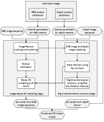
Figure 2. Flowchart of the enhanced RGB-D mapping approach
The proposed enhanced RGB-D mapping approach can be divided into three stages: the calibration stage, the image-based 3D modeling stage, and the rigid transformation recovery stage, as illustrated in Figure 2. First, an internal calibration method for both the RGB camera and the IR camera is conducted to obtain the intrinsic parameters of the cameras. Second, the SFM method is used for camera pose generation. Third, to register the 3D models from color image sequences to the models from depth information, a robust registration method is proposed by establishing the geometric relationship between them. An accurate global scale and rigid transformation can be obtained, which are used for absolute camera trajectory recovery. Finally, the absolute camera poses are used for dense 3D modeling with a PMVS tool, and the produced models are well matched with the 3D model from the depth sensor. The proposed method is examined using actual indoor datasets. The experimental results demonstrate the feasibility and effectiveness of the proposed method.
3.2 Camera Calibration
The main concept of camera calibration is based on the pinhole camera model, which illustrates the relationship between the image point and the corresponding ground point as a function of camera internal and external parameters.
The difference between the RGB camera and the depth camera is in the method of data collection. The RGB camera collects RGB images all the time. However, the data collected by the depth sensor depends on the status of the IR projector. When the IR projector switches on, the IR camera will collect the depth data for the scene, but if the IR projector is switched off, the IR camera will capture an ordinary image like the RGB image but on the IR band. The depth images on the IR band are used for the calibration progress. On the basis of the corresponding images, we apply the commonly used Bouguet (2011) method to calibrate the RGB camera and depth camera.
Finally, the focal length ( � ℎ, � ℎ) and the coordinate of the principal point ( � ℎ, � ℎ) of the IR camera are obtained. The internal parameters of the RGB camera are also calculated including the focal length ( ��, ��) and the coordinate of the principal point ( ��, ��). These are all used in the robust registration process detailed in Section 3.4.
3.3 Relative Motion Estimation
2000; Hartley and Zisserman, 2003; Snavely et al., 2006, 2008; Hu et al., 2015). Normally, two steps would be involved in the relative motion estimation: key-point detection and matching. In our work, we add an advance outlier rejection method to eliminate the false matches using the depth information and the pose derived from the ICP algorithm as a priori information. We summarize the steps in the motion estimation algorithm as follows.
3.3.1 Key-Point Detection and Matching: The SIFT detector (Lowe, 2004) is used for image feature detection. Typically, thousands of SIFT key points can be detected from each color image from an RGB-D sensor with 640*480 pixels. Based on the local descriptor of each key point, we use the approximate nearest neighbors package proposed by (Arya et al., 1998) for feature matching.
3.3.2 Camera Pose Estimation: We then robustly estimate a fundamental matrix between frames Fn-1 and Fn, and Fnand Fn+1, using the five-point algorithm (Nistér, 2004) and
RANSAC (Fischler and Bolles, 1981). Some outliers are removed with respect to the recovered fundamental matrix. It should be noted that not all of the RGB images need to be processed. Key frames are selected automatically based on the number of features tracked. Then, the rotation R and translation T are recovered by matrix factorization. This minimization problem is solved with the Levenberg-Marquardt nonlinear optimization (Nocedal and Wright, 2006), and then R and T are further refined.
3.4 Robust Registration of Depth-based and Image-based Models
Due to the nature of the RGB image-based method used for 3D modeling, we obtain the transformation relationship Tn,n+1 between the image pair {n, n+1} through relative motion estimation because the motion between frames can only be recovered up to a scale factor. The RGB image and the depth image are registered automatically by the sensor system itself, which facilitates the scaling and transformation of the relative model using the global distance from the depth images. The key step at this stage is to recover a global trajectory for the RGB image sequences by incorporating depth frames. First, the depth-based camera model is introduced below. Two kinds of coordinate systems, the camera coordinate system and the sensor coordinate system, are used. Then, scale and rigid transformation recovery are detailed.
3.4.1 Camera Model for Depth Images: The RGB-D camera uses the ICP algorithm for depth alignment. A relative camera pose for each frame can be obtained. By knowing the focal length � ℎ, � ℎ of the camera and the center of the depth image (� � ℎ, � ℎ), we can compute the object coordinates Xc, Yc, Zc, in the camera coordinate system as
follows:
= ℎ
� ℎ
− � ℎ
= ℎ
� ℎ
− � ℎ
= ℎ
The rigid body transformation that relates points
̃~[ ]� in the sensor coordinate system of the
referenced frame to points ̃~[� � � � ]� in the camera coordinates of the current frame can be written as
[ ] = [ � ] [ � �
�]
where R is the rotation matrix from current frame Fn to the referenced frame, t is the translation matrix from current frame Fn to the referenced frame, and X, Y, Z are the real object coordinates in the 3D scene.
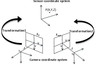
Figure 3 shows the relationship between the camera and sensor coordinate systems.
Fn Fn+1
P(X,Y,Z)
s1
s2
-f -f
u v
u
v
Transformation1 Transformation2
Sensor coordinate system
Camera coordinate system
Figure 3. The relationship between the camera and sensor coordinate systems
3.4.2 Scale Recovery
Based on the feature matches on the visual RGB images, the object coordinates for each tie point can be obtained by space intersection using the image orientation parameters. In this work, we select the registered frame that possesses the most corresponding points between the RGB frame and the depth frame as a control. As shown in Figure 4, for each feature match located on the RGB image, the image coordinates can be obtained and the corresponding depth value can be extracted from the registered depth image. Those points with no depth value are discarded. The object coordinates of each point can be calculated from Equation (1).
Figure 4. (Left) Feature matches from an RGB image. (Right) Feature matches on the corresponding depth image
former is obtained from the space intersection of the visual images, and the latter from the depth images. Then, the relative scale S can be determined from the distance ratio between the points pairs of the two points sets Pm and Pnas follows:
=√ � − � + � − � + � − �
√ � − � + � − � + � − �
! =
For robustness, a large number of scale ratios for point pairs is calculated at random, and three scale sets can be obtained. In our experiment, over 8000 scale values are calculated for this relative scale estimation. The Pau ta Norm and RANSAC methods are used for outlier rejection as in Equation (4),
{| �− | > � � Then, the proper scale is determined by the mean value of the remaining scales. The point sets from the space intersection of the visual images are scaled to a new points set Psas follows:
[ ] = [
3.4.3 Rigid Transformation Recovery: After scale recovery, it is necessary to find the optimal rotation and translation between the two sets of corresponding 3D points so that they are aligned. We compute the rigid transformation matrix using Besl’s method (Besl and McKay, 1992). The solution can be used for a dataset of any size as long as there are at least three
In particular, a RANSAC iteration is used for outlier rejection. An initial transformation matrix is calculated with all of the point pairs. The initial transformation is applied on the points set Ps, after which a new transformed points set PST can be
obtained, and the distance of each points pair in PST and Pncan
be calculated as in Equation (7).
� = √ ��− � + ��− � + ��− �
A criterion is set up to robustly filter out the outliers whenever the distance of points pair Dis is over Threshold (in our experiment, Threshold varied with the dataset used). Besl’s method is conducted iteratively until no outliers exist. Then, the proper rigid transformation matrix R1, t1between Ps and Pn is
recovered. The following equation relates the points set
̃~[ ]� in the world coordinate system to the 3D for the RGB camera, a scene view is formed by projecting 3D points into the image plane using a perspective lengths of the RGB image expressed in pixel units. (cxrgb, cyrgb) is the principal point that is usually at the image center. (Rr, tr) indicate the relative camera pose. It is convenient to combine equations (8) and (9) into one matrix equation as follows:
s [ ] = � [ ] [ � ] [ ] [ ] − [ ] feasibility and effectiveness of the proposed enhanced RGB-D mapping method. Two sets of data are collected using the structure sensor attached to an iPad Air. The camera calibration results are shown in Table 1.
IR sensor Focal length (pixels)
fxdepth 580±3.49
Principal point (pixels)
cxdepth 331.59±1.57
cydepth 236.59±1.98
RGB sensor
Focal length (pixels)
fxrgb 570.63±3.43
fyrgb 570.96±3.20
Principal point (pixels)
cxrgb 319.84±1.55
cyrgb 244.96±2.01
Table 1. Calibration results of IR camera and RGB camera
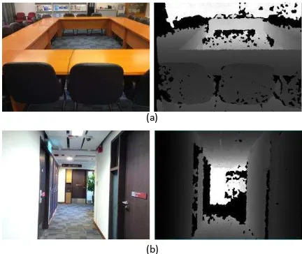
For the first dataset, a sample registered frame with the RGB image (left) and depth image (right) is shown in Figure 5(a). The white part in the depth image indicates that no depth value is measured due to the distance limitation or the type of surface material. This dataset contains 244 registered frames collected in a big meeting room. Because of the lack of shape structure, the IR view range is only set at 4.98*2.16*1.37 m to ensure uninterrupted tracking.
The second dataset was collected along a corridor. The whole length of the trajectory was about 26.5 m. It contains 305 registered frames. The two images in Figure 5(b) show the RGB frame (left) and depth frame (right).
(a)
(b)
Figure 5. (a) Sample images of the first dataset in a meeting room. (b) Sample images of the second dataset along a corridor
4.2 Experimental Results and Analysis
It should be noted that some color deviation may exist in the RGB images collected by the RGB-D sensor due to inaccurate perception of color in the indoor environment with the ever-changing light. Therefore, only the images without color deviation were used for pose estimation.
For the first experiment, all 244 RGB images were used for dense modeling due to the uniform source of light. For geometric registration, 266 feature points with valid depth information detected from the first RGB image were filtered out, and 1437 homonymous points within the view range were used as check points. They were extracted from the feature-matching results. The performance of the geometric registration was examined in object space. Table 2 lists the statistics of the discrepancies between the transformed point set and the point set from the depth image, including the Threshold, number of iterations, check points, and the RMSE in three directions. According to Table 2, the Threshold value was set at 0.1 due to the smooth surface of the meeting table.
As Table 2 shows, the registration accuracy was examined for each iteration. During the first iteration, all of the feature matches were used to recover the rigid transformation matrix. As expected, it generated the worst results because no outliers were rejected. The accuracy in the following two iterations generally remained unchanged. However, the accuracy in the Y and Z directions was significantly improved in the last iteration, in which the discrepancies were reduced from meter-level to centimeter-level in both the Y and Z directions. The models from the two sources were merged using the derived scale matrix and rigid transformation matrix. Figure 6(a) shows the model from the image sequences, which was produced from the 244 RGB images. In consideration of the tracking lost, the volume of the model was set to 4.98*2.16*1.37 m. The sensor system only selected a part of the depth information to model the scene. Figure 6(b) shows the model from the sensor. As expected, the image-based modeling approach achieved a larger measuring range. Registering of the latter to the former significantly enriched the details of the 3D scene
Dataset ID
Threshold (m)
Iteration times
Check points
Registration accuracy
AverageError-X(m) AverageError-Y(m) AverageError-Z(m)
1
0.1 1 1437 0.042 1.167 1.761
0.1 2 1437 0.033 1.174 1.770
0.1 3 1437 0.036 1.171 1.767
0.1 4 1437 0.037 0.040 0.030
2
0.03 1 1302 0.852 0.762 1.234
0.03 2 1302 0.321 0.435 0.865
Table 2. Statistics of discrepancies in object space
(a) (b)
(c)
Figure 6. Generated 3D models from the first dataset. (a) RGB image-based 3D model, (b) depth-based 3D model, and (c)
registered 3D model
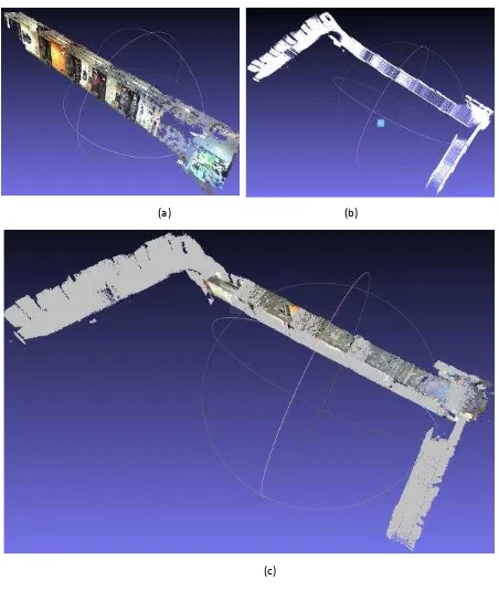
In the second experiment, due to the color deviation of some images, only 172 RGB frames with fairly accurate colors were used for dense 3D modeling. This involved 432 feature matches for geometric registration. Because of the distinguishing shape features, the Threshold value was set at 0.03. During the rigid transformation recovery process, the outliers were eliminated by comparing the registration accuracy with the threshold. Table 2 shows the accuracy of the registration. In the first iteration, all 432 feature points were used for transformation derivation. As there were some false matches, the obtained registration accuracy was about 1 m in the three directions. The outliers were rejected in the second iteration using the RANSAC method, and the discrepancy was reduced to 0.3, 0.4, and 0.8 in the X, Y, and Z directions, respectively. The last iteration achieved centimeter-level registration accuracy in all three directions. Figure 7 shows the scene from the image sequences, that from the sensor system, and the registered scene. As shown in Figure 7(a), the scene from the image sequences can cover only a part of the measured corridor because only some of the images were used in the SFM procedure. Figure 7(b) shows the obtained corridor model from the depth image. Although all of the depth information was merged together for model generation, significant details were lost, especially on the ceiling and the floor. The main reason for this may be the limited field of view of the IR sensor. The registered model is shown in Figure 7(c). The two models were matched well with the aid of the scale and transformation parameters. More importantly, the model obtained from the RGB images can be a good supplement to the model obtained from the sensor system. The structure information relating to the ceiling and the floor is enhanced by combining these two models.
(a) (b)
(c)
Figure 7. Generated 3D models from the second dataset. (a) RGB image-based 3D model, (b) depth-based 3D model, and (c)
registered 3D model
5. SUMMARY AND CONCLUSIONS
The key issues when using RGB-D sensors to produce 3D models are the limited measurement distance and the field of view. We have presented an enhanced RGB-D mapping scheme by combining RGB image sequences with depth information. This scheme aims to combine the model produced by the image sequences with the close detailed model to permit further and more detailed indoor modeling. The globle scale of the motion between RGB frames can be recovered by integrating the depth information and visual information provided by the system. Based on the robust registration method, the scaled camera motion is automatically transformed to the sensor-used coordinates system. Further experiments undertaken in the indoor environment to validate the feasibility and robustness of the proposed method show that it can automatically achieve accurate geometric registration between two models from different architectures. The loss of details with the sensor model can be well repaired by fusion with the model from the image sequences. Accordingly, the enhanced RGB-D mapping system can extend the measurement distance of the structure sensor system.
ACKNOWLEDGEMENTS
This research was funded by grants from the National Natural Science Foundation of China (Project No. 41501492) and the Hong Kong Research Grants Council (RGC) Competitive Earmarked Research Grant (PolyU 152023/14E).
REFERENCES
Arya, S., Mount, D.M., Netanyahu, N.S., 1998. An optimal algorithm for approximate nearest neighbor searching fixed dimensions. Journal of the ACM, 45(6): 891-923.
Besl, P.J., McKay, N.D., 1992. Method for registration of 3-D shapes. In Robotics-DL Tentative. International Society for Optics and Photonics, pp. 586-606.
Bouguet, J.-Y., 2011. Camera calibration toolbox for Matlab. Available at: http://www.vision.caltech.edu/, [Accessed 10 June 2015]
Chiuso, A., Favaro, P., Jin, H., Soatto, S., 2000. 3-D motion and structure from 2-D motion causally integrated over time: Implementation. Computer Vision—ECCV 2000, pp. 734-750.
Dryanovski, I., Valenti, R.G., Xiao, J., 2013. Fast visual odometry and mapping from RGB-D data. Robotics and Automation, pp. 2305-2310.
Endres, F., Hess, J., Sturm, J., Cremers, D., Burgard, W., 2014. 3-D mapping with an RGB-D camera. IEEE Transactions on Robotics, 30(1): 177-187.
Fischler, M.A., Bolles, R.C., 1981. Random sample consensus: a paradigm for model fitting with applications to image analysis and automated cartography. Communications of the ACM, 24(6): 381-395.
Furukawa, Y., Ponce, J., 2010. Accurate, dense, and robust multi-view stereopsis. IEEE Transactions on Pattern Analysis and Machine Intelligence, 32(8): 1362-1376.
Grzeszczuk, R., 2002. Course 44: Image-based modeling, In SIGGRAPH.
Hartley R., Zisserman A., 2003. Multiple view geometry in computer vision. Cambridge University Press.
Henry, P., Krainin, M., Herbst, E., Ren, X., Fox, D., 2012. RGB-D mapping: Using Kinect-style depth cameras for dense 3D modeling of indoor environments. The 12th International Symposium on Experimental Robotics.
Henry, P., Krainin, M., Herbst, E., Ren, X., Fox, D., 2014. RGB-D mapping: Using depth cameras for dense 3D modeling of indoor environments. Experimental Robotics, pp. 477-491.
Hu, H., Zhu, Q., Du, Z., Zhang, Y., Ding, Y., 2015. Reliable spatial relationship constrained feature point matching of oblique aerial images. Photogrammetric Engineering and Remote Sensing, 81(1): 49-58.
Kerl, C., Sturm, J., Cremers, D., 2013. Dense visual slam for RGB-D cameras. 2013 IEEE/RSJ International Conference on. IEEE, pp. 2100-2106.
Khoshelham, K., Elberink, S., 2012. Accuracy and resolution of Kinect depth data for indoor mapping applications. Sensors, 12(2): 1437-1454.
Konolige, K., Agrawal, M., 2008. FrameSLAM: From bundle adjustment to real-time visual mapping. Robotics, 24(5): 1066-1077.
Lowe, D.G., 2004. Distinctive image features from scale-invariant keypoints. International Journal of Computer Vision, 60(2): 91-110.
Newcombe, R.A., Izadi, S., Hilliges, O., 2011. KinectFusion: Real-time dense surface mapping and tracking. 10th IEEE International Symposium on Mixed and Augmented Reality (ISMAR), pp. 127-136.
Nistér, D., 2004. An efficient solution to the five-point relative pose problem. IEEE Transactions on Pattern Analysis and Machine Intelligence, 26: 756-777.
Nocedal, J., Wright, S., 2006. Numerical optimization. Springer Science & Business Media. Springer New York, pp. 245-269
Pollefeys, M., Van Gool, L., Vergauwen, M., Verbiest, F., Cornelis, K., Tops, J., Koch, R., 2004. Visual modeling with a hand-held camera. International Journal of Computer Vision, 59(3): 207-232.
Structure, 2015. Structure Sensor. [Online] Available at: http://structure.io/, [Accessed 27 July 2015].
Snavely, N., Seitz, S.M., Szeliski, R., 2006. Photo tourism: exploring photo collections in 3D. ACM Transactions on Graphics (TOG), pp. 835-846.
Snavely, N., Seitz, S.M., Szeliski, R., 2008. Modeling the world from internet photo collections. International Journal of Computer Vision, 80: 189-210.
Steinbrucker, F., Kerl, C., 2013. Large-scale multi-resolution surface reconstruction from RGB-D sequences. 2013 IEEE International Conference on Computer Vision, pp. 3264-3271.
Stuckler, J., Behnke, S., 2012. Integrating depth and color cues for dense multi-resolution scene mapping using RGB-D cameras. Proceedings of the IEEE International Conference on Multisensor Fusion and Integration for Intelligent Systems (MFI), pp. 162-167.
Triggs, B., McLauchlan, P.F., Hartley, R.I., Fitzgibbon, A.W., 2000. Vision Algorithms: Theory and Practice, Feature Based Methods for Structure and Motion Estimation. Springer-Verlag Berlin Heidelberg, pp. 278-294.