AUTOMATIC CAMERA CALIBRATION FOR CULTURAL HERITAGE
APPLICATIONS USING UNSTRUCTURED PLANAR OBJECTS
K. Adam*, I. Kalisperakis, L. Grammatikopoulos, G. Karras*, E. Petsa
Department of Surveying, Technological Educational Institute of Athens, Greece *Department of Surveying, National Technical University of Athens, Greece
[email protected], [email protected], [email protected], [email protected], [email protected]
KEY WORDS: Camera calibration, Point operator, Radial distortion, Bundle adjustment, Automation
ABSTRACT
As a rule, image-based documentation of cultural heritage relies today on ordinary digital cameras and commercial software. As such projects often involve researchers not familiar with photogrammetry, the question of camera calibration is important. Freely available open-source user-friendly software for automatic camera calibration, often based on simple 2D chess-board patterns, are an answer to the demand for simplicity and automation. However, such tools cannot respond to all requirements met in cultural heritage conserva-tion regarding possible imaging distances and focal lengths. Here we investigate the practical possibility of camera calibraconserva-tion from unknown planar objects, i.e. any planar surface with adequate texture; we have focused on the example of urban walls covered with graffiti. Images are connected pair-wise with inter-image homographies, which are estimated automatically through a RANSAC-based approach after extracting and matching interest points with the SIFT operator. All valid points are identified on all images on which they appear. Provided that the image set includes a ‘fronto-parallel’ view, inter-image homographies with this image are regarded as emulations of image-to-world homographies and allow computing initial estimates for the interior and exterior orientation elements. Following this initialization step, the estimates are introduced into a final self-calibrating bundle adjustment. Measures are taken to discard unsuitable images and verify object planarity. Results from practical experimentation indicate that this method may produce satisfactory results. The authors intend to incorporate the described approach into their freely available user-friendly software tool, which relies on chess-boards, to assist non-experts in their projects with image-based approaches.
1. INTRODUCTION
Recent CIPA symposia are witness to the importance of image-based digital documentation, including both reconstruction and visualization, of cultural heritage. In practice, all such projects rely today on un-calibrated (off-the-shelf) digital cameras. Their images are, usually, processed with some commercial software, handled more than often by experts in other fields – architects, engineers, archaeologists or conservationists – who may not be familiar with photogrammetry. Thus, it is not surprising that the issue of camera calibration has been gaining in significance (in practical close-range photogrammetric tasks camera calibration is essentially synonymous with camera pre-calibration). Several methods for camera calibration have been reviewed in literature (e.g. Clarke & Fryer, 1998; Salvi et al., 2002; Villa-Uriol et al., 2004; Zhang, 2004). The approaches differ regarding number of images involved; dimension (3D, 2D, 1D) of calibration objects used; adopted camera models; type of involved image features; linearity/non-linearity of employed algorithms, etc.
From a user’s point of view, cameras should ideally be calibra-ted in a totally automatic mode, exclusively from image sets of a possibly simple object acquired rapidly with unknown exterior orientations. A response to this demand is represented by freely available user-friendly tools for automatic camera calibration, which are usually based on structured 2D patterns (typically of the chess-board type); besides low cost and ease in construction, their contrast and pattern are particularly suitable for automatic feature extraction and, hence, establishment of point correspon-dences. Such tools, by exploiting different views of chess-board patterns to determine interior and exterior camera parameters, have been originally inspired by the “plane-based calibration” approach (Sturm & Maybank, 1999; Zhang, 1999), a process re-lying on the homographies between a world plane with known metric structure and its views. These 2D projective
transforma-tions give a linear system in the camera elements; the initializa-tion step thus yields a closed-form soluinitializa-tion for these parameters (lens distortion is generally not included). This step is typically followed by a non-linear refinement step (bundle adjustment).
Among such functional tools, the Camera Calibration Toolbox for Matlab® of J.-Y. Bouguet, also implemented in C++ and in-cluded in the Open Source Computer Vision library (distributed by Intel), is best known. We have also prepared the open-source free-access camera calibration toolbox FAUCCAL, which runs fully automatically as regards node extraction, establishment of image-to-pattern point correspondences and initialization, lead-ing to the final solution (Douskos et al., 2009). It may be added that Prokos et al. (2012) have reported on stereo-camera calibra-tion using ordinary chess-boards (one extra stereo pair of some scene is required to determine 2D epipolar geometry and exploit it for securing correct point correspondences).
initial estimates for the parameter values. Thus, algorithms have been developed for the estimation of camera parameters from the homographies between images of the same unknown 2D ob-ject. Since these inter-image homographies (collineations) are not independent, formulations have been reported for imposing geometric constraints in plane-based self-calibration to obtain reliable metric results from unknown 2D objects (Triggs, 1998; Malis & Cipolla, 2002; Menudet et al., 2008).
In this contribution we implement and investigate, in a practi-cable form, a version of ‘plane-based self-calibration’ which is performed directly by bundle adjustment. Walls covered with graffiti, which represent obvious choices of (practically) planar textured surfaces, have been used here. Images from the same camera are related pair-wise through inter-image homographies, established automatically (via a RANSAC-based approach) after interest points had been first extracted and matched by the SIFT operator. Points matched on any image pair are searched for on all images. The practical approach of Gurdjos & Sturm (2003) is employed, according to which one image should be (roughly) fronto-parallel against the planar object; therefore, inter-image homographies with this particular image may be seen as emula-tions of world-to-image homographies and allow closed-form approximations of the interior/exterior parameter values. Using the initial estimates for exterior orientation, images with unfa-vourable geometry are eliminated from the adjustment. Follow-ing this initialization step, estimates are introduced into a self-calibrating bundle adjustment. Solutions are constrained by en-forcing object planarity within a tolerance. No assumptions are made regarding fronto-parallelism (inter-images homographies are only used for fixing correspondences and for initialization).
Results from practical experimentation with different cameras indicate that (provided that ‘reasonable’ views have been used), this method leads to satisfactory results. In fact, the authors’ in-tention is to incorporate this approach into their freely available user-friendly software tool to assist non-experts in photogram-metry in projects in the field of cultural heritage documentation.
2. STEPS OF THE CALIBRATION ALGORITHM
2.1 Image acquisition
Image acquisition must involve significantly different and non-symmetric viewpoints of the scene; irregular geometric configu-rations greatly help towards reliable results (Sturm & Maybank, 1999). Triggs (1998) recommends an angular spread between cameras of at least 10–20°; referring to plane-based self-calibra-tion, he states that the addition of images significantly increases reliability and accuracy, up to a total of about 10. Since it is not always easy to exactly plan image acquisition, we suggest that more images be taken (e.g. 20). This precaution allows checking the overall geometric configuration and discarding with no pro-blem images which are similar to others. It is also recommended to include images with orthogonal roll angles which will loosen correlations between interior and exterior orientation elements. If a single camera is to be calibrated, focusing must remain con-stant. Finally, as already mentioned, one image (a ‘key frame’) should be taken as roughly fronto-parallel to the world plane to emulate a reference metric structure.
2.2 Inter-image homographies
The relation between two images x and x′ which depict a planar object is known as their inter-image 2D projective transforma-tion, or homography, which is an invertible transformation of 8
degrees of freedom represented by a 3×3 matrix:
.
Using homogeneous coordinates in the P2 space, the mathemati-cal expression of the homography becomes:
.
For computing the coefficients ≥4 point correspondences are re-quired. For fully automating the procedure, correspondences are fixed using the well-known SIFT operator (Lowe, 2004; see also http://www.cs.ubc.ca/~lowe/keypoints/). The algorithm extracts distinctive image features from scale invariant keypoints on the images to perform robust matching between extracted corners, yielding a set of point correspondences between the two images. However, the results from SIFT will contain false matches. For fitting the homography model with best accuracy by rejecting such matches, we use the well-known model-fitting algorithm RANSAC of Fischler & Bolles (1981). For each subset of four points (minimum number of points required for solution), H is computed and all points of the whole set which are consistent with the homograhy, within a given threshold, form the group of inliers. The group with the most inliers produces the final ho-mography matrix. The RANSAC algorithm has been used here as implemented by P. Kovesi (see cited website). Outcome of this step are point correspondences on all individual image pairs and the H matrices of the inter-image homographies which relate all available image pairs.
2.3 Final point correspondences
Point correspondences on image pairs have now to be identified on all possible images. All points involved in correspondences found on any image pair are thus investigated, and valid cor-responding points are accepted on all images on which they do exist. Whenever a conflict arises for some point (if it has been paired with different points on different images), all points in-volved are discarded. This procedure results in establishing on all images all possible point homologies which conform to the inter-image homographies. Finally, in order to strengthen the stability of the adjustment, only points appearing on ≥3 images are kept.
Even so, this step may produce very dense sets of image points. Therefore, they are decimated by defining a normal grid on each image and keeping only a specific number N of points in each cell (e.g. N = 1 if the grid is dense). If more points fall within a cell, selected are those N points which appear on more images. This allows choosing sufficient and possibly uniformly distribu-ted points.
2.4 Initialization
Besides point correspondences, a self-calibrating bundle adjust-ment requires initial values for the interior and exterior orienta-tion parameters. Regarding the first, and particularly the camera constant, the adjustment does not appear as being very sensitive to initial values. However, automatic initialization is possible.
co-nic, whose coefficients lead to the computation of the elements of interior orientation (Sturm & Maybank, 1999; Zhang, 1999). For obtaining initial estimates in the case of unstructured planar objects, Gurdjos & Sturm (2003) suggest use of a nearly fronto-parallel view, which in fact approximates the affine structure of the world (for unknown aspect ratio). Inter-image homographies which map the fronto-parallel image to each view are computed, and the following linear equation is used:
where is the ith column of H. For invariable camera constant, unknown principal point and aspect ratio, five inter-image ho-mographies are needed; coefficients , , , , are computed using Singular Value Decomposition. From them, the above camera parameters are determined. This solution ensures a linear computation of initial estimates of the interior orienta-tion parameters.
Assuming that the inter-image homographies between all other images and the fronto-parallel image approximate the view-to-world homographies, it is possible to compute estimates for the exterior orientation parameters using the camera constant value estimated above. Here this is done by adopting a parameteriza-tion attributed to Otto von Gruber (Bender, 1971), which allows estimating directly the remaining 8 interior and exterior orienta-tion parameters (principal point and exterior orientaorienta-tion) from these homographies. The solution provides the rotation angles a (azimuth), t (tilt) and s (swing). Two values emerge for angle s, one of which corresponds to positive imaging distance and pro-vides the correct estimates. A solution to this problem is given also in Sturm (2000).
Clearly, the estimated parameter values refer to a ‘world’ plane represented by the fronto-parallel image. Hence, the position of the projection centre is expressed in pixel dimensions; recon-struction of the object plane by the bundle adjustment will be in such a system.
2.5 Selection of images
When using all available images of the same planar object, it is not unexpected that a bundle adjustment may not converge. It is highly recommended to eliminate in advance images with very similar exterior orientation (to avoid small angles between inter-secting rays). The bases of all possible image pairs are projected onto the XY plane of the ‘world’ system (as defined above); if a base is smaller than a given fraction of the image diagonal, one of these two images is discarded. Alternatively, this may be ex-pressed as a threshold on base-to-distance ratio. Among images with similar exterior orientation, those having larger roll angles are retained. Finally, images with very small tilt (i.e. close to the fronto-parallel image) are also eliminated.
2.6 Bundle adjustment
Fixed point matches and initial estimates allow performing an iterative bundle adjustment, using the collinearity equations, to recover camera geometry. The adopted camera model involves the coefficients k1, k2 of symmetric radial lens distortion and the
aspect ratio a, along with the three primary camera parameters (camera constant c and principal point location xo, yo).
Since it is unknown “how planar” the object of each application actually is, the first solution does not include the planarity con-straint. Adjustment is performed by fixing 7 object space para-meters (the exterior orientation elements of the fronto-parallel
image and model scale). A plane is fitted to all reconstructed 3D points; a threshold may be then used to evaluate the RMS devia-tion of points from planarity. Based on practical experimenta-tion, an upper limit of 0.5% of the mean imaging distance was regarded here as realistic. If an assumed object plane fails the test, the results of the initial solution can be kept; however, they cannot be considered as entirely trustworthy since they have not been subject to any geometric constraint. On the other hand, if the object passes the test the adjustment is repeated with the in-troduction of a ‘soft’ constraint: coordinates Z = 0 of all object points are regarded as observations with large weight. The ulti-mate criterion, however, for accepting solutions based on plana-rity constraint is whether it strengthens the solution, in particu-lar the precision of camera constant estimation. The next section presents practical applications which include examples for all different cases referred to here.
3. PRACTICAL EVALUATION
Three different walls, assumed as being planar and covered with graffiti, have been recorded on four image sets (2 Mpixel). The sets include images of wide, normal and narrow fields of view.
•Image set 1. A total of 18 images have been taken, of which 5 were automatically excluded (see Section 2.5). The images used are shown in Fig. 1. Following Section 2.4, the initial value for the camera constant was 1079, namely quite close to the final value; principal point was estimated at the location xo = −10.6,
yo = −15.7, but (as in all cases) the principal point was initially
set at the image centre. The RMS error of plane-fitting to points produced by bundle adjustment was 0.24% of the mean imaging distance and hence regarded as satisfactory (see Sec. 2.6). The results in Table 1 show that the planarity constraint plays here no significant role; it simply causes an (expected) increase of the error σο of adjustment, which slightly raises the uncertainty of the estimated values. In general, the precision of camera geo-metry parameters is regarded as satisfactory. The standard error of the camera constant c, for instance, is 0.6‰.
Table 1. Calibration results for image set 1 (13 images, 941 object points)
without constraint with constraint
σο = 0.43 pixel σο = 0.51 pixel c (pixel) 998.25 ± 0.60 996.60 ± 0.63 xo (pixel) 0.10 ± 0.40 −2.05 ± 0.44 yo (pixel) −7.84 ± 0.32 −5.92 ± 0.35 (1−a) (×10−3) −0.19 ± 0.08 −0.60 ± 0.08
k1(×10−8) −8.63 ± 0.06 −8.58 ± 0.06
k2(×10−14) 4.64 ± 0.06 4.50 ± 0.06
•Image set 2. Here 11 images have been selected, seen in Fig. 2. The RMS error of plane-fitting to reconstructed points was very small (0.05% of the mean imaging distance). Calibration results of Table 2 show that here the planarity constraint plays a somewhat more significant role. Despite the increase of σο, the standard error of the camera constant c is improved (the other parameters exhibit a milder decrease in precision). In general, the precision of camera geometry elements is again satisfactory (the standard error of the camera constant c is 0.4‰).
Figure 2. Image set 2 (‘fronto-parallel’ is the first image).
Table 2. Calibration results for image set 2 (11 images, 754 object points)
without constraint with constraint
σο = 0.40 pixel σο = 0.47 pixel c (pixel) 2618.59 ± 1.23 2603.49 ± 1.09 xo (pixel) 24.07 ± 0.58 22.92 ± 0.64 yo (pixel) −8.99 ± 0.64 −6.23 ± 0.72 (1−a) (×10−3) −3.11 ± 0.08 −3.23 ± 0.09
k1(×10−9) −4.88 ± 0.42 −4.45 ± 0.46
k2(×10−15) 6.09 ± 0.40 4.36 ± 0.43
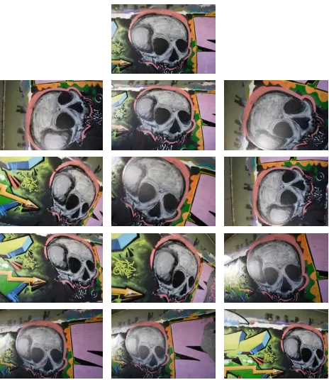
•Image set 3. The same pattern was imaged here, and 9 images were selected (Fig. 3). The RMS error of plane approximation was again small (0.11% of the mean imaging distance). In Table 3 the calibration results indicate that the imposed planarity has a significant effect. The standard error of the camera constant c is improved, while the other calibration parameters have the same precision. The overall precision is again satisfactory (standard
error of the camera constant c is less than 1.0‰).
Figure 3. Image set 3 (‘fronto-parallel’ is the first image).
Table 3. Calibration results for image set 3 (9 images, 632 object points)
without constraint with constraint
σο = 0.31 pixel σο = 0.35 pixel c (pixel) 1480.79 ± 1.67 1466.35 ± 1.42 xo (pixel) −3.45 ± 0.86 −2.17 ± 0.88 yo (pixel) −0.95 ± 0.91 −2.62 ± 0.88 (1−a) (×10−3) −0.14 ± 0.04 −0.13 ± 0.05
k1(×10−08) 1.79 ± 0.09 1.85 ± 0.08
k2(×10−14) −1.63 ± 0.12 −1.59 ± 0.12
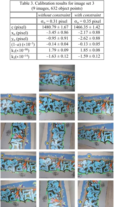
Figure 4. Image set 4 (the ‘fronto-parallel’ key frame is on top).
the object actually consists of two intersecting planes (Fig. 5).
Figure 5. Camera positions and reconstruction (image set 4).
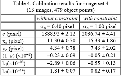
The calibration results in Table 4 show that when enforcing the planarity constraint the results, of course, deteriorate quite signi-ficantly. This stresses the importance of a planarity check. The solution without constraint is acceptable (standard error of the camera constant c is 1.1‰). Nonetheless, it is advisable to avoid such cases. Although it was here possible to get a solution, the fact that the pattern is non-planar (as assumed) results in invalid inter-image homographies; besides, it is generally expected that a large number of correct correspondences will be eliminated by the RANSAC algorithm. Probably this is the reason why in this case relatively few matched points have been retained.
Table 4. Calibration results for image set 4 (13 images, 479 object points)
without constraint with constraint
σο = 0.40 pixel σο = 1.00 pixel
In general, calibration results indicate that precise solutions are possible with this approach. Introduction of the planarity con-straint results in modifications, in some cases significant, of the estimated values of the parameters; it is assumed that the result-ing geometry is closer to the actual geometry of image acquisi-tion. Regarding parameter precision, the main effect of the geo-metric constraint is the reduction in all cases of the standard er-ror of the estimated camera constant.
A last observation concerns the correlation among estimates of the parameters. Partly owing to the strong roll angles, correla-tions between interior and exterior orientation parameters are generally weak. This is also true as regards correlations among interior orientation parameters. Exception is the correlation be-tween the estimates of coefficients k1 and k2 of radial distortion
(their correlation coefficient ranged between −0.86 and −0.92). Indeed, solutions only with coefficient k1 showed that,
practical-ly, it can fully describe radial distortion of the lenses used here.
4. CONCLUSION
Camera calibration, which is an indispensable intermediate step in several photogrammetric and computer vision tasks, may be conveniently performed in a fully automatic mode using various approaches. Perhaps the simplest among them is self-calibration based on recording unknown textured planar objects in several views. In this paper a practical implementation of this approach is presented. Points extracted and matched by the SIFT operator are filtered through inter-image homographies by employing the RANSAC algorithm. If a “fronto-parallel” image has been taken (after the suggestion of Gurdjos & Sturm, 2003), good estimates for interior and exterior orientation can be automatically found. These values allow discarding unsuitable images; they are then introduced into a bundle adjustment, in which all existing point matches participate. The reconstructed 3D points are tested for coplanarity to allow a final adjustment incorporating a planarity constraint. Satisfactory calibration results have been presented and discussed. The authors’ intention is to further elaborate this approach and incorporate it into their freely available software tool to assist non-experts in photogrammetry or computer vision in their projects in the field of cultural heritage documentation.
REFERENCES
Bender, L.U., 1971. Analytical Photogrammetry: A Collinear Theory. Final Technical Report RADC-TR-71-147, Rome Air De-velopment Center, New York.
Bouguet J.-Y., Camera Calibration Toolbox for Matlab: http://www.vision.caltech.edu/bouguetj/calib_doc/
Clarke T.A., FryerJ.G., 1998. The development of camera cali-bration methods and models. Photogrammetric Record, 16(91), pp. 51-66.
Douskos V., Grammatikopoulos L., Kalisperakis I., Karras G., Petsa E., 2009. FAUCCAL: an open source toolbox for fully au-tomatic camera calibration. XXII CIPA Symposium, October 11-15, Kyoto, Japan.
Fischler, Μ., Bolles, R., 1981. Random sample consensus: a pa-radigm for model fitting with applications to image analysis and automated cartography. Communications of the Association for Computing Machinery, 24(6), pp. 381-395.
Gurdjos P., Sturm P.F., 2003. Methods and geometry for plane-based self-calibration. IEEE International Conference on Computer Vision and Pattern Recognition, vol. 1, pp. 491–946.
Kovesi P., MATLAB and Octave Functions for Computer Vision and Image Processing
(http://www.csse.uwa.edu.au/~pk/research/matlabfns/)
Lowe D.G., 2004. Distinctive image features from scale-invari-ant keypoints. International Journal of Computer Vision, 60(2), pp. 91-110.
Malis E., Cipolla R., 2002. Camera self-calibration from unknown planar structures enforcing the multi-view constraints between collineations. IEEE Transactions on Pattern Analysis and Machine Intelligence, 24, pp. 1268–1272.
Prokos A., Kalisperakis I., Petsa E., Karras G., 2012. Automatic calibration of stereo-cameras using ordinary chess-board pat-terns. International Archives of the Photogrammetry, Remote Sensing and Spatial Information Sciences, vol. XXXVIII, Part 5, pp. 45-49.
Salvi J., Armangué X., Batlle J., 2002. A comparative review of camera calibrating methods with accuracy evaluation. Pattern Recognition, 35, pp. 1617-1635.
Sturm P.F., Maybank S.J., 1999. On plane-based camera cali-bration: a general algorithm, singularities, applications. IEEE Conference on Computer Vision & Pattern Recognition (CVPR ’99), Fort Collins, USA, pp. 432-37.
Sturm P., 2000. Algorithms for plane-based pose estimation. IEEE Conference on Computer Vision and Pattern Recognition, vol. 1, pp. 706 – 711.
Triggs B., 1998. Autocalibration from planar sequences. Euro-pean Conference on Computer Vision (EVVC ’98), vol. I, pp. 89-10.
Villa-Uriol M.-C., Chaudhary G., Kuester F., Hutchinson T. C., Bagherzadeh N., 2004. Extracting 3D from 2D: selection basis for camera calibration. IASTED Computer Graphics & Imaging, Kauai, USA, pp. 315-321.
Zhang Z., 1999. Flexible camera calibration by viewing a plane from unknown orientations. IEEE International Conference on Computer Vision (ICCV ’99), Corfu, pp. 666-673.