EFFECTIVE 3D DIGITIZATION OF ARCHAEOLOGICAL
ARTIFACTS FOR INTERACTIVE VIRTUAL MUSEUM
G. Tucci, D. Cini, A. Nobile
GeCo, Geomatics & Communication for Cultural Heritage Laboratory,
University of Florence, via Micheli 8, Florence, Italy
grazia.tucci@uni
fi
.it, daniela.cini@uni
fi
.it, alessia.nobile@uni
fi
.it
KEY WORDS: Cultural Heritage, Archaeology, Laser scanning, NextEngine®, Acquisition, Processing, Protocol, Virtual Museum
ABSTRACT:
This paper presents a set of results of an on-going research on digital 3D reproduction of medium and small size archaeological artifacts which is intended to support the elaboration of a virtual and interactive exhibition environment, and also to provide a scientifi c archive of highly accurate models for specialists. After a short illustration of the background project and its fi nalities, we present the data acquisition through triangulation-based laser scanning and the post-processing methods we used to face the challenge of obtaining a large number of reliable digital copies at reasonable costs and within a short time frame, giving an account of the most recurrent problematic issues of the established work-fl ow and how they were solved (the careful placing of the artifacts to be digitized so to achieve the best results, the cleaning operations in order to build a coherent single polygon mesh, how to deal with unavoidable missing parts or defected textures in the generated model, etc.).
1. INTRODUCTION
1.1 The MUS.INT. Project
Archaeological studies today employ three-dimensional models of
fi ndings and of sites in several study and communication phases (descriptive classification, morpho-typological comparative analyses, conservation, hypothetical reconstructions, scientifi c popularization, virtual museums, etc.), and therefore is highly required to fi nd adequate systems at a reasonable cost to generate digital models of series of fi ndings as per standard procedures. Our research team has been engaged for part of the past year in the 3D digital content production process within the MUS.INT. project “An interactive museum system design: The virtual museum of the Aegean and Cypriot antiquities collections in Tuscany”, funded by the Region of Tuscany, Italy, and coordinated by Prof. Anna Margherita Jasink of the Department of Antiquities of the University of Florence. The fi rst setting arranged within the project, launched in January 2010, aims to connect local archaeological collections of Aegean and East Mediterranean regions, fi rst of all the one held by the National Archaeological Museum in Florence, and share knowledge about artifacts stored in far apart museums and excluded from physical museographic events, in spite of their distinguished value in terms of quality and assortment of the repertoire, because affected by frequent space limitations. For the pilot virtual display 40 pieces have been selected: various kinds of ceramic pottery made on wheel, hand-modeled terracotta
fi gurines, and carved stone tools and objects from Early to Late Bronze Age wares (Figure 1). Decorated with painted, engraved or stamped geometric or naturalistic patterns, the fi ndings are illustrative of domestic and ceremonial craft techniques and forms manufactured in the Cycladic islands, Rhodes, Crete, Cyprus or imported by Greece (Mycenae) (for reference resources on the collections in Florence see Jasink and Bombardieri, 2009; Vagnetti et al., 2007; http://dbas.sciant.unifi .it/).
Various areas of expertise are involved in the implementation of the project, carried out under the scientifi c direction of the Dept. of Antiquities: besides archaeology for the content designing of the virtual exhibition, three-dimensional survey through range-based
Figure 1. Photos of a few holdings of the National Archaeological Museum in Florence,
which have been digitized Figurine of rider
on horse (Greece)
Bowl (Cyprus)
Phi-type fi gurine, legs missing (Greece)
Folded arms fi gurine (Cyclades)
Stirrup jar (Greece) Biconical collared
and image-based techniques, and multimedial communication to develop the interactive display platform and adapt the educational itineraries customized for distinct categories of users (specialists, students, families, etc.) to different interfaces (real time visualization on museum-based installations such as touch-screens, and on the Web).
The expectation is that in the oncoming future the same interactive system may house other kinds of exhibits formulated within renewable educational paradigms (e.g. guided vs. explorative).
1.2 Objectives of the research activity
Our task group, long experienced in laser scanning survey and geomatics, within the MUS.INT. project is providing for great part of the acquisition and 3D modeling of the fi nds to be displayed in the virtual museum and to be investigated by archaeologists and conservators in a status quo electronic fi ling system which will allow to examine scientifi cally the objects without any direct contact. Therefore, the diversity of purposes of the digitalized objects requires data versatility and separate processing procedures to prepare them for use. On one side, interaction on the Web and enjoyment of the virtual replicas demand as essential a photo-realistic reconstruction of the whole object and a convenient simplifi cation to decrease the size of data in order to be easily viewed; on the other, scholarly research and documentation call for as suitable and appropriate a very detailed description of the actual shape features with submillimetric precision, and contextually no
fi lling the gaps that may show up in the captured geometry (inside of vessels, hidden parts of handles, the rims’ underside in very rounded jars). Thus, our goal was to conceive a multiple data-base to satisfy all different intended uses, from high resolution source models not fi ltered by any mesh simplifi cation step and not subject to any replenishment action, to lower resolution “watertight” models utterly processed and sampled in defi nite proportions, to improve their rendering performance and storage costs depending on the application. Of course, as recommended by commonly shared general policies on ICT applications for Cultural Heritage (e.g., Arnold and Geser, 2008), also the distinctive target of the digital display needs to maintain a balance between engagement - entertainment objectives and analytical - educational approach, preserving at all times high fi delity to the real object.
Based on the large set of models and the variety of shapes and materials we have been dealing with, we could defi ne the most effective work-fl ows for data acquisition and processing, in order to fi x a standard and relevant guidelines to be followed easily also by non-specialized digital information providers and in other similar Cultural Heritage applications, not denying in certain phases a singular approach to each case, given the wide typological range that has been addressed. The most direct feedback of the usefulness of this additional documentation besides simply delivering output data for the project’s circumscribed target, will be in the ability to retrace the modeling process and in the fast training of other operators.
2. SURVEY AND DIGITAL REPRODUCTION METHODOLOGY
2.1 Scanning device
The 3D survey system we employed for the accurate and reliable virtual reproduction of the selected artifacts of the MUS.INT. project is NextEngine’s 3D Scanner HD, which falls into the triangulation-based laser scanners category. These are suitable for close-range applications and are generally used to survey medium and small objects, being the acquired area extent rather limited;
nevertheless it’s possible to combine and merge scans of several portions of bigger objects (as can be seen in Gallo et al., 2009). The size of the fi ndings of the current project ranges from 1 to 40 cm in height and/or width: according to the defi ned procedure policies, the bigger object to be laser scanned is ≈ 30 cm tall, while larger and heavier artifacts are being digitalized with the photogrammetric system Z-Scan by Menci Software (Tucci et al., 2010; Menci et al., 2007), partner in the project.
Triangulation laser-based 3D cameras detect the location of the point on the object shined by the laser beam in their own fi eld of view and measures it in their intrinsic space coordinates system, known the distance between camera and laser emitter (d, baseline), the angle of the emitter’s rotation (a), and the angle of the camera corner formed by the collected signal (b) (Figure 2).
The desktop 3D laser scanner produced by NextEngine Inc. uses an original technology called Multistripe Laser Triangulation (MLT) which allows to integrate measurements derived by 4 laser stripes swept across the object. The instrument is in fact equipped with a twin set of 4 solid state laser sources (wavelength 650 nm) classifi ed in the safety control system as Class 1M.
Besides spatial data acquisition, the system performs an optically synchronous color texture capture to acquire photographic information of the scanned surfaces, through its two 3 Megapixel CMOS RGB sensors; two built-in sources of light ensure correct illumination during the image capture. This kind of technology, combining optical triangulation scanning and photogrammetric principles, uses texture for a precision-locked geometry
Figure 2. Basic geometrical principle of triangulation-based laser scanners (Bitelli, 2009).
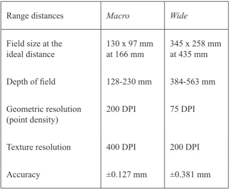
Texture resolution 400 DPI 200 DPI
Accuracy ±0.127 mm ±0.381 mm
Survey
Figure 4. Acquisition and post-processing work-fl ow correlation, thus allowing a very clear range-maps overlapping operation (for a more exhaustive examination of the functioning principles refer to Guidi et al., 2007; for other laser multiple-line triangulation technique see Matija et al., 2008).
Two are the possible scanning task modes, called Macro and Wide, differentiated by length of baseline between laser and sensor, and consecutively by working distance between scanner and object,
fi eld of view and accuracy (see Table 3). The device carries out the acquisition at a rate of about 50.000 points per second and requires about 90 seconds for each scan view (Bitelli, 2009).
2.2 Work-fl ow and problematic issues
The model reproduction process we tested on the archaeological sets and then defi ned in detailed guidelines for future applications, can be summarized in the following basic pipeline (Figure 4). Contributions to discuss and outline typical work-fl ows are in Bernardini and Rushmeier, 2002; Guidi et al., 2010; Vrubel et al., 2009:
NextEngine’s laser scanner works with highly automated procedures, and the owner software that controls the operations and the rotation on predefi ned steps of the connected turntable, ScanStudio HD, which we used to cover every step from acquisition of individual captured views of the object to fusion in a single triangle mesh, needs just a few confi gurations: therefore results are homogeneous even if different operators perform the acquisition sessions. The variety and the complexity of the artifacts require, though, training, consistency to guiding lines in all planning and processing phases and experience to apply different solutions.
All post-processing steps after mesh fusion to obtain the fi nal texturized model have been basically performed with Geomagic Studio.
As well known, the acquisition stage is very short compared to the time necessitated for elaboration of raw data. Even if it can’t be quantifi ed, given so many variables as the type of specifi c features of the object, the number of views, the expertise of the operator and the hardware potential he’s working with, the two main phases are generally in a ratio of 1 to 10 / 15.
In relation to the above-mentioned suggested protocol, the present contribution gives account of the most recurrent problematic and time-costly issues and how we faced them, throughout the pipeline stages of data capture and post-processing.
2.2.1 Survey planning and set-up: On this fi rst phase, aimed to determinate the minimum number of scans needed to capture the whole object and to set up the scene for the acquisition operations, are essentially based all further steps and the quality of attainable results.
The fi nal scope is to prevent from having blind spots in the raw data and to accomplish the most correct measurements and the most persuasive photographic information, with relation to the ideal distance required by the instrument and to the morphological complexity of specifi c types of objects, as when they feature
handles, necks or spouts or multiple footings which can hide each other, or when decorative motifs are closely incised or stamped, or when thin rims and sharp discontinuities characterize the surface profi le.
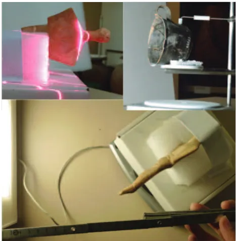
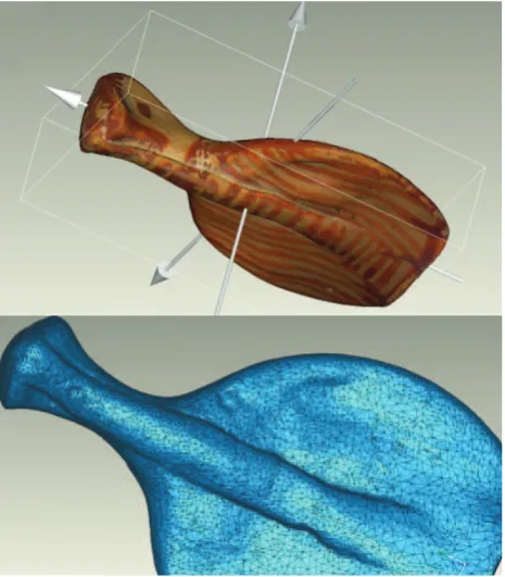
Decisions on differentiated scanning plans must be made according strictly to objects classifi cation (dimensions, shape, fi nishing, etc.) and to the reasons why each artifact has been chosen for the project. The range distance will infl uence the quality of the captured geometric and/or photographic data. To give some examples, the major concern for an object whose function is still under discussion (as the one we scanned exemplifi cative of the so called “frying pans” which were probably used as frames for mirrors) will be to have at disposal a true 3D representation of the morphology; the same applies to vessels which maintain traces of the manufacturing process (e.g. the honeycomb structured bottom of a basin which probably has been drying on a mat or rack after modeling) or of their usage, provenance and destination (e.g. the pot-mark incised before fi ring on the bottom of a fl ask used to carry oils and ointments, as possible sign to track the type of content or its quantity). In parallel, for other artifacts could be of great interest the polychromy, the surface fi nishing treatment, the decorative patterns, for expressively esthetic and stylistic concerns. Another important matter of consideration that arises is that heritage objects like these cannot be pre-treated to avoid refl ections in the textural data due to shiny surface fi nishing, or noise in the geometric data due to certain colors (black). The same high respect for the materiality of the artifacts, which are fragile and often reassembled, must orient their handling and positioning on the turntable connected to the scanner to assure safe conditions during the whole acquisition process. A series of appropriate and adapted supports to keep the object in the desired angle every time there’s a change of position will be part of the operator’s equipment on-site (Figure 5).
Lastly, it must be warningly stated that it’s not always the most appropriate choice to generate a digital model which has no resulting holes in the captured surface if, for this purpose, the overlapping portion between scans exceeded the suggested percentage (about 20%) and the angle of incidence was too much deviated from orthogonality. A not so careful planning of the
Figure 5. Above, photographic documentation of artifacts positioning; below, checking range distances
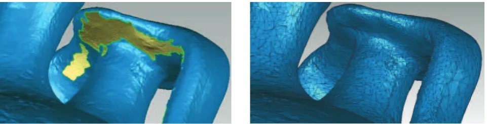
Figure 7. Portions which cannot be viewed simultaneously by emitter and receiver sensors
Figure 8. Single textured scan (right); the matching picture taken by the scanner’s camera (left) acquisition procedure can entail a dilatation of costs, in terms of
resources and time frame, not so much during the scanning stage as later on, post-processing: trimming noisy raw data becomes a slower and more tedious operation if there’s a very large amount of redundant data to be fi ltered, in order to keep the most valuable with respect to measuring preciseness and photographic quality.
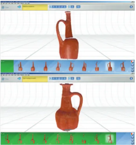
2.2.2 Data acquisition: One at a time the selected museums artifacts have been temporarily removed from their glass display cases or the museum storerooms to be placed on the turning base and scanned. For each position we performed sequences of scans (families), either completing a 360° rotation on the vertical axis to acquire the body of the object, or confi ning a section in triplets usually for summit and bottom (Figure 6); sometimes also single scans are needed for integrations.
To cover the whole object average 20 scans have been captured in approx two hours: half of this time extent is needed to study and prepare the placing of the artifact in the right perspective and to check every time the scanner’s fi eld of view in relation to the rotation of the platform.
The initial plan is generally modulated during the acquisition phase thanks to the possibility to review results immediately. On-site aligning of single scans in one family helps to orient the following sessions and, in case, to modify settings. Pictures taken of the scanning sets and neat recording of the selected settings will usefully complement the raw data archive, serving during Figure 6. Below, a sequence of three scans aligned as visualized
in ScanStudio; above, the different families not yet registered in the same reference system
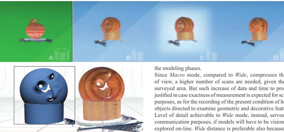
the modeling phases.
Since Macro mode, compared to Wide, compresses the fi eld of view, a higher number of scans are needed, given the same surveyed area. But such increase of data and time to process is justifi ed in case exactness of measurement is expected for scientifi c purposes, as for the recording of the present condition of heritage objects directed to examine geometric and decorative features. Level of detail achievable in Wide mode, instead, serves better communication purposes, if models will have to be visioned and explored on-line. Wide distance is preferable also because better results are obtained, compared to Macro, in undercut’s views, hollowed regions which can be diffi cult to rebuild: in Macro, size and depth of fi eld are almost half than Wide (see Table 3), often causing lack of coincidental visibility for both sensors (emitter and receiver) on the same area of the object (Figure 7).
Noteworthy is that photographs taken by NextEngine’s in-built camera show which portions of the object’s surface weren’t acquired: the parts colored darker are the ones which couldn’t be simultaneously captured by the triangulation-based scanner’s double sensors (Figure 8).
2.2.3 Alignement and mesh fusion: All range maps must go through a fi rst screening to remove portions of the protection materials and of the support on which the object was leaning or standing, and occurrent outliers (Guidi et al., 2010). Therefore, single scans fi rst and then scan families, referring to different space coordinates systems intrinsic to the instrument, are registered in one global system through rigid roto-translations. Aligning operations are semi-automatic and are performed selecting and matching at least 3 correspondence points on two separate maps in the overlapping area; in a second moment alignment is refi ned with ICP procedure.
For objects with an even appearance and not characterized by any relevant marks on the surface, a checkered pattern we laid on the support helped to single out the corresponding features during the alignment phase.
After eliminating redundant and useless data (Figure 9), the different scan families tied together are fused in a single triangle mesh.
Figure 9. Model of stirrup jar after all families have been aligned and overlapping meshes largely reduced
Figure 11. Model of a stirrup jar, before and after holes fi lling
Figure 10. Mimetic reintegration (geometry and texture) of the hole in the fi gurine’s head
the screening of the raw data through a reasoned trimming action in order to reduce overlapping of single range maps and to choose the best geometric information and RGB color texture available among the data produced automatically by the instrument. This is surely one of the longest and crucial operations of the entire processing procedure and requires persisting testing and comparing vision.
2.2.4 Editing of polygonal mesh and of texture: This phase includes the following operations when needed:
- correction of topological errors in the polygonal surface, pri-marily consisting in cleaning up and repairing irregular triangles as the ones with fl ipped normals or with redundant or intersecting faces, and removing dents and sharp edges;
- fi lling of holes in the mesh, matching its curvature, and recon-struction of internal parts of narrow openings and spouts as may be found in generated models of stirrup jars, jugs and fl asks; - texture generation for the parts that have been fi lled in and imi-tative “in-painting” through a pixel-per-pixel color replacement; - editing of the photographic texture to remove refl ections and to mitigate any discernible tone variation that derives from single scans then fused in one polygonal mesh;
- noise reduction and surface smoothing if needed.
Volumetric and chromatic reintegration compensating for una-voidable missing parts, yet limited, has not been performed in the highly detailed copy that will be used for scientifi c purposes. Before being archived, though, the number of triangles of the ori-ginal mesh may have been partially reduced (Mesh simplifi cation). A complete mimetic reconstruction has been carried out, instead, for the model which will be viewed in the virtual exhibit appli-cations, in order to give unity and formal adherence to the real object (outside and visible parts of the inside). The challenge is regulating the available hole-fi lling algorithms and confi gurations and adjusting the new integrated mesh to achieve good results (Figures 10, 11, 12).
Synchronous acquisition of photographic textural data speeds up and makes easier surveying operations. The automatic storage of a color attribute in each vertex of the polygonal mesh carries
the advantage that no further texture mapping techniques are required. Per contra the main downside is unimpressive quality of the pictures. In our case, though, this has been considered suffi ciently good for the targeted applications, and turns out to be suitable and convincing if only the best portions are combined and if certain fl aws are edited during the post-processing phase. In fact, the use of a built-in illumination device ensures the same lighting conditions anytime during the acquisitions, but produces more or less pronounced refl ections on the returned surfaces of shiny objects (Figure 13).
Tests were performed in our lab to verify what would happen with a more diffused illumination condition, placing additional lights in the set and/or isolating the object in a light box with no shadows, but results were disappointing; in fact, under certain conditions, it even occurred a signifi cant loss of geometric data. Such effect may be explained by the fact that the algorithm which analyzes the pattern projection to extract the 3D information turns out to be very dependent on the in-built light color temperature (which evidently must have been calibrated in relation with the properties of the signal projected on the object).
These disadvantages could be overcome laying on the geometry acquired by the scanner high resolution photographic texture obtained under better lighting conditions with a separate camera and more qualitative lens, using calibration techniques (Vrubel et al., 2009). Such procedure, though, would imply a considerable increment of time and of the operator’s action, nullifying all be-nefi ts previously mentioned.
to about 100.000, depending on the morphological complexity of the artifact, may be partially reduced if the triangle count is very high; the versions designed for didactic and informative interaction in virtual displays will be decimated from 30 to 70% for off-line applications, maintaining 80.000/50.000 polygons, and up to 95% for Web applications, resulting 10.000/5.000 polygons in the end. If examined at the real scale and without texture, these low-poly models show in all their abruptness the loss of geometric quality and detail; but overlaid texture is able to disguise what seemed inacceptable, allowing for swift loading and handling (Figure 14).
2.2.6 Export in storage formats: When the models are ready, Geomagic WRP fi les are converted into OBJ and 3DS formats, which defi ne and fi le geometry and also texture information and are supported by most applications, but likewise could be saved in many other output data confi gurations.
The verifi cation of Web interaction functionalities and any con-sequent models’ adjustment are the next goals scheduled for the oncoming future.
All fundamental steps of the processing work-fl ow are recorded and sorted in the project’s data archive and backed on hard drive for permanent storage.
Figure 14. Model of a fi gurine of a rider on a horse before (102.000 triangles: above) and after decimation (~5.000 triangles: center and below, texturized)
3. CONCLUSIONS
The present contribute has shown how a low-cost range-based system is qualifi ed to capture a wide set of archaeological pottery and sculpted fi gurines denoted by different and specifi c features (shape, size, color, surface fi nishing, etc.) and which are the critical phases of the defi ned work-fl ow, in relation to 3D modeling
fi nalities. In particular, research has been case-based on the digital reproduction of such objects to implement a scholars’ archive for further scientifi c activity with high resolution, faithful and measurable models (Figure 15), and to provide content for virtual exhibitions on the Web with lower resolution and geometrically simplifi ed ones, not excluding the possibility of using a medium level for real time visualization on stand-alone interfaces situated in the actual physical museum spaces (Figures 16, 17).
Figure 12. Beginning the volumetric reconstruction of the hidden part of a handle, bridging the gap
according to local curvature
Figure 16. Polygon model of a female fi gurine with folded arms
Figure 15. Bidimensional representation extracted from the polygon model of an incised ceramic bowl, to show
contextually inside (section) and outside, as a conventional survey drawing of the artifact
4. REFERENCES
Arnold, D., Geser, G., 2008. EPOCH Research Agenda for the Applications of ICT to Cultural Heritage. EPOCH Publication. Download available on http://epoch-net.org/index.php
Bernardini, F., Rushmeier, H. E., 2002. The 3D Model Acquisition Pipeline. Computer Graphics Forum, vol. 21(2), pp. 149 – 172.
Bitelli, G., Simone, A., Girardi, F., Lantieri, C., 2009. Caratterizzazione di superfi cie e tessitura del manto stradale mediante tecniche a scansione laser. In: Bollettino della Società Italiana di Fotogrammetria e Topografi a, Arti Grafi che Pisano, Cagliari, n. 3, pp. 55 – 68.
Bruno, F., Bruno, S., De Sensi, G., Luchi, M. L., Mancuso, S., Muzzupappa, M., 2010. From 3D reconstruction to virtual reality: A complete methodology for digital archaeological exhibition.
Journal of Cultural Heritage 11, 1, pp. 42 – 49.
Gallo, G., Milanese, F., Sangregorio, E., Stanco, F., Tanasi, D., Truppia, L., 2009. ‘Coming back home’. Il modello virtuale della statua romana di Asclepio del Museo di Siracusa (Italia). In: I Congreso Internacional de Arqueología e Informática Gráfi ca, Patrimonio e Innovación, Arqueológica 2.0. Sevilla, España, pp. 417 – 421.
Guidi, G., Remondino, F., Morlando, G., Del Mastio, A., Uccheddu, F., Pelagotti, A., 2007. Performances evaluation of a low cost active sensor for cultural heritage documentation. In: Proceedings of the VIII Conference on Optical 3D Measurement Techniques, Zurich, Switzerland, Vol. 2, pp. 59 – 69.
Guidi G., Russo M., Beraldin J.A., 2010. Acquisizione 3D e modellazione poligonale, McGraw-Hill.
Jasink A. M., Bombardieri L., 2009. Le collezioni egee del Museo Archeologico Nazionale di Firenze. F.U.P. Firenze University Press, Florence, Italy.
Matija, J., Matjaž, F., Janez, M., 2008. Laser Multiple Line Triangulation System for Real-time 3-D Monitoring of Chest Wall During Breathing. In: Journal of Mechanical Engineering, Strojniški vestnik, 54, 7-8, pp. 503 – 506.
Menci, L., Nex, F., Rinaudo, F., 2007. ZScan Menci Software: un nuovo strumento per le elaborazioni fotogrammetriche multimmagine. In: Proceedings of the XI Conferenza Nazionale ASITA, Turin, Italy, Vol. 1, pp. 1 – 2.
Peripimeno, M., Salvadori, F., 2007. Lo sviluppo di nuovi percorsi di documentazione archeologica. In: Introduzione all’uso della ceramica in archeologia, Centro Editoriale Toscano sas, Firenze, pp. 101 – 114.
Scopigno, R., 2005. Gestione effi ciente dei dati prodotti dai sistemi di scansione tridimensionale. In: Laser Scanner e GPS: Paesaggi Archeologici e Tecnologie Digitali. Edizioni All’Insegna del Giglio, Firenze, pp. 41 – 68.
Sylaiou, S., Liarokapis, F. , Kotsakis, K., Patias, P., 2009. Virtual museums, a survey and some issues for consideration. Journal of Cultural Heritage 10, 4 (Oct.-Dec. 2009), pp. 520 – 528.
e modellazione 3D per un allestimento interattivo e accessibile da Web. Archeomatica, Tecnologie per i Beni Culturali, anno 1, n. 3, pp. 30 – 33.
Tucci G., Bonora V., Costantino F., Ostuni D., 2004. Metodi di rilievo tridimensionale a confronto: affi dabilità metrica e capacità descrittiva. In: Proceedings of “e-Arcom 2004 - Tecnologie per Comunicare l’Architettura” Workshop. Ancona, Italy, pp. 553 – 558.
Tucci, G., Bonora, V., 2007. Application of high resolution scanning systems for virtual moulds and replicas of sculptural works. In: Proceedings of the XXI International CIPA Symposium “AntiCIPAting the future of the cultural past”, Athens, Greece, Vol. 1, pp. 721 – 726.
Vagnetti, L., Bettelli, M., Di Paolo, S., 2007. La collezione ci-priota del Museo Archeologico di Firenze nel quadro della storia e dell’archeologia di Cipro. In: Guidotti, M. C., Lo Schiavo, F., Pierobon Benoit, R. (Eds.). Egeo, Cipro, Siria e Mesopotamia. Dal collezionismo allo scavo archeologico. In onore di Paolo Emilio Pecorella. Sillabe, Livorno, Italy, pp. 132 – 173.
Vrubel, A., Bellon, O. R. P., Silva, L., 2009. A 3D Reconstruction Pipeline for Digital Preservation of Natural and Cultural Assets. In: Proceedings of 2009 IEEE Conference on Computer Vision and Pattern Recognition, Miami, USA, pp. 2687 – 2694.
5. ACKNOWLEDGEMENTS