DEVELOPMENT OF A HYBRID UAV SENSOR PLATFORM SUITABLE FOR
FARM-SCALE APPLICATIONS IN PRECISION AGRICULTURE
Pircher M.a, Geipel J.a, Kusnierek K.a, Korsaeth A.a
aNorwegian Institute of Bioeconomy Research, Pb 115, 1431 Ås, Norway [email protected]
KEY WORDS: UAV, Fixed-wing, Multi-rotor, Hybrid, VTOL, Autonomous, Precision agriculture
ABSTRACT:
Today’s modern precision agriculture applications have a huge demand for data with high spatial and temporal resolution. This leads to the need of unmanned aerial vehicles (UAV) as sensor platforms providing both, easy use and a high area coverage. This study shows the successful development of a prototype hybrid UAV for practical applications in precision agriculture. The UAV consists of an off-the-shelf fixed-wing fuselage, which has been enhanced with multi-rotor functionality. It was programmed to perform pre-defined waypoint missions completely autonomously, including vertical take-off, horizontal flight, and vertical landing. The UAV was tested for its return-to-home (RTH) accuracy, power consumption and general flight performance at different wind speeds. The RTH accuracy was 43.7 cm in average, with a root-mean-square error of 39.9 cm. The power consumption raised with an increase in wind speed. An extrapolation of the analysed power consumption to conditions without wind resulted in an estimated 40 km travel range, when we assumed a 25 % safety margin of remaining battery capacity. This translates to a maximal area coverage of 300 ha for a scenario with 18 m/s airspeed, 50 minutes flight time, 120 m AGL altitude, and a desired 70 % of image side-lap and 85 % forward-lap. The ground sample distance with an in-built RGB camera was 3.5 cm, which we consider sufficient for farm-scale mapping missions for most precision agriculture applications.
1. INTRODUCTION
The purpose of this paper is to show the development of an unmanned aerial vehicle (UAV) sensor platform, which is suitable for farm-scale applications in precision agriculture; being both user-friendly and efficient. UAVs have been used for different purposes in precision agriculture, such as optical remote sensing of biomass and fertilization demand in wheat (Geipel et al., 2016), multispectral imaging for weed detection (Torres-Sànchez et al., 2015), and thermal imaging for stress detection in spring wheat (Kusnierek and Korsaeth, 2014).
At time being, the rising UAV industry has many different UAV platforms to offer of which fixed-wing and multi-rotor UAVs are the dominant types. However, platforms, which are suitable for farm-scale applications, being both efficient in terms of area coverage and user-friendly are scarce. Most of the UAVs on the market lack either a high degree of automatization or sufficient flight time and airspeed.
Fixed-wing UAVs have the advantage of long flight times and high airspeeds, which, in combination, lead to a high area coverage and efficient remote sensing missions. Moreover, they are suitable to carry heavy payloads. The major drawbacks are the need for open space and landing strips as well as intensive manual interactions during start and landing procedures, which must be adapted to the mission environments. This often prohibits the possibility of autonomous landing manoeuvres. The landings are commonly rough and require special considerations for the protection of sensitive sensor payloads. From a practical perspective, creative landing methods like a parachute (Wyllie, 2001) or conventional belly landing are, thus, unsuitable.
Multi-rotor UAVs are known for shorter flight times and lower airspeeds than the fixed wing ones, leading to a decreased area
coverage. Carrying heavy payloads leads to a significant reduction in flight time and, thus, is generally avoided in farm-scale applications. The easy handling, even in obstructed environments, and the highly automatized vertical take-off and landing (VTOL) capabilities are the major advantages compared to fixed-wing systems.
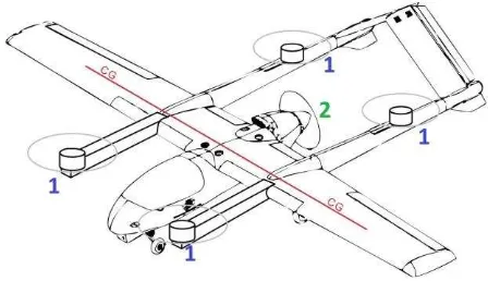
To eliminate the drawbacks of the two platform types, the most obvious solution is to develop a platform that combines their advantages; a hybrid fixed-wing UAV equipped with a multi-rotor setup, enabling VTOL capabilities (Figure 1).
Figure 1. Sketch of a hybrid fixed-wing UAV with four vertical lift motors (1) and one pusher motor (2) for forward flight. The
centre of gravity is illustrated in red (CG) (adapted from RMRC, 2014)
With such a hybrid UAV, it is possible to have the long range and high payload capabilities of a fixed-wing and the automatized and landing strip independent VTOL capabilities of a multi-rotor UAV. A further advantage of a hybrid UAV is the possibility of selecting a propeller and power train for the pusher motor, customized for an efficient forward cruise flight. As take-off from a runway is not required, the pusher motor does not need to be optimized for the high level of thrust necessary for a conventional take-off.
At time being, there are several commercial hybrid UAVs on the market like the FireFLY 6 (BirdsEyeView Aerobotics, 2017) and the Quantum Tron (Quantum-Systems, 2017). To our knowledge, they all lack an offer for an integrated hyperspectral sensor payload, which is desired in most agricultural applications. Therefore, we decided to build a hybrid UAV customized for our mission requirements. Due to the complexity of this task, we built a prototype first to gather experience and to evaluate its flight performance (an up scaled and improved hybrid UAV is in the pipeline). Here, our focus was to learn about the avionics, the flight controller, and the multi-rotor setup. In conjunction, we also gained experience in utilizing the ArduPlane firmware that we target to use for a future fully functional hybrid UAV, which is capable of carrying hyperspectral imaging systems that are crucial for advanced remote sensing applications in precision agriculture. The hyperspectral sensor payload was not part of this study and will be addressed later. The prototype UAV was only equipped with simple RGB cameras to test the capability of collecting data.
2. MATERIALS AND METHODS
2.1 System Setup
The prototype hybrid UAV system consists of the hardware, the software, and the payload segment. In addition to that, a ground station segment was used to control and monitor the flight mission.
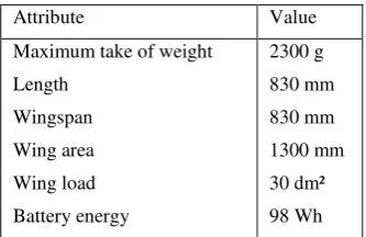
2.1.1 Hardware Segment: The hardware segment comprises the fuselage, the power trains (fixed-wing and rotary-wing), and all electronic components that are needed to control the UAV. An overview of the technical data are shown in Table 1.
Attribute Value
Maximum take of weight 2300 g
Length 830 mm
Wingspan 830 mm
Wing area 1300 mm
Wing load 30 dm²
Battery energy 98 Wh
Table 1. Overview of the major technical specifications of the hybrid UAV prototype
A V-tail model airplane (X-UAV Mini Talon) was used as fuselage (Fig. 2). It consists of high-density Expanded Polyolefin (EPO) foam. EPO is a lightweight, durable, and crash resistant material, which guarantees high payload capacities. Two strong carbon fibre rods were mounted as spars into the wings for torsion-resistance and flex. Four servo actuators (Turnigy TGY-113MG) with a torque of 2.2 kg were used to operate the control surfaces. For propulsion, a 1250 KV brushless motor (Tiger
Motor AT2216) with an 8 x 6 inch propeller (APC) was used in combination with a 40 A rated electronic speed controller (ESC; BlueSeries). All propellers were carefully balanced using a propeller balancer (Du-Bro 499 Tru-Spin). The ESC also has a solid inbuilt 5.5 V 5 A switching battery eliminator circuit, that powers the accessories and avionics of the UAV. The battery is a high capacity four-cell lithium polymer (LiPo) battery (MultiStar) with a nominal voltage of 14.8 V and a capacity of 6600 mAh. With only 537 g of weight, it has a good energy density and a high constant discharge rating of 66 A.
Figure 2. Hybrid UAV with enhanced rotary-wing capabilities, hovering 50 m AGL over the test location at Apelsvoll research
station (image taken from a multi-rotor UAV) The self-developed power train for the rotary-wing enhancement consists of four highly efficient brushless motors (MT3506, Tiger Motor) with 650 KV and a maximal continuous power output of 260 W and 70 g weight each. Stiff 12 x 4 inch moulded carbon fibre propellers (Tiger Motor) were selected for this setup. Four ESCs (Favourite FVT LittleBee Spring) with a maximum rating of 30 A current were used to drive the motors. These ESCs have a high efficiency guaranteeing low heat build-up, an exceptional fast switching speed that is essential for stable flight in rotary-mode, and low energy consumption while hovering. The motors were mounted on the ends of two square carbon fibre tube spars (15 x 15 mm) which were firmly attached to the wings of the UAV (see Fig. 2). These spars are stiff and ensure together with the wing spars low flex during the transition phase when the torsion forces are maximal. Additionally, four high power 1 W light-emitting diodes were attached for better visibility.
A DroPix autopilot system (Drotek), which is a derivate of the proven and well-known PX4 autopilot from ETH Zurich, was implemented. The DroPix features a 32-bit ARM Cortex® M4 Processor, a barometer (MEAS MS5611), a three axis 16-bit gyroscope (L3GD20), a combined three axis 14-bit accelerometer and magnetometer (LSM303D), and a redundant combined three axis accelerometer and gyroscope (Invensense MPU 6000). It has several safety features like three independent power supplies, an integrated backup system for in-flight recovery, and an external safety button for arming the motors. Its on-board micro SD card was used for high rate logging of sensor data, position, and flight information. The autopilot was mounted vibration-cushioned with four rubber dampers. In addition, a 72-channel global navigation satellite (GNSS) receiver (Ublox NEO-M8N) was used in combination with a supplementary magnetometer (HMC5983). The magnetometer was mounted at some distance apart from high power wiring, motors, and other sources of magnetic disturbance, to ensure improved heading estimates. Moreover, a pitot tube for measuring the actual airspeed was installed together with a digital differential airspeed The International Archives of the Photogrammetry, Remote Sensing and Spatial Information Sciences, Volume XLII-2/W6, 2017
sensor (4525DO Measurement Specialties) with a resolution of 0.84 Pa.
In order to measure the power consumption, actual current and voltage was detected with a shunt current sensor and the DroPix’s analogue voltage reading pins. The current sensor was calibrated with an accurate multimeter (Mastech MAS830L) to improve its sensing accuracy. A voltage divider was installed in between the battery and the DroPix to reduce the voltage to an acceptable level (< 3.3 V) for the analogue voltage reading pins.
2.1.2 Software Segment: On the software side, the open source Arduplane 3.6.0 firmware was used for the DroPix flight controller. To be able to use this firmware for rotary-wing mode, it was essential to set the “Q_ENABLE” parameter to one. This unlocked a set of required parameters for rotary-wing operation. The most important parameters that were set were “Q_THR_MIN_PWM” and “Q_THR_MAX_PWM” to configure the throttle range of the vertical lift motors. Additionally, it was required to set the proportional–integral– derivative (PID) controller for flying to rotary-wing mode with the parameters “Q_A_RAT_RLL_P” and “Q_A_RAT_PIT_P”. To prevent throttle surge during transition, the optimal throttle output, needed to hover in rotary-wing flight mode, was calculated and used to set “Q_THR_MID”. As ground control software for setup, mission planning, and parameterization, Mission Planner 1.3.44 (Oborne, 2017) was used.
2.1.3 Ground Station Segment: In order to guarantee a continuous live data stream and a secure control of the UAV, two digital and one analogue radio links were installed. For control, a FrSky Taranis X9D PLUS radio was used. It features 16 individual control channels and is fully programmable with the OpenTX software. Its frequency hopping ACCST technology takes advantage of the entire 2.4 GHz band to provide a reliable low latency control link. As receiver, a FrSky X8R 8/16 channel ACCST telemetry receiver with an operating range of more than 1.5 km was used.
For live data display at the ground station laptop (DELL Latitude E7470) and for modifying UAV and mission parameters on-the-fly, a two-way full-duplex 433 MHz serial UART telemetry link was set up. With a -117 dBm receive sensitivity and good custom antennas, these telemetry radios provide a sufficiently long range at a legal and licence-free 10 mW power output.
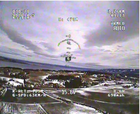
For live flight video display, a PAL video signal was used. It was received on the ground by a 10" monitor (Foxtech Explorer) with an inbuilt diversity video receiver. A screenshot is shown in Figure 3.
2.1.4 Payload Segment: As payload, a modified RGB camera with only 17g weight was selected. It consists of an Ambarella A7LS processor and a 16 megapixel BSI-CMOS image sensor (SONY Exmor R). A custom lens with an F-stop of 2.8 and a focal length of 4.35 mm was mounted to the sensor. The sensor was installed on the bottom of the fuselage, decoupled for low vibration and in nadir view position. The camera was triggered by a pulse width modulation (PWM) signal from the DroPix. The raw image data was stored on a micro SD card. A second RGB camera (Foxeer HS1190) with a CCD image sensor (Sony SUPER HAD II) was mounted in front view at the nose of the UAV and used for live video transmission only. Both cameras were connected to a video transmitter (TBS UNIFY PRO) to transmit their analogue video signal to a ground station via a reliable 5.8 GHz analogue video downlink. All vital flight data (e.g. the artificial horizon, voltage, airspeed, amperage, altitude,
GNSS quality, and others) were overlaid on the video signal by an on-screen-display (OSD, PlayUAV). The OSD was configured to let the UAV operator switch between the two camera views via remote control.
Figure 3. Screenshot of the live video feed of the front camera with overlaid flight data during an autonomous flight over the
test area
2.2 Experimental Setup
For UAV parametrization, the mandatory accelerometer calibration was performed for the temperature range that the UAV was exposed for in the experimental setup. The endpoints of the radio control channels were calibrated to ensure full travel range. The two on-board compasses were calibrated in a three dimensional motion to provide valid offsets for the magnetic on-board interference. All calibrations were stored on the DroPix. To determine the optimal flight parameters for the UAV, several manually controlled test flights were performed. During these flights, the AUTOTUNE procedure of the ArduPlane firmware was conducted to calculate a good set of roll/pitch PID parameters on-the-fly. In addition, the minimum, maximum, and stall airspeed was determined manually. These values were then saved and used for autonomous flights to prevent unpredictable attitude and dangerous stalls.
After parametrization and calibration, several fully autonomous flight missions were executed during two weeks in March 2017 at different weather conditions and different daytimes at the Apelsvoll research station in southeast Norway (60°41'57" N, 10°52'05" E). The flight missions were set up to determine the return-to-home (RTH) landing precision and the power consumption of the UAV at different wind speeds.
The landing precision was tested by launching the UAV from a marked position (Fig. 4) and measuring the distance between the starting and the landing location. The mission was performed ten times at different times of the day to cover different GNSS satellite constellations. To ensure sufficient GNSS signal quality, acquisition of a minimum of 15 satellites and a positional dilution of precision (PDOP) value below one was selected as thresholds for off. Together with the command for motor start and take-off, the UAV saved its actual GNSS position as the RTH point. The UAV was programmed to take off vertically to a height of 50 m above ground level (AGL) and a subsequent transition to horizontal flight in fixed-wing configuration. In this The International Archives of the Photogrammetry, Remote Sensing and Spatial Information Sciences, Volume XLII-2/W6, 2017
configuration, the UAV flew five circles with 300 m diameter each, following a transition to vertical flight in rotary-wing configuration. Then it performed an autonomous landing at the RTH point. The actual residual distance in between the landing point and the ground mark was measured with a measuring tape.
The power consumption was tested by setting up a waypoint mission to cover a test field for a photogrammetric survey with constant image overlap and flying altitude. Three flight missions were performed, at wind speeds of 0, 5 and 7 m/s, respectively. The flight direction pattern was laid out orthogonally to the wind direction to ensure a constant airspeed for sufficient image overlap. The disadvantage of flying orthogonally to the wind is an increase in the drift angle (also called “crab angle” because of the lateral movement of the aircraft). An increase in the drift angle leads to the need of a higher image overlap. Therefore, the flight pattern was adjusted to the actual wind direction at each mission. The DroPix was set up to trigger the camera at every 45 m of distance travelled. As in the previous mission setup, the UAV was programmed to take off vertically to a height of 50 m AGL and a subsequent transition to horizontal flight in fixed-wing configuration. In this configuration, the UAV climbed to 120 m AGL and started to execute the waypoint pattern over the test field. After reaching the last waypoint of the pattern, the UAV performed a transition to rotary-wing configuration and landed autonomously at the RTH point. Subsequently, the in-flight voltage and amperage values were downloaded from the flight log; the wattage need was calculated for every flight mission individually and compared to each other. The acquired images of the modified RGB camera were downloaded and geotagged with the location information from the log files of the DroPix. The geotagged images were processed with Agisoft Photoscan 1.3.0 to a point cloud, an orthomosaic and a digital surface model (DSM).
All flight logs were evaluated for the UAV’s flight behaviour and possible error outputs of the DroPix. The intensities of the logged vibrations were analysed using Mission Planner to graph the VIBE message’s “VibeX”, “VibeY” and “VibeZ” values, which are the standard deviation of the primary accelerometer’s output in m/s².
To evaluate the number of occurrences where the accelerometer’s digital measurement range was exceeded, the “Clip0” counter was checked. This counter increases by one at every time the accelerometer reaches its maximum digital value.
The plausibility of the PID controller settings were also rated; this was accomplished by comparing the logged values of “ATT.DesRoll” with “ATT.Roll”. The first parameter is the desired roll angle, set by the DroPix flight controller. The second parameter is the actual roll value that the UAV achieved. Accordingly, the same procedure was done for “ATT.DesPitch” and “ATT.Pitch”, indicating the pitch angle.
All experimental flights were performed in accordance with the rules laid out by the Norwegian civil aviation authority. All autonomous missions were monitored in line of sight by a pilot who could take over control at any time in case of an error or another aircraft approaching at low altitude.
Figure 4. Overview of the equipment with ground station laptop, UAV, ground mark, remote control, and live video
screen
3. RESULTS
All flight missions were accomplished as planned. The UAV behaved like expected and no errors were logged by the DroPix. Exceeding a wind speed of 11 m/s, the UAV was not able to maintain its position in rotary-wing auto mode and drifted in wind direction.
The average measured RTH accuracy was 43.7 cm with a root-mean-square error (RMSE) of 39.9 cm. The maximal measured distance to the ground mark was 140 cm whereas the minimal distance was 4 cm.
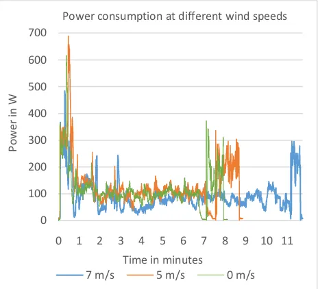
The three waypoint missions to test the power consumption were accomplished successfully. The UAV took off, climbed to the programmed altitude, and reached all waypoints successfully before landing at the RTH point. No manual inputs were required. The results of the actual power consumption are shown in Figure 5.
Figure 5. Power consumption over time for three waypoint missions at different wind speeds
0 100 200 300 400 500 600 700
0 1 2 3 4 5 6 7 8 9 10 11
Po
w
e
r
in
W
Time in minutes
Power consumption at different wind speeds
7 m/s 5 m/s 0 m/s
The power consumption of the missions performed at three different wind speeds followed a similar pattern (Fig. 5). Each mission showed steep increase at take-off to a plateau of around 250 W followed by a peak at minute one of up to 700 W. Then the consumptions decreased to a stable value of around 100 W, followed by an increase to a second plateau around 250 W towards the end of the mission. The duration of a mission was in the range of 8-12 minutes.
The modified camera acquired 154 sharp images (Fig. 6) at each mission. The images were successfully geotagged with the positions, provided by the log files of the DroPix.
Figure 6. Crop of an image taken at 120 m AGL with the modified RGB camera
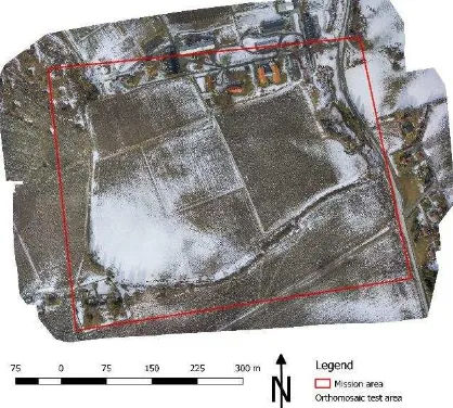
Agisoft Photoscan processed all images to the desired point cloud, orthomosaic (Fig. 7), and DSM without any error messages.
Figure 7. Orthomosaic of the test area with the outlines of the mission area in red
The vibration values of “VibeX”, “VibeY” and “VibeZ” were below 10 m/s², with occasionally peaks of up to 20 m/s². The “Clip0” value was 0 in-flight but it increased to 1 at two landings.
The values of the variables “ATT.DesRoll” and“ATT.Roll” were almost identical, and “ATT.DesPitch” and “ATT.Pitch” behaved
similarly. The average deviation in angle for all flights in fixed-wing mode was 2.1° for roll and 2.6° for pitch.
4. DISCUSSION
The evaluation of the ten RTH and the three waypoint missions shows that the prototype hybrid UAV works under realistic conditions and handle a wide range of wind speeds.
One limiting factor for the hybrid UAV flying in rotary-wing mode is its big surface (i.e. the fixed wings not in use), which makes it sensitive for wind. This could be observed as drift of the UAV by wind speed exceeding 11 m/s. For safety reasons, we will therefore use the UAV at a maximum wind speed of 9 m/s in future missions. A possible solution to be able to fly above this level may be to turn the UAV in the wind direction to reduce its attack surface and to use the pusher motor for holding its position. This feature will be implemented in the future firmware version (3.7.0) of ArduPlane.
The RTH error was unexpectedly low, especially with regard to the mounted single-frequency GNSS receiver. A reason for this may be the good conditions in the experimental setup. In many scenarios, the conditions could be worse (i.e. trees or buildings blocking or reflecting GNSS signal in the landing area). Therefore, a dual-frequency GNSS receiver with real-time kinematic functionality and an image-based navigation system may further improve the performance.
The power consumption analysis showed the differences in power needed for fixed-wing and rotary-wing configuration. The differences in flight time shows that the UAV needs longer time to complete the mission at higher wind speeds, which results in a higher overall power consumption. The two plateaus of around 250 W show the power that is required in rotary-wing configuration at take-off and landing. The fixed-wing flight showed a constant need of only 100 W which is considered as very efficient. The Peaks at around minute one up to 700 W were due to the transition phase, when the vertical lift motors were still running to provide lift, and the pusher motor engaged with full power to accelerate the UAV. The high power consumption in rotary-wing configuration justify an improvement in mission planning (i.e. lower the transition altitude) to further shorten the rotary-wing flight time to save energy for an increase in flight time. The low variation in power consumption in fixed-wing mode showed that the mission planning orthogonally to the actual wind speed was reasonable. An extrapolation of the measured power consumption, considering a 25 % safety margin of remaining battery capacity, results in an estimated 40 km travel range. This translates to a maximal area coverage of 300 ha at 0 m/s wind speed, 18 m/s airspeed, 50 minutes flight time, 120 m AGL altitude, and a desired 70 % of image side-lap and 85 % forward-lap. The ground sample distance is 3.5 cm with this configuration. These values are very promising concerning our requirements for a UAV sensor platform suitable for farm-scale applications.
The vibration values below 20 m/s² can be regarded as sufficiently low with regard to the recommended threshold of 60 m/s² in the ArduPlane online manual (ArduPilot, 2017). The UAV benefits of the dampening of the DroPix, the use of high quality motors, balanced propellers, and the sturdiness of the fuselage.
The increase in “Clip0” to a value of 1 at two landings is not regarded as critical. The reason is the saturation of the The International Archives of the Photogrammetry, Remote Sensing and Spatial Information Sciences, Volume XLII-2/W6, 2017
accelerometer values, influenced by a vibrational shock that is caused by the bump when the plane hits the ground at landing.
The low deviation in actual and desired pitch and roll angle indicates that the AUTOTUNE feature of the ArduPlane firmware worked reliably, and the PID values were reasonable good for the UAV. The UAV benefits from its sturdy fuselage, good vibration dampening, low clearance and flex of the linkage between the servo attenuators and the control surfaces.
5. CONCLUSIONS
This study shows the successful development of a prototype hybrid UAV suitable for farm-scale applications in precision agriculture. The UAV comprises the advantages of both a fixed-wing and a multi-rotor platform, featuring a high area coverage and a high degree of automatization in mission execution. It is able to perform pre-defined waypoint missions completely autonomously without any manual interaction. The promising results of this prototype encouraged us to continue the work on a fully functional hybrid UAV, which is capable of carrying hyperspectral imaging systems that are crucial for advanced remote sensing applications in precision agriculture. The future hybrid UAV will be an up-scaled platform with a higher payload capability for an extended hyperspectral sensor setup, at even higher flight time.
6. REFERENCES
Geipel, J., Link, J., Wirwahn, J. A., Claupein, W. 2016. A Programmable Aerial Multispectral Camera System for In-Season Crop Biomass and Nitrogen Content Estimation.
Agriculture, 6(1), 4.
López-Granados, F., Torres-Sànchez, J., De Castro, A. I., Peña-Barragán, J. M., 2016. Object-based early monitoring of a grass weed in a grass crop using high resolution UAV imagery.
Agronomy for Sustainable Development, 36(4), 67.
Kusnierek, K., Korsaeth, A., 2014. Challenges in using an analog uncooled microbolometer thermal camera to measure crop temperature. International Journal of Agricultural and Biological Engineering, 7(4), pp. 60-74.
Wyllie, T., 2001. Parachute recovery for UAV systems. Aircraft Engineering and Aerospace Technology, 73(6), pp. 542-551
RMRC, 2014. Anaconda Manual V4, Ready Made RC LLC., 2014 Revision, https://www.readymaderc.com
BirdsEyeView Aerobotics. 2017. Firefly 6. https://www.birds eyeview.aero/products/firefly6. Accessed on 01/04/2017.
Quantum Systems GMBH, 2017. Quantum Tron. https://www.quantum-systems.com/products/
quantum-tron/. Accessed on 01/04/2017.
Oborne, M., 2017. Mission Planner http://ardupilot.org/planner/ docs/mission-planner-overview.html. Accessed on 01/04/2017.
ArduPilot, 2017. Ardupilot Dev Team,
http://ardupilot.org/copter/docs/common-measuring-vibration.html. Accessed on 01/04/2017.