Open Geospatial Consortium Inc.
Date: 2009-01-15
Reference number of this document:
OGC 08-126 (used to be 99-105r2.doc)
Version:
5.0
Category: OpenGIS®
Abstract Specification Topic Volume
Editors: Cliff Kottman and Carl Reed
The OpenGIS
®
Abstract Specification
Topic 5: Features
Copyright © 2009 Open Geospatial Consortium, Inc. All Rights Reserved. To obtain additional rights of use, visit http://www.opengeospatial.org/legal/.
Document type:
OpenGIS
®Abstract Specification
Document subtype:Topic Volume
Revision History
Date Description
20 January 1998 renumber and update copyrights for 1998; add sections 2.11 and 2.12 (RFP1 status); renamed 98-105r1
28 January 1998 update with CORBA conclusions; incorporate Grant Ruwoldt’s clarifications on feature, feature type, feature collection , etc. into section 3; remove feature type and feature collection object models; renamed 98-105r1a
11 January 1999 Updates to 98-105r1a from project document 98-056, approved December 1998; remove references to “OID”; remove section 3.8 of 98-056 as suggested by author; remove future work items as suggested by author of 98-056; reconstitute from 98-105r1 lost feature collection content; use new template format; update copyrights for 1999; renamed as project document 99-105
15 February 1999
Added UML diagrams for FT_Feature as discussed in Atlanta TC, some informal text representing future work in Section 3 moved to Section 4. Renamed 99-105r1, fixed cross-references in Figure 2-14.
24 March 1999 Renamed to 99-105r2; updated for new document template following guidance of change proposal 99-010 w/ friendly amendments to remove Section 1 boilerplate from individual topic volumes, approved 9 February 1999; added Appendix C, from change proposal 98-072 (approved February 9, 1999), and reference to it in Section 2.10. August 2008 Bring into line with other OGC AS Topic Volumes and OGC Standards Baseline and
Table of Contents
1.
Introduction ... 1
1.1. The Abstract Specification ...1
1.2. Introduction to Features ...1
1.3. Information Models ...1
1.4. Terms and Definitions ...2
1.5. References for Section 1 ...2
2.
The Essential Model for Features ... 3
2.1. General Notion of Geographic Information ...3
2.2. Introduction to the Notion of a Information Community ...4
2.3. The Real World ...5
2.4. The Conceptual World ...6
2.5. The Geospatial World ...7
2.6. The Dimensional World ...9
2.7. The Project World (or The “World View”) ...10
2.7.1. Introduction to the Modeling of Geospatial Features ... 10
2.7.2. Introduction to the Project World from the “Feature With Geometry” Point of View ... 10
2.7.3. Project World Feature Instances ... 11
2.7.4. Project World Feature Types ... 12
2.7.5. Project World Geometry ... 12
2.7.6. Project World Envelope ... 12
2.7.7. Project World Geometry Schema ... 12
2.7.8. Coordinate reference System ... 12
2.7.9. Project World Attribute-Value Pairs ... 13
2.7.10. Project World Attribute Schema and Feature Schema ... 14
2.7.11. Project Schema ... 15
2.8. The OpenGIS Point World ...17
2.9. The OpenGIS Geometry World ...18
2.10. The OpenGIS Feature World ...20
2.10.1. Feature Collections ... 21
2.10.2. Interfaces on Feature Collections ... 22
2.10.3. Background Notes on Feature Collections ... 22
2.11. Summary of the Nine Layer Model ...23
2.12. An Alternative Perspective to the Nine Layer Model ...24
2.13. Persistent Feature Identifiers ...25
2.13.1. Problem Statement ... 25
2.14. Resolving Scoped Feature Identifiers...26
2.14.1. Fundamental Ideas ... 26
2.14.2. Key concept ... 26
2.14.3. Key supporting concept ... 26
2.14.4. Principles ... 27
2.14.5. Resolver Services ... 28
2.14.6. Further Example ... 29
2.14.7. Hints ... 29
2.14.9. Uniform Resource Names ... 30
2.14.10. What resolution does ... 30
2.14.11. Resolution, discovery and access ... 30
2.14.12. Handles and descriptors ... 31
2.14.13. Permanent scope objects ... 31
2.14.14. Uniqueness of identifiers ... 31
2.14.14.1. The same feature can be in several Scopes ... 31
2.14.14.2. An identifier cannot be a leaf in more than one scope ... 31
2.14.15. Uniqueness and equality ... 31
2.14.16. Internal identifiers and internal scopes ... 31
2.14.17. Scope aliases ... 32
2.14.18. Published identifiers ... 32
2.14.19. FeatureCollection ... 32
2.14.20. Methods of Feature Identity Scope ... 32
2.15. Feature Identifier Change Registries: Incremental Publishing...33
2.15.1. Conflict ... 33
2.15.2. Fundamental Ideas ... 33
2.15.3. New concept ... 34
2.15.4. Incremental Publishing ... 34
2.15.5. Incremental Publishing ... 34
2.15.6. Non-tree client network ... 35
2.15.7. Distributed Editing ... 35
2.15.8. Responsibilities and compositions... 36
2.15.9. Local cleanliness ... 36
2.15.10. Out of control copying ... 36
2.15.11. Handles for servers ... 37
2.15.12. Identifier update packet ... 37
2.15.13. Relationships ... 37
2.15.14. GIS requirements ... 37
2.15.15. Last word ... 37
2.16. Status of the Feature Specification ... Error! Bookmark not defined.
2.17. References to Section 2 ...37
3.
The Abstract Model for Feature, Feature Identifier, Identifier Scope,
Identifier Change Registry, Feature Repository and Feature
Collection ... 40
3.1. FT_Feature ...40
3.1.1. FT_FeatureType ... 40
3.1.2. FT_FeatureAttribute ... 40
3.1.3. FT_FeatureIdentifier ... 43
3.1.4. FT_Feature Persistence ... 43
3.1.5. FT_Feature Instances ... 43
3.2. FT_Identifier ...43
3.2.1. Characteristics of FT_Identifiers ... 43
3.3. FT_IdentifierScope ...44
3.3.1. Characteristics of FT_IdentifierScope ... 44
3.3.2. Methods of FT_IdentifierScope ... 44
3.4. FT_IdentifierChangeRegistry ...45
3.4.1. Change Registry Characteristics ... 45
3.5. FT_FeatureRepository ...45
3.5.1. FT_FeatureRepository Characteristics ... 45
3.6. FT_FeatureType ...45
3.7. FT_FeatureCollection ...46
3.7.1. Characteristics of FT_FeatureCollections ... 46
4.
Future Work ... 47
5.
Appendix A: Well Known Structures ... 48
5.1. Well-Known Structures ...48
5.2. References to Appendix A ...48
6.
Appendix B. The ISO TC211 General Feature Model ... 49
1.
Introduction
1.1.
The Abstract Specification
The purpose of the Abstract Specification is to document a conceptual model sufficient enough to allow for the creation of OGC Implementation Standards. The Abstract Specification consists of two models derived from the Syntropy object analysis and design methodology [1].
The first and simpler model is called the Essential Model and its purpose is to establish the conceptual linkage of the software or system design to the real world. The Essential Model is a description of how the world works (or should work).
The second model, the meat of the Abstract Specification, is the Abstract Model that defines the eventual software system in an implementation neutral manner. The Abstract Model is a description of how software should work. The Abstract Model represents a compromise between the paradigms of the intended target implementation environments. The Abstract Specification is organized into separate topic volumes in order to manage the complexity of the subject matter and to assist parallel development of work items by different Working Groups of the OGC Technical Committee. The topics are, in reality, dependent upon one another⎯ each one begging to be written first. Each topic must be
read in the context of the entire Abstract Specification.
The topic volumes are not all written at the same level of detail. Some are mature, such as those ISO documents that are used as part of the Abstract Specification. . The level of maturity of a topic reflects the level of understanding and discussion occurring within the OGC Technical Committee. Refer to the OGC Technical Committee Policies and Procedures [2] document for more information on the OGC standards development process.
Refer to Topic Volume 0: Abstract Specification Overview [3] for an introduction to all of the topic volumes comprising the Abstract Specification and for editorial guidance, rules and etiquette for authors (and readers) of OGC specifications.
1.2.
Introduction to Features
From ISO 19101, “A feature is an abstraction of a real world phenomenon”; it is a geographic feature if it is associated with a location relative to the Earth. Vector data consists of geometric and topological primitives used, separately or in combination, to construct objects that express the spatial characteristics of geographic features. Raster data is based on the division of the extent covered into small units according to a tessellation of the space and the assignment to each unit of an attribute value. Attributes of (either contained in or associated to) a feature describe measurable or describable properties about this entity. Unlike a data structure description, feature instances derive their semantics and valid use or analysis from the corresponding real world entities’ meaning. Documenting feature instances, types, semantics and their properties is often detailed in an information model.
1.3.
Information Models
An information model details how to take real world ideas or objects and make them useful to a computer system. In the geospatial world the focus is on depicting things in the real world as points, lines, or polygons (the geometry ”primitives” we use to assemble location data about those real world objects) and their attributes (information about those objects). When linked together, a pair (geometry and attributes) representing one or more real world objects, is called a feature.
information. For the purposes of this document, the information and domain reference models are synonymous.
1.4.
Terms and Definitions
The following terms and definitions used in this document are from various ISO documents, including 19101 [4], 19111 [6] and 19107 [5]
• Coordinate: one of a sequence of N-numbers designating the position of a point in
N-dimensional space [6]
• Coordinate System: set of mathematical rules for specifying how coordinates are
to be assigned to points [6]
• Coordinate Reference System: coordinate system that is related to the real world
by a datum [6]
• epistemic - Of, relating to, or involving knowledge; cognitive. Adj. of or relating to
epistemology; "epistemic modal"
• Feature: abstraction of real world phenomena
• Feature Collection (see Record)
• geographic information: information concerning phenomena implicitly or explicitly
associated with a location relative to the Earth [4]
• Point: 0-dimensional geometric primitive, representing a position • Record: finite, named collection of related items (objects or values) [5]
1.5.
References for Section 1
[1] Cook, Steve, and John Daniels, Designing Objects Systems: Object-Oriented Modeling with Syntropy, Prentice Hall, New York, 1994, 389 pp.
[2] Open Geospatial Consortium, 2008. OGC Technical Committee Policies and Procedures, Wayland, Massachusetts. Available via the WWW as <
http://www.opengeospatial.org/ogc/policies >.
[3] Open Geospatial Consortium, 2005. Topic 0, Abstract Specification Overview, Wayland, Massachusetts. Available via the WWW as <
http://www.opengeospatial.org/standards/as >.
[4] ISO 19101:2005 - Geographic information. Reference model [5] ISO 19107:2003. Geographic information -- Spatial schema.
http://www.iso.org/iso/iso_catalogue/catalogue_tc/catalogue_detail.htm?csnumber=2601 2
2.
The Essential Model for Features
2.1.
General Notion of Geographic Information
Geospatial information is anything that you can learn by looking at maps -- not just traditional maps, but new, creative, digital maps and earth visualization systems. A map, after all, is simply a metaphor for the Earth itself. We therefore accept raster Earth imagery as a kind of map, and even less structured collections of samples of Earth phenomena with any kind of instrumentation as acceptable maps. For the purposes of this document, we use the term “map” in a very broad sense – encompassing all earth metaphors from traditional paper maps to 3d earth visualization systems.
We can learn about phenomena that vary with time by looking at special maps designed to reveal temporal differences and events. However, the study of the temporal aspect of geospatial information in 4-space is postponed for a later version of this document. For now, we will assume that phenomena do not change, or that temporal aspects of geospatial information can be held as attributes of features.
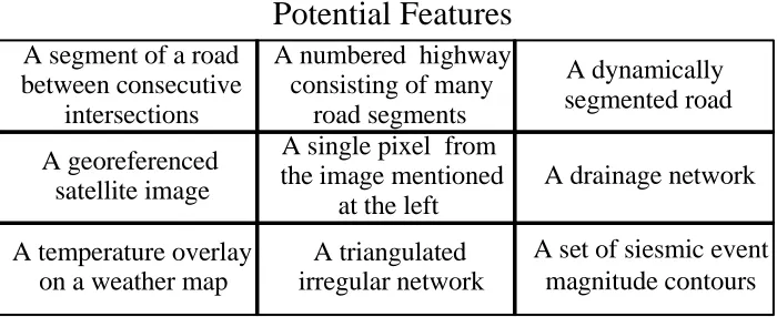
The fundamental unit of geospatial information is called a feature. Features may be defined recursively, so there can be considerable variation in feature granularity. For example, depending on the application or interests of the information gatherer, any of the items in Figure 2-1 could be a feature.
Potential Features
A segment of a road
between consecutive
A single pixel from
the image mentioned
A set of siesmic event
magnitude contours
Figure 2-1: Example Features
The collection and use of geospatial information has one purpose: to communicate knowledge about phenomena that have location. For example, the knowledge imparted by the map answers two kinds of questions: "where" and "what." Maps can tell us where things are, both in relation to other nearby things. Maps also can tell us what things are, either through symbology (e.g., by use of color or line pattern whose meaning is explained in a legend) or through text or tabular annotations or multi-media links. The same goes for attributes that modify or extend our knowledge of things.
Digital geospatial information is geospatial information that has been encoded into a digital form. The encoding is done so that computer resources can be applied to automate the business of geospatial information processing: storage, transmission, analysis, visualization and so forth.
This Abstract Specification exists to help bring order to this chaos and to provide the foundation model upon which the OGC standards are based.
2.2.
Introduction to the Notion of a Information Community
Typically, geographic features – such as “road” - are defined in the context of an Information Community. Broadly speaking, an Information Community (IC) is a collection of systems or individuals who share a common understanding of information and processes for their specific domain. This implies that the members of the information community share common understanding of their domain world, including definitions, vocabularies, interests, mutual awareness, and common technology sufficiently that they have the potential – and perhaps the capability - to share and use the information. For example, a state Department of Transportation is an Information Community. Any given DoT has a shared agreement on how they define any geographic feature within their IC, such the definition and semantics for a feature type “road”.
Information sharing between two individuals not belonging to the same information community is usually impeded by any of three conditions.
1. Ignorance of the existence of information outside one’s own information community.
2. Modeling of phenomena not of mutual interest.
3. Modeling of phenomena in two representations different from each other such that each is not recognized by the other.
The third condition is very, very typical in the geospatial community. Continuing our example of roads, different Departments of Transportation (different information communities) define and collect road features differently. The result is that a State boundary, a road may have different names, different semantics, different accuracy metadata and so forth.
The OGC provides a forum for enabling ICs to articulate and discuss their domain of interest. This is critical. A key aspect of interoperability is for one or more information communities to interact and drive to consensus for a common understanding (vocabulary and semantics) for their information domain. These information models define feature types and their properties. The goal to is define an information model for their
community. Technology is then deployed that uses the information model. For example, in the US, each state DOT is essentially an independent information domain with their own processes, policies, funding sources, etc. Even so, if we are to address broader interoperability issues, such as cross state sharing of transportation data, the State DoTs need to collaborate and define a common information model.
This document explores how an IC can formalize and unify its information-theoretic foundations to ensure that information sharing within its community is straightforward. As we will see, the process of formalization of information models for a community actually benefits communication between widely separated ICs, because it exposes the semantics of specialists within each community in a structured way.
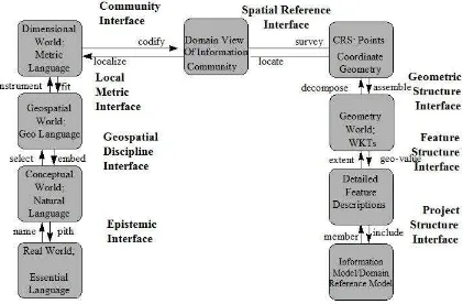
Following we discuss several levels of abstraction implicit when modeling real-world facts to create information models.
Figure 2-2: Nine Layers of Abstraction
We will discuss the nine layers one at a time. The first five layers, from the Real World to the Project World, deal with the abstraction of real world facts, and are not modeled in software. The final four layers, from Points to Feature Collections, deal with
mathematical and symbolic models of the world and are meant to be modeled in
software. Even so, this Essential Model of the final four layers assumes that they are real-world objects, and gives no specification, however abstract, for their implementation. The final layer is the abstraction of reality specified in the language an information – the geometric and semantic description of a set of features or Feature Collection.
2.3.
The Real World
Figure 2-3: The Real World
Figure 2-4 is an abstraction of Figure 2-3, using the Syntropy notation of [Cook94]. An object type is represented by a rectangle, with a name at the top of the rectangle.
Real World
Figure 2-4: The Real World Object Type
Figure 2-4 is an essential model in the sense of [Cook94], that is, it is intended to help understand a situation. The situation is the first step toward abstracting a part of the real world into feature collections. Along the way, we will refine the concept of a Information Community for geospatial feature collections.
Human discourse does not take place at the Real World level. Instead, humans give names to things (abstract them) and communicate with each other using these names. This naming process is exactly the method by which one interfaces to the next level of abstraction: the name method. The names are the proper and common nouns and pronouns of our natural language, and they are the language of the Conceptual World.
2.4.
The Conceptual World
Figure 2-5: The Conceptual World
The Conceptual World of our natural language is not sufficiently abstract for information modeling of geospatial features. In most Geospatial Technology Systems, only a
simplified subset of the Conceptual World is of interest. This subset is called the
Geospatial World. The method by which one interfaces to the Conceptual World is select.
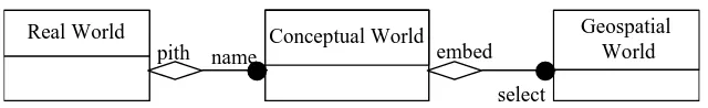
Geospatial World Real World Conceptual World
name
pith embed
select
Figure 2-6: Associations between the Real World and the Geospatial World
In Figure 2-6 there are three object types, each represented by a rectangle, and each with a name at the top. Lines between the rectangles represent associations between objects, and each of these carries a role name at each end to explain the association. The diamond represents aggregation; for example, the existence of the Conceptual World depends on the existence of the Real World. The solid circle means there is a set (instead of a single object) at that end of the association. For example, each Conceptual World embeds a set of distinct Geospatial Worlds.
2.5.
The Geospatial World
Practitioners of geospatial technology are used to thinking of the world in an abstraction that is almost cartoon in character. This is because the world, even at the conceptual level, is too full of complex shapes, patterns, details, and change to model realistically. These complexities are eliminated in the Geospatial World, and replaced with
abstractions that are usually temporally and spatially static as well. Please note, however, that an increasing number of applications are utilizing dynamic abstractions.
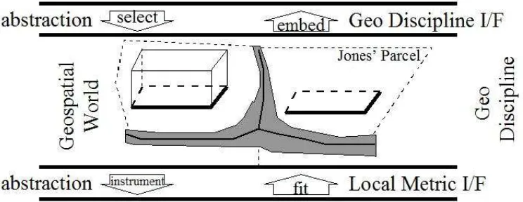
The language spoken in the Geospatial World is that of the “Geospatial Discipline.” In our example, the footprints of the houses remain, even that part of the footprint that was hidden behind another feature in a particular conceptual view. That is, from a typical GIS point of view, the full footprint of a building is “seen”, even when some of it is not in view. Each geospatial technology implementation has rules that specify what features are recognized in its Geospatial World, and how they are simplified from the Conceptual World. For example, there may be a rule that a brick house is simplified to a
3-dimensional polyhedron, while a house with another surface material is simplified to its footprint polygon. Similarly, facts that were not visible (but which were a part of the conceptual model) in the Conceptual World view become obvious in the Geospatial World, such as the street centerline and property boundaries, because these facts are of special interest within the GIS discipline.
Figure 2-7: The Geospatial World
The interface between the Conceptual World and the Geospatial World is called the Geospatial Discipline Interface. The method on this interface from the Conceptual World is called select. To traverse this interface in from the Geospatial World to the Conceptual World, one may invoke the method embed. The embed method places an item of domain interest into its proper context in the conceptual world.
Euclidean metric space that is assumed to exist (at least locally) throughout the Geospatial World.
2.6.
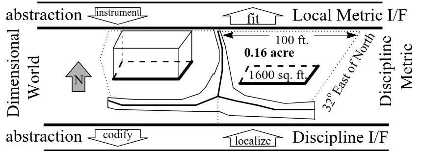
The Dimensional World
The Dimensional World is an abstraction of the Geospatial World where we become equipped with measuring tools such as tape measure, theodolites, GPS, and/or compass. The facts that are recognized at this level of abstraction include unary relations (such as length of an arc, and bearing of a horizontal line) and binary relations (such as distance between two points, buffer zone, and the “contains” relation) that are abstractions of the features themselves. Other examples include North, overlap, touch, dimensionality, intersect, and so forth.
abstraction
localize
Discipline I/F
Figure 2-8: The Dimensional World
The method by which the Dimensional World interfaces to the Geospatial World is called
fit. A distance between two telephone poles is a fact that belongs to the Dimensional
World. A wire of this length fits the span between them as seen in the Geospatial World. We include in Figure 2-8 some of the abstractions that are present in the Dimensional World.
The Dimensional World is the last of the “generic geospatial” abstractions of the Real World. The next abstraction is called a Domain World (some authors use the term “World View” with a similar meaning) that occurs only in the context of an actual domain implementation. Each implementation is specific to a particular discipline or sub-discipline (or a combination of a few of them). In each actual implementation, only a subset of the Dimensional World is recognized. Often, the subset is determined by map neat lines and by the particular phenomena that have been instrumented.
construction), “knots” (for NURB construction), “center” (for circle construction), and so forth.
The interface between the Dimensional World and the Project World is called the Community Interface. The method for invoking the Community Interface from a feature in the Dimensional World is called codify, and results in a coordinate system being invoked in terms of which all the features’ corners can be abstracted as an n-tuple (n is usually 2 or 3) or into an equivalent abstraction. Conversely, a feature with known coordinates in the Project World can invoke the localize interface to result in the feature’s proper placement relative to other features in the Dimensional World, and with
appropriate measurements.
2.7.
The Project World (or The “World View”)
2.7.1.Introduction to the Modeling of Geospatial Features
There are three popular approaches for the modeling of geospatial features. The first models the spatial extent of a feature with point, lines, polygons, and other geometric primitives that come from a list of well-known types. Features modeled in this fashion are called “Features with Geometry.”
The second approach is called a “Feature as Coverage”. This technology includes images as a special case.
The third approach is “Feature as Observation”. An Observation is an action with a result which has a value describing some phenomenon. The observation is modelled as a Feature within the context of the General Feature Model [ISO 19101, ISO 19109]. An observation feature binds a result to a feature of interest, upon which the observation was made. The observed property is a property of the feature of interest.
All these primary Features types are intimately related, yet have distinct concepts This specification will complete the nine layers of abstraction for the case of Features with Geometry. The notion of Coverages is introduced and compared to Features with Geometry in Section 2.13.
2.7.2.Introduction to the Project World from the “Feature With Geometry” Point of View
The use requirements of geospatial content for an information community always reflect the specific discipline or disciplines of their owners. Examples of geospatial disciplines in which geospatial abstractions are frequently found include forest management, soil mapping, cadastre management, base cartography, surface hydrology, wetlands,
transportation modeling, and so forth. Each of these disciplines has many sub-disciplines, and an information community can involve any combination of these.
It is exactly the multiplicity of languages at the Project World level that leads to the most difficult problems in interoperability between geospatial information stores. This is the source of much of the splintering that artificially divides the Geospatial World. The situation is manageable, however, if sufficient care is taken in the formalization of the language constructs. We will see that each Geospatial Information Community is intimately related to an equivalence class in the set of all possible Project Worlds under a special relation.
x
Figure 2-9: The Project World, or The World View
Using the Syntropy notation, the associations from the Geospatial World to the Project World are represented in Figure 2-10.
Geospatial
Figure 2-10: Navigation between the Geospatial World and the Project World.
To give the next four levels of abstraction sufficient rigor for unambiguous representation in software, we insist on imposing a great deal of structure upon the language of the Project World (which we call the Information Community Language.) It is through these structures that individuals certify that they are observing common phenomena, and have abstracted the Real World in a repeatable way. Specifically, we impose nine formal and rigorous structures: Feature Instances, Geometry, Coordinates, Geometry Schema, Coordinate Reference System, Feature Types, Attribute-Value Pairs, Attribute Schema, and Project Schema. All of these are to be understood as real world facts, not to be modeled in software at this level of abstraction. We forbid all language that lies outside these structures. Because all nine structures are essential for information sharing, we will discuss each of them, one at a time.
2.7.3.Project World Feature Instances
The primary structure we impose on the Project World in that of the feature. The Project World is completely defined by the instances of the phenomena it recognizes: features. This specification is intended to enable the geospatial engineer to conceptualize and model features in a manner appropriate to the task at hand, and does prejudice the engineer with predefined thematic classes. This specification is standardizing geometric classes, but does not assume that two engineers will apply them identically to model the same information.
The features of the Project World carry less, but more structured, information than was held at the Geospatial World level, through the process of abstraction and simplification. To make the Project World definitive, we demand that the rules for the inclusion of features from the Geospatial World into the Project World be explicit. Such rules are often called “capture criteria,” or “instance conditions.” Each instance of a feature in the Project World fits a category in the capture criteria.
2.7.4.Project World Feature Types
The categories of features captured in a Project World are feature types. Each feature type can be thought of as a “template” to be populated at each occasion of a feature instance corresponding to that type. The template is populated with information specific to the feature instance. More details are at Section 2.7.8.
2.7.5.Project World Geometry
The feature of the Project World is a simplification and abstraction of the cartoon information carried in the Geospatial World. We recommend that features with spatial extent in the Project World be conceptualized using simple primitive geometric shapes. For interoperability, we recommend that the primitive shapes be instances of the Well-Known-Types (WKTs) of geometry, such as polygons, line strings, polyhedrons, and other shapes. The current enumeration of geometry types can be found in the OGC Abstract Specification Topic Volume 5 (also ISO 19107 – Features). We call instances of WKTs Well-Known-Structures (WKSs). We further demand that rules for representing each feature type with WKTs is explicit (for example, a rule may specify that a brick house is seen as a polyhedron.) Finally, we demand that the conceptual model of the WKSs carries sufficient information to enable the reconstruction of the extents of the features to which they contribute. That is, we insist that the geometry components “know” how they contribute to complex geometries (for example, the highway segment geometries must know the sequence in which they concatenate to become an entire highway feature.
2.7.6.Project World Envelope
The primitive spatial concept in a Project World, from which all phenomena with spatial extent are spatially conceptualized, is “envelope”. An envelope is a geometric primitive that (directly or indirectly through a geometric construct, such as a spline) defines (in whole or in part) the spatial extent of one or more of the phenomena recognized within the Project World.
Each OGC WKS can be constructed from a finite set of points that are its corners. We strongly recommend that the corners of an envelope be explicit in the Project World. We further demand that the model for the envelope carries sufficient information to allow for the construction of the WKSs. For example, we recommend that the sequencing of envelope along a polyline is explicitly available within the Project World.
2.7.7.Project World Geometry Schema
The collection of rules implicit in sections 2.7.5 and 2.7.6 are called the geometry schema of the Project World. Examples include:
•
for each feature type, the geometry WKTs that are to be used in its representation•
for each WKS, the feature instances to which it contributes•
for each feature instance, the WKSs that contribute to its extent•
for each WKS, the structured list of corners which specify it•
for each corner of an envelope, the WKSs to which it contributesWe introduced the notion of a Coordinate reference System at the end of Section 2.6. Here, as there, we are treating a Coordinate reference System as a real world fact. A good example is a well-monumented beginning used by a surveyor. The point-of-beginning, together with the tools and rules for surveying, enable one to attach
coordinates to every point of interest in a project. The points of interest are precisely the coordinates needed for the geometric construction of the geospatial extent of any feature recognized by the project.
Because the introduction of a Coordinate reference System is central to the notion of a project world, the methods for traversing the Community Interface between the Dimensional World and the Project World are named for the actions relating to it. Invoking the method codify causes points in the Dimensional World to obtain their Coordinate reference System coordinates or parameters. Invoking the method localize removes the coordinates and recovers points in correct relative positions.
A detailed model for Spatial Referencing by Coordinates can be found in ISO 19111, OGC Abstract Specification Topic Volume 2.
2.7.9.Project World Attribute-Value Pairs
Section 2.7.3 began by insisting that the Project World recognize only features. This section puts additional structure on the concept of feature. We are going to replace our rich and complex natural language descriptions of features with an abstracted stick-figure language of attribute-value pairs.
So far, each Project World feature is associated with two structures: the feature type of which it is an instance, and the geometry consisting of an OGC WKS. The geometry is expressed relative to a Coordinate Reference Systems, and includes all coordinates needed for its construction. We now additionally insist that each feature instance be described using a strict grammar and vocabulary. The purpose of the grammar and vocabulary is to unambiguously and in a repeatable manner describe the attributes of interest for each feature within the Project World.
In the Project World, each feature type is associated with a list of attributes. Our grammar demands that each attribute in the list have a formal attribute name, and that each
Figure 2-11: Template for [AttributeName /Value Type] Pairs for Feature Type: RoadSegment
Our vocabulary, therefore, is quite limited. We are allowed only the following terms: 1.the names of the feature types recognized by the Project World
2.attribute names 3.attribute values.
Of course, each of these terms can be used only where our grammar permits.
Every feature may publish a unique, persistent. Most feature types have an attribute that can take geometry values. This is the attribute whose value is the WKS that models the physical extent of a feature instance of this type. Relationships between features may not be carried as an attribute-value pair, but must use the facilities described in Topic 8: Relationships Between Features.
2.7.10.Project World Attribute Schema and Feature Schema
The collection of all feature types recognized by a Project World (including the capture criterion for that feature type) together with the list of Attribute/ValueType pairs for each one, is the attribute schema of that Project World.
x
Figure 2-12: Another look at the Project World
The attribute and geometry schemas constitute the feature schema of the Project World. See Figure 2-12.
Figure 2-12 is a refinement of Figure 2-9. It explicitly includes the feature schema as a part of the Project World.
names and meanings of its attributes, as well as the meaning (to include types and units) of its values.
This implies the existence of a dictionary in each Project World where the semantics of the terms in the vocabulary are made clear. The semantics are usually explained in a natural language, with many examples, and have many more dimensions than indicated in this paper. The semantics include aspects of: feature definition, classification
discriminators, accuracy, sources, methods, intended uses, and so forth.
2.7.11.Project Schema
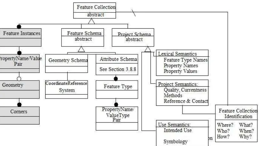
The OGC is, to a large extent, about enabling commerce in geospatial information and process. We make the basic assumption that an important unit of trade in this commerce is a feature collection. Each distinct and unique feature collection, therefore, needs to carry enough meta-information to allow the feature information it carries to be
understood and exploited. We hinted at some of this meta-information when we spoke of a dictionary for the Project World vocabulary, but there is more. The Project Schema is the formalization of this meta-information, and it is best defined in the Project World context. Figure 2-13 shows the relationships between a feature collection, its features, and the meta-information needed for commerce. The shaded object types denote information that supports the modeling of feature instances within the feature collection. The white object types all hold meta-information of some kind. The white objects, collectively, are termed metadata. We have already introduced the Feature Schema; it is simply the union of the Geometry Schema (See Section 2.7.7) and the Attribute Schema (See Section 2.7.10).
The Project Schema consists of four parts: 1.Feature Collection Identification 2.Lexical Semantics
3.Project Semantics 4.Use Semantics.
We will briefly explain each of these objects, below.
The Feature Collection Identification is a simplified selection from the Project Semantics that is designed to be queryable. For now, it suffices to say that this object provides a unique identifier to the Feature Collection, and provides a high-level description of it: Where: the region of the Earth covered
What: the approximate scale, the thematic key words
Who: the responsible agent, instructions for access to the Feature Collection When: the date the data was created and the date of its sources
How: the method to acquire the feature data Why: the intended use
We will see that the Feature Collection Identification (metadata) is used to support discovery. Since the Feature Collection Identification often plays a role that makes it seem to be intimately connected to the Feature Collection itself, we show a derived relationship between these two object types.
Lexical Semantics are basically the dictionary of terms used in the attribute schema. The Lexical Semantics must provide sufficiently rich definitions and enough examples that there be no ambiguity concerning the proper schema for each feature instance. Project Semantics describe how the Project World was conceptualized, and how the Feature Collection was generated. Included here is the physical extent of the project, such as the map neatlines, or the region imaged from a space platform.
Use Semantics provide details on how to exploit the feature collection. Included are the intended uses for the information as it was collected, any indices that improve access to the information,
Figure 2-14: A Final Look at the Project World and Its Fundamental Schema
We now have the tools with which to define a Geospatial Information Community. But first let us complete the process of abstracting to features and feature collections.
2.8.
The Point World
Each Project World has a project-wide coordinate reference system. With the coordinate reference system, we are able to interface to the next level of abstraction: the Point World. The Point World is perhaps best imagined as Cartesian space populated with a finite collection of special points. Starting from any coordinate of any feature in the Project World, we assume a method named survey that abstracts the coordinates of the corner to arrive at a special point in the Point World. Conversely, for each special point in the Point World we assume a method named locate that locates that point as a coordinate of a feature in the Project World. Of course, the survey and locate methods work for points other than the feature coordinates, but to recognize these additional points, one must enlarge the schema and allow new phenomena to be recognized.
survey
locate
x
y
u
v
abstraction
OpenGI
S Point World
Section 314
Coordinate
Geom
etr
y
Spatial Reference I/F
φ=45ο
(x1,y1)
(φ1,λ1,h1)
(u1,v1)
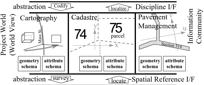
Figure 2-15: Point World
Figure 2-15 represents the situation. There are three Point Worlds represented: one each for cartography, cadastre, and pavement management. Each Point World consists of a coordinate reference system together with a finite set of points (which are at the coordinates of geometries representing features of interest to those three specialties.)
P o i n t W o r l d P r o j e c t W o r l d
o r W o r l d V i e w
s u r v e y l o c a t e
C o o r d i n a t e R e f e r e n c e
S y s t e m
H o r i z o n t a l D a t u m V e r t i c a l D a t u m
Figure 2-16: The Abstraction of Points from the Project World
Using the notation of [Cook94], the situation is represented in Figure 2-16, where an attribute of an association is shown attached to the association line with an oval. The association of a coordinate in the Project World to a coordinate pair (or n-tuple) in the Point World has an attribute called the Coordinate Reference System. Perhaps more properly, there is an association type that specifies the structure of the association with additional information, including the horizontal and vertical datums. (A horizontal datum, in this setting, may be taken to be an unambiguous assignment of longitude and latitude values to real world locations in a manner that agrees with observations of lengths and angles. A vertical datum similarly assigns elevations to locations.)
2.9.
The Geometry World
Figure 2-17: The OGC Geometry World
Figure 2-17 shows some representations of the Geometry World, which is populated with points, polygons, polyhedra, and so forth, all in the context of an abstract coordinate system.
The role of the geometry schema is shown more explicitly in Figure 2-18. Here we see that the association between the Point World and the Geometry World is actually a derived association (as indicated by the diagonal line on the association line.) The navigation path from Points to Geometries is through the geometry schema captured in the Project World abstraction.
Figure 2-18: Navigation From Points to Geometry
We also show a derived association between the Coordinate Reference System and the Geometry Schema. This is to indicate that the Coordinate Reference System often seems to behave as if it operates on complete geometries, and not just on coordinates.
In Figure 2-18 we used the geometry schema to build the Geometry. Next, we will use the attribute schema to build Features.
2.10.
The Feature World
At the level of an Essential Model, each Feature type is specified by its attribute set. An attribute set is a list of attribute/value pairs that is applied to all features of the
corresponding type. Every feature instance in the Project World belongs to the one of the recognized types. The type specifies the list of attributes that distinguish the feature, as specified by the Attribute Schema. Most geospatial features have an attribute called “Geometry,” (or, “[FeatureTypeName]Geometry”) and, if so, its value must be the OGC WKS that was conceptualized in the Geometry Schema. Figure 2-19 is a representation of the situation.
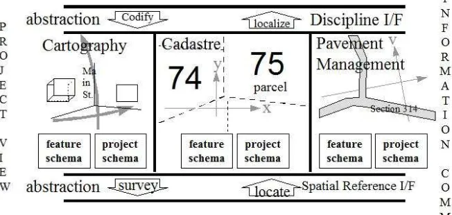
Figure 2-19: The Feature View
Figure 2-19 shows a typical feature in each of the cartographic, cadastre, and pavement management domains. These features did not suddenly come to exist for the first time in the Feature World. The features are the same ones formulated in the Project World. There are two chief components to an feature: its attribute schema, and its geometry. Figure 2-20 shows how the two components of the feature come together.
Figure 2-20: Navigation Near a Feature
Notice that the association between Geometry and Feature has no slanted line on it. This is in recognition that this is not a derived association, but rather the primary navigation path for geometry. The path from the Project World to the Feature does not carry geometry, but it does carry all the rest of the Feature Schema.
The interface between the Geometry World and the Feature World is the Feature Structure Interface. It is traversed by the extent and geometry-value (or geo-value, for short) methods. These methods are clear: the extent of a feature is the space it occupies, and this is modeled by an OGC WKS. Likewise, every feature with extent has an attribute named geometry, whose value (that is, the geo-value) comes from the Geometry World.
The interface between the Project World and the Feature World is called the Attribute Schema Interface. It is traversed by transparent methods named attribute and instance. There are two new object types in Figure 2-20: Attribute and Attribute Reference System. By “Attribute” we mean a (AttributeName, ValueType) pair, as defined in Section 2.7.9, and as spelled out in the Attribute Schema. The Attribute Reference System is
(sometimes) needed to give meaning to the attribute value. For example, a feature may be a temperature coverage defined by a triangulated irregular network (TIN) from a finite number of temperature samples. The mechanics of returning a temperature at a specified point (a coordinate perhaps not in the finite set of coordinates with temperatures) is accomplished by the Attribute Reference System.
Refer also to Appendix B. The ISO TC211 General Feature Model for a similar representation of features, their attributes, functions and relationships.
2.10.1.Feature Collections
An Feature Collection is an abstract object consisting of Feature Instances, their Feature Schema, and Project Schema. Figure 2-21 shows Feature Collections in a Syntropy diagram.
Figure 2-21 Navigation Near the Feature Collection World
Figure 2-21 can be simplified by collapsing the Geometry Schema and the Attribute Schema into the Feature Schema. Doing this yields Figure 2-22.
OGIS Features
Figure 2-22 Feature Collections Consist of Features, their Feature Schema, and a Project Schema
2.10.2.Interfaces on Feature Collections
The interface between the Feature Collection World and the Feature World is called the Project Structure Interface. This interface is transparent, but it is derived from paths through the Project World. This is because the members of the Feature Collection World correspond directly to phenomenon in the Project World, not to a feature in the Feature World. Nevertheless, the methods across the Project Structure Interface, called member and include, are obvious.
The interface between the Feature Collection World and the Project World is called the Project Schema Interface. Its methods are also obvious, and are called realize and
represent.
2.10.3.Background Notes on Feature Collections
The Open GIS Consortium has not yet achieved consensus on many issues surrounding Feature Collections. On the one hand, perhaps Feature Collections are not needed at all. This is because:
•
a feature can be a composite of other features, connected by relationships of a particular type (see Topic 8)•
a “tile” may be a feature composed of (related to) the features it contains•
a feature may have one of its geometry values “divided” by tile boundaries, and thus be split into one feature with two geometry values or two features each with part of the geometry, yet need to be “reassembled” on demand by an interface on Feature or by a service.On the other hand, the real world seems full of Feature Collections that need to be addressed. These include:
•
projects, which have assignment boundaries and feature capture criteria and thresholds•
products from Government agencies, such as VPF, ADRG, SDTS, ATKIS, and similar files•
GIS database filesFeature Collections seem to need important interfaces in order to support the needs of Catalogs and Catalog Services. These interfaces seem to be tightly coupled with Feature Collection Metadata. Formal definition of feature identifier scope is required, and every scope implicitly has an association with the collection of features whose identifiers it can resolve.
2.11.
Summary of the Nine Layer Model
As a summary of the preceding sections, and as a reformulation of Figure 2-2, we present Figure 2-23.
Using the notation of [1], we present Figure 2-23.
Figure 2-24 The Object Types of the Nine Layer Model
2.12.
An Alternative Perspective to the Nine Layer Model
Figure 2-25 Conceptual Model of the ‘Real World’ modelling process
2.13.
Persistent Feature Identifiers
2.13.1.Problem Statement
Managers of complex geographic information systems require capabilities for incremental update, distributed update, copying and partially modifying data. These capabilities require a more careful examination of the issue of feature identity than has previously been achieved.
Identity has implementation, logical, syntactic and philosophical aspects. A complete analysis is not attempted here.
Some handling of feature identifiers is necessary in order to represent relationships between features. This is discussed in Topic 8 of the Abstract Specification A troublesome issue in the community is the lack of ability to support value-added information in a cost-effective manner [Hair97]. Value added information is an extension of a primary database which needs persistent feature identifiers in order to allow:
•
additional information to a base dataset is required for a one-off or transient application•
a base of information exists but there is a long term need for additional information that has not been captured in the pastformation that has not been captured in the past
•
partnerships are established based on areas of expertise but sharing some common data, e.g. between telecommunications and electricity utility companies•
partnerships are established based on areas of expertise but sharing some common data, e.g. between telecommunications and electricity utility companies•
incremental updating and incremental publishing•
incremental updating and incremental publishing•
maintenance of complex or aggregate objects (currently using relationships, see Topic 8).•
maintenance of complex or aggregate objects (currently using relationships, see Topic 8).Natural Language (e.g. English) Human Experience Formal Languages (Mathematics, Logic, Specification
•
Reference to a geographic feature within a repository from outside the repository and perhaps outside any computing system, e.g. as a string of text in a hand-written letter.We also need persistent, immutable feature identifiers in order to support:
•
Tracking of feature identity during updates and collaborative working•
Proper management of versions•
Lineages of data transformationsThe differences between geographic feature identifiers and many other types of persistent identifiers are of scope and scale. A single geospatial data repository may contain hundreds of millions of features. CORBA Persistent Object Identifiers are intended to identify executing software objects in much smaller numbers. Similarly, the IETF Unified Resource Names are designed for smaller numbers of objects. However, the design of IETF URNs may be appropriate for geographic features even if current implementations of identifier resolvers may not be [URNDNS].
2.14.
Resolving Scoped Feature Identifiers
2.14.1.Fundamental Ideas
Every feature has one feature identifier (name) within its immediate scope (namespace). A feature identifier is persistent and immutable.
A namespace, a "Scope", in which an identifier can be resolved, is itself a software object and does itself require a permanent identifier.
Scopes can be nested, but do not form a strict tree: a directed acyclic graph (DAG) is possible.
At the "bottom" are the leaf-objects, which are explicit identifiers which do not then need resolving in any other scope.
At the "top" we need to have some "Well Known Scopes" written into the implementation specification.
Leaf objects can be feature identifiers, scope identifiers, or any other type of identifier. We just deal with feature and scope identifiers here. Note that we only deal with identifiers.
Using a fully-resolved "bottom" leaf feature identifier to actually retrieve a feature's data is access not resolution and is a different issue.
2.14.2.Key concept
Scope is a permanent object with a persistent, immutable name that allows it to be located indefinitely, which can answer queries about identifiers "in its scope": resolving them to more explicit identifiers.
Finding a "scope object" is thus necessary. CORBA POAs and IETF URNs would be appropriate for the identifiers of scope objects.
2.14.3.Key supporting concept
Any scoped identifier (simply called an "identifier" or "name") is conceptually and perhaps actually constructed in two parts:
•
A prefix, which defines the scope in which the suffix has meaning.There is also always a third, invisible, part: the scope in which the whole thing, prefix and suffix, should be interpreted. This is because an identifier is always "inside" a scope.
2.14.4.Principles
Longevity, delegation and independence [URNres]. Identifiers must be persistent (last a long time)
It must be possible to delegate both authority and responsibility for both naming and resolution
The various delegations must be capable of being independent of one another
There are three aspects to naming: identification, location and mnemonics (semantics) [URIres].
The resolution system must be separate from the way identifiers are assigned [URNDNS]. This separation allows multiple naming approaches and resolution approaches to interact and to compete.
These identifiers are generally distinct from Human Readable Names (HRNs). However, a Scope can be defined in which identifiers are Human Readable, and then HRNs can be resolved in the same way as any other scoped identifier.
We need to be able to "grandfather in" existing naming schemes and Scopes [URNDNS]. Resolver services must be able to support scaling in three dimensions: number of
features, number of data publishers, and complexity of delegation [URIres] "One cannot make global, systemic guarantees except at an expense beyond reason."
[URIres].
Scoped Identifier
Resolution request
Identifier
Enclosing scope
Sub-scope Resolution result
2.14.5.Resolver Services
Resolvers and similar systems can offer several services. The following list is taken from IETF work which use the term "name" for "identifier", "namespace" for "scope", and "characteristics" for "metadata" [URNDNS]:
N2L Given a name (identifier), return a location (URL) N2Ls Given a name (identifier), return a set of locations
(URLs)
N2R Given a name (identifier), return the feature ("resource") itself
N2Rs Given a name (identifier), return multiple instances of the feature ("resource")
N2C Given a name (identifier), return its characteristics (metadata), e.g. a URC. Characteristics are always potentially a list (plural).
N2Ns Given a name (identifier), return all the names that are identifiers for that feature
N=N? Are these two names identifying the same feature? L2R Given a location (URL), return the feature
("resource")
L2Ns Given a location (URL), return the names that identify that location
L2Ls Given a location (URL), return a list of locations that contain the same feature
L2C Given a location (URL), return its characteristics (metadata), e.g. a URC.
L=L? Are these two locations the same?
R=R? Are these two features the same? (Assuming they have different names)
Figure 2-27 Resolver Services
Notes for Figure 2-27:
•
Using the above naming convention, "C2N" would be a metadata query, not a resolver query.•
N2C, even at the "lowest" level scope, is often all that can be achieved if the "resource" is off-line or in hard-copy form only.•
For the purposes of feature identification, we need all scoped identifier resolvers to offer only the following service: the critical service N2Ns (which we expect usually to return a single new name in a "lower" scope).•
For the purposes of feature identification, we need the "lowest" scoped identifier resolvers to offer only the following services: N2R, or N2Rs, and/or N2C as appropriate.preferable to set up an architecture whereby new services could be registered, discovered and advertised. This is the approach which will eventually be followed by IETF [URIres], but at present such an approach would be premature.
2.14.6.Further Example
"The Handle System®" from CNRI is an example of a 1-level scope system. An identifier looks like this:
hdl://cnri.test/abcd/efg/ijk#123
Where:
•
the suffix is: abcd/efg/ijk#123•
the prefix is: hdl://cnri-test/•
and the scope in which it makes sense as an identifier is The Handle System® which exists in within the Internet.The Handle System includes a large number of scopes, but all of them have “hdl://”as the first part of their prefix.
2.14.7.Hints
The above example illustrates another useful but non-essential characteristic: the invisible scope in which the identifier should be resolved is indicated in a non-formal way, a "hint" URNres] by the initial part of the text string of the prefix. Any informed person reading “hdl://” has a pretty good idea that we are dealing with a variety of URL (a URI to be pedantic [URI]) and we need to find which protocol “hdl:” represents. This capability is most use at the "top" level when we have to decide which Well Known Scope we have to start with. Lower scopes could be pure binary for prefixes and suffixes.
Hints are much more general facility than simply being an interpretation on prefixes; they are "anything that helps in the resolution of an identifier" [URNres]. Hints may
themselves have metadata attached to them and may be an intermediate step in the resolution of an identifier. However they are also only hints: they may be out of date, temporarily invalid etc.
2.14.8.Well Known Scopes and URNs
A Well Known Scope is a Scope Environment, e.g. X.500, Corba Locator Service, DNS (machine identifiers), URL (file identifiers if the location is permanent).
Other Scope Environments might be:
•
a FeatureCollection•
a database•
a computer•
a geodata repository service•
a website•
URNs2.14.9.Uniform Resource Names
A URN always has the following syntax: urn:<NID>:<NSS>
(i.e., urn:<namespace>:<suffixname-which-can-contain-colons> ) The standard names are NID and NSS: NID is the namespace identifier (scope identifier) and NSS is the namespace-specific string [URNres].
Thus the "invisible", third, enclosing scope for a URN is always visible because all URNs begin with the same literal string "urn:"
NSSs are expected to be partitioned into delegated and subdelegated namespaces where the delegated namespaces are free to choose their own syntax for the variable part of the namespace [URNres].
URNs can have access controls applied to their resolution.
If a scoped identifier is a Uniform Resource Name or URN [URN], there is a proposed mechanism already whereby resolvers for those names can be located using DNS [URNDNS] and HTTP [URNhttp]
The "hint" to find a resolver can be encoded in a rewrite rule inside Domain Name Servers [URNDNS]. Replicated repositories and resolvers can be supported by this means.
URNs are a specific design of scopes which can be arranged in nested scopes in a directed acyclic graph.
URNs need not include the more-resolved scoped identifiers lexically in the successive suffix parts (opaque or not), and they can support rewrite rules which enable automatic grammar-directed mapping between names (identifiers) in one namespace (scope) and another namespace.
Every resolution of an identifier (name) occurs in URN resolvers, possibly even in the same resolver software running on the same machine, but the path of resolution can trace out a directed .acyclic graph.
URNs already have had preliminary studies made on their security and privacy [URNres].
2.14.10.What resolution does
An identifier is resolved by giving it to the Scope object in which it is defined (the invisible one), which (conceptually) strips off the prefix, finds the Scope object that the prefix names, and hands the suffix to that Scope object. When the process reaches a leaf identifier, the stack unwinds and the leaf identifier is returned together with whatever information is necessary for the original enquirer to make use of it. This is a sequence on N2N operations.
2.14.11.Resolution, discovery and access
For software specification it is best to keep orthogonal functions specified entirely separately as distinct interfaces. Any implementation may choose to support one or several interfaces. We have three quite separate specifications to think about:
•
Issuing or assigning scoped identifiers•
Resolving scoped identifiers N2N•
Accessing data (data repository query), N2RExperience with these types of systems has produced a major principle: that the resolution system must be separate from the way identifiers are assigned [URNDNS].
2.14.12.Handles and descriptors
We understand a feature descriptor to be something which is resolved by a Catalog Service. A feature descriptor contains "sufficiently unique metadata".
This discussion of scoped identifiers covers what we previously called a feature handle.
2.14.13.Permanent scope objects
Anything could offer an identifier resolution service within an "understood" scope, but we need to ensure that scoped-identifiers are only issued containing scope object prefixes for scope objects with certain minimum required qualities of permanence and
immutability.
Catalog services are something which we could also cover by this same scoped identifier mechanism.
2.14.14.Uniqueness of identifiers
2.14.14.1.The same feature can be in several Scopes
There does not seem to be any way to avoid this since anyone can set up an identifier resolution service which then defines its own new scope.
Thus the same feature (a specific software representation of a real world object) can have several scoped identifiers. It will have the same leaf identifier (in the immediate scope of the feature), but this could appear in published form hidden inside several different scoped identifiers via different scopes.
Thus we lose equality by value for published identifiers; however we can define an equality method on identifiers if the method resolves them down to the lowest common denominator scope. Because scopes form a DAG not a tree, and because identifier length does not tell you anything about how many prefixes may be hidden inside opaque suffixes, it is impossible to tell how far down this is until the resolution is actually performed.
We need to make the following restriction:
2.14.14.2.An identifier cannot be a leaf in more than one scope
This is tricky, since data repositories can always be copied. So we need to think about how to define scopes for copies, and to consider replication possibilities to see if we can relax this condition under certain carefully-controlled circumstances.
2.14.15.Uniqueness and equality
The idea of equality is very specific to individual information communities. Often the same feature does require multiple names, even at the most fully-resolved level. The classic example is a weather map:
•
The map of 26 October 1998•
Today's weather mapBoth are useful names, and at some time they may both point to the same resource [URIres]. A resolver may support equality of feature R2R as well as equality of fully-resolved identifier N2N, but if it does it will do it in an opaque way.
All identifiers discussed in this background description are published, external identifiers. Any repository can use any internal identification mechanism it likes so long as it can support permanent, immutable external identifiers.
As an example, consider a system which uses 8-digit numbers as internal feature identifiers. Such as system might want to be able to represent foreign identifiers (e.g. to implement some feature-feature relationships) and it might do so by internally using identifiers of the form "9xxxxxxx". The initial "9" indicating an external identifier. Such a system would then have a bit of software in its export subsystem which published its own identifiers as scoped-identifiers and replaced the foreign identifiers with the original foreign scoped identifier (stored in some local registry).
The interesting thing about this example is that the initial "9" can itself be considered to be a scope-prefix inside the proprietary system. This illustrates the general points that
•
a scope "inside" another scope can actually be "larger" than the containing scope, and that•
a resolving service may only be able to cope with a subset of the identifiers which actually exist in a "sub"-scope.The important property of an identifier is that is resolvable, not that it is readable.
2.14.17.Scope aliases
Some scopes may exist only to provide short-forms of identifiers, e.g. in the above example a single digit "9" represented the entire outside world. A deeply-nested identifier could accumulate a very long string of prefixes, so within an organisation or information community, a scope resolver which provided short-form aliases could be useful.
Scopes can cross-reference each other, thus the opaque part of an X.500 scope may be a URN which resolves to a Handle System identifier.
2.14.18.Published identifiers
Any identifier published, e.g. in an email or quoted by some other piece of general purpose software for any value-adding purpose, must quote scope prefixes all the way back to the most-global Well Known Scope. This is where it is particularly useful if the prefixes understood by Well Known Scopes are not opaque but are readable as "hints". The examples of the hints "hdl://" and "urn:" have already been mentioned.
2.14.19.FeatureCollection
Conceptually, there exists a FeatureCollection of all the features whose identifiers are in the Scope, but
this FeatureCollection is not a Scope, neither is a Scope a FeatureCollection,
they are just implicitly associated. The FeatureCollection may not be instantiatable even in theory for some Scopes.
2.14.20.Methods of Feature Identity Scope
A Scope Object has these methods: