ACCURACY TEST OF MICROSOFT KINECT FOR HUMAN MORPHOLOGIC
MEASUREMENTS
B. Molnár *,a, C. K. Toth b, A. Detrekőia
a
Department of Photogrammetry and Geoinformatics
Budapest University of Technology and Economics, M
ű
egyetem rkp 3., Budapest, H-1111, Hungary -
[email protected]
b
The Center for Mapping, The Ohio State University
470 Hitchcock Hall, 2070 Neil Avenue, Columbus, OH 43210 - [email protected]
Commission TCs III and V
KEY WORDS: Flash LiDAR, MS Kinect, point cloud, accuracy
ABSTRACT:
The Microsoft Kinect sensor, a popular gaming console, is widely used in a large number of applications, including close-range 3D measurements. This low-end device is rather inexpensive compared to similar active imaging systems. The Kinect sensors include an RGB camera, an IR projector, an IR camera and an audio unit. The human morphologic measurements require high accuracy with fast data acquisition rate. To achieve the highest accuracy, the depth sensor and the RGB camera should be calibrated and co-registered to achieve high-quality 3D point cloud as well as optical imagery. Since this is a low-end sensor, developed for different purpose, the accuracy could be critical for 3D measurement-based applications. Therefore, two types of accuracy test are performed: (1) for describing the absolute accuracy, the ranging accuracy of the device in the range of 0.4 to 15 m should be estimated, and (2) the relative accuracy of points depending on the range should be characterized. For the accuracy investigation, a test field was created with two spheres, while the relative accuracy is described by sphere fitting performance and the distance estimation between the sphere center points. Some other factors can be also considered, such as the angle of incidence or the material used in these tests. The non-ambiguity range of the sensor is from 0.3 to 4 m, but, based on our experiences, it can be extended up to 20m. Obviously, this methodology raises some accuracy issues which make accuracy testing really important.
1. INTRODUCTION
The superior performance and efficiency have made laserscanning systems the primary source for 3D measurements. Main LiDAR methods are well explained by Shan and Toth (Shan and Toth, 2008). The two typical LiDAR platforms are airborne and terrestrial (TLS) laserscanning (Vosselman, 2010), though mobile LiDAR (MLS) is gaining rapid acceptance. These methods use pulsed-based technology with discrete return detection or waveform recording recently. For close range LiDAR scanning, Flash LiDAR is increasingly used. This technology is based on a sensor array, which makes it possible to measure multiple ranges at the same time. The range of the captured depth image is mainly limited based on the emitted impulse power. The frequency is also somewhat limited for eyesafety and technological reasons. For example the early Flash LiDAR model, the SWR3000 (Kahlmann et al., 2006) is based on CW approach, offering an operating range up to 7.5 m and a frame rate of 15 Hz. The newer PMD [vision] CamCube 2.0 has a range 0.4 to 7 m and 25 fps (PMD).
Successful facial reconstruction requires an appropriate model of the human face. Therefore, a wide range of data collection procedures have been developed, mostly based on photogrammetry (Schrott et al., 2008). Flash LiDAR is a good alternative for surface point gathering methods. In addition, it is fast data acquisition. The post processing and model creation, however, require some specific knowledge, as the human face has special surface conditions (Aoki et al., 2000). The developed model provides a good base for plastic surgery.
2. MICROSOFT KINECT SENSOR
The Kinect™ sensor is a motion sensing input device for the Xbox 360 video game console, originally developed by PrimeSense (PrimeSense), and acquired by Microsoft®. The primary purpose is to enable users to control and interact with the Xbox 360 through a natural user interface using gestures and spoken commands without the need to touch a game controller at all. The Kinect has three primary sensors: a Flash LiDAR (3D camera), a conventional optical RGB sensor (2D camera), and microphone array input. The device is USB-interfaced, similar to a webcam, and appears as a “black box” for the users.
Very little is known of the sensors, internal components and processing methods stored in the firmware. The laser, IR, emitter projects a structured light pattern of random points to support 3D recovery. The 2D camera can acquire standard VGA, 640x480, and SXGA, 1280x1024, images at 30 Hz. The color formation is based on Bayer filter solution, transmitted in 32-bit and formatted in the sRGB color space. The FOV of the 2D camera is 57° x 43°. The 3D camera can work in two resolutions with frame sizes of 640x480 and 320x240, respectively. The range data comes in 12-bit resolution. The sensors’ spatial relationship is shown in Figure 1. The approximate distance between the laser emitter and detector that form a stereo par is about 7.96 cm, and the baseline between the 2D and 3D cameras is about 2.5 cm.
Figure 1. Kinect XBOX 3600 sensor, including 2D and 3D imaging sensors.
Microsoft provides an SDK (Windows 7, Visual Studio 2010 Enterprise, and DirectX) to support application developments (Microsoft). Kinect has a default measuring range of 0.3 m and to 3.9m (no ambiguity), which can be extended; our experiences indicate that up to 10 m range, reliable depth images can be acquired. The available open source drivers provide additional opportunity to acquire raw data and a very powerful SDK is also available. In our investigation the SensorKinect driver (Github) was used with OpenNI (OpenNI), and all the subsequent processing was done in Matlab. A typical 2D and 3D image pair is shown in Figure 2.
(a) (b)
Figure 2. Kinect 2D (a) and 3D (b) images.
3. ACCURACY TEST
Kinect is an inexpensive, low-end, commercial device, yet, it has the potential for mapping applications, including human morphological measurements. Based on statistical analysis, the error budget of the sensors should be determined by various tests.
3.1 Sensor Repeatability Test
The repeatability of the range measurement is an essential aspect of using depth imaging sensors, as it provides the assessment of the ranging precision in short term. To determine the sensor repeatability performance, a planar target was imaged from a distance ranging from 0.5 m to 5 m in 0.1 m steps. Figure 3 shows 3D (depth) images of the target with and without the environment.
The measurement was repeated six times, so a total of 46 x 6 images were acquired and processed. The planar target has a size of 180 cm x 60 cm, so its FOV in the image changes a lot. Consequently, the number of points obtained by the 3D sensor from the reference planar target varies over a large range, from 200K down to 10K.
(a) (b)
Figure 3. Pseudo color 3D images taken at 270 cm ranges; entire image (a) and image of the planar target extracted (b).
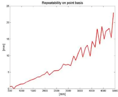
In the first step, the standard deviation was computed on a point basis for each distance. The repeatability results, shown in Figure 4, clearly indicate a near linear dependency on the range. The overall performance for the whole range is lower than 0.5%, which is quite excellent compared to earlier Flash LiDAR results (Kahlmann et al., 2006).
Figure 4. Repeatability result.
Figure 5 shows 2D error surfaces at two ranges, 1 m and 2.3 m, respectively. While the overall residual error numbers are small, their spatial distribution is somewhat unusual. Note that the circular pattern is caused by the distance calculation method, as described in (Khoshelham, 2011).
(a) (b)
Figure 5. Distribution of fitting errors at ranges (a) 1 m and (b) 2.3 m.
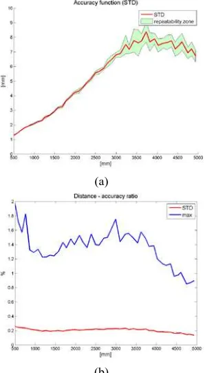
Based on the six measurement sets, the fitting plane residual errors were calculated and basic statistical parameters were determined, including maxima and STD for each range. Figure 5 shows the results, including a maximum error envelope and the STD (6a) as well as normalized values (6b). The results clearly indicate good accuracy performance, as at the shortest Laser emitter
Laser sensor (3D camera) RGB sensor (2D
object distance, the STD is lower than 1 mm and the maximum error is 1 cm, while at 3.5 m (the ambiguity limit) the STD is 7 mm and the maximum is 5 cm. Theoretically, the STD function should be of quadratic form based on the used calculation method, yet the curve looks almost linear. Normalized for the range, the STD is about 0.2% of distance while the maximum error is about 1.6%, as shown in Figure 6b. More details of this test are explained in (Toth et al., 2012).
(a)
(b)
Figure 6. STD of residual surface fitting errors (a), and normalized statistical parameters (b).
3.2 Sphere Fitting Test
Based on the good experiences with plane fitting, a second test was performed. Instead of plane fitting, two spheres with a radius of 30 cm were measured. The test range was from 0.7 to 4 m with a step of 10 cm and each measurement was repeated 10 times. This type of measurement yields a better relative accuracy characterization and additional information can be collected about the effect of incidence angle. The spheres were directly connected to each other (Figure 7).
Figure 7. Filtered depth image
Figure 8. Fitted spheres (red points with residuals over 5 mm).
During the sphere fitting, the radius, center point and the fitting residuals were calculated. Obviously, the estimated radius should be comparable with the directly measured one, and similarly, the center point distances are also computable and should be twice the radius (Figure 9).
(a)
(b)
Figure 9. Radius of fitted spheres (a), and sum of radiuses and center point distances (b).
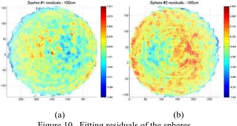
If a camera calibration (Khoshelham, 2011) is performed for both cameras (depth and RGB), the accuracy can be increased. Figure 9 shows an interesting result: the further objects the more down scaled. A scaling factor can be determined based on the object distance. The device internal calibration data should be extended with precise camera calibration and a scaling factor as function of distance should be introduced. The center point distance lacks this scaling error and shows somewhat better results. Figure 10 shows that the incidence angle has no or little International Archives of the Photogrammetry, Remote Sensing and Spatial Information Sciences, Volume XXXIX-B3, 2012
effect for this device, howeve,r some interesting symmetric error exists on the two spheres.
(a) (b)
Figure 10. Fitting residuals of the spheres.
The residuals (Figure 11) show comparable results to the plane fitting test. It is nearly linear and about 0.1 to 0.5% of the measurement distance. Based on this test, we may conclude that Kinect has really good accuracy in from 0.7 to 2 m, and over that range the standard deviations are noisier and seem to be stochastic. The fitted point number per sphere is in range 45K to 1.4K
Figure 11. Fitting residuals.
In the case of feature detection and adjustment, the relative accuracy has a large impact (Calignano et al., 2010). The location variation of sphere centers describes this feature detection accuracy reasonably well. Figure 12 shows that the points’ standard deviation in the repeatability test is mostly under 1 cm.
Figure 12. STD of center point location variation.
4. HUMAN MORPHOLOGIC MEASUREMENTS
Typical measurement range of human morphologic is exactly the same as that of the Kinect. In addition, mostly only certain parts of the human body are examined, i.e., the face. This means the range up to 2 m is acceptable. Facial reconstruction is a fast-growing business and requires accurate human morphologic measurements. In addition, it is very essential to have a prior face model in case of plastic surgery, for example, after an accident. For this purpose, the Kinect gives a very good solution since it’s widely available and inexpensive. The opportunity of high speed data acquisition (30fps) is also a benefit of this device, as it helps avoid errors on fast changing (mimics) and moving human body. The accuracy is the only limitation of this device, though it can be increased by camera calibration (including special scaling factor) and using of multiple devices. The post processing and model generation should be done in a special way (Figure 13); some points can be dropped and key points should be used with higher weight (Varga et al., 2008).
Figure 13. Key points (red) locations on a human face (Varga et al., 2008).
5. CONCLUSION
In our experiences, the Kinect sensor has shown good and consistent performance. The tests confirmed that rather good quality 3D imagery can be acquired in close range by this absolutely inexpensive sensor. The availability of several open source tools and the existence of an active user community make the integration of the Kinect sensor fairly simple, including basic data processing tasks too. While the Kinect is not a typical mapping sensor, its performance level makes it feasible to several applications, like human morphologic measurements.
6. ACKNOWLEDGEMENTS
The research work is funded by Hungarian Scientific Research Fund (OTKA no. 73251)
REFERENCES
Aoki, Y., Hashimoto, S., Terajima, M., Nakasima, A., 2000. Simulation of postoperative 3d facial morphology using a physic-based head model. International Archives of Photogrammetry and Remote Sensing. Vol. XXXIII, Supplement B5. Amsterdam, Holland, pp. 12-19.
Calignano, F., Moos, S., Vezzetti, E., 2010. Analysing the facial morphology with a three-dimensional geometrical features approach. ISPRS TC VII Symposium – 100 Years ISPRS, Vienna, Austria, July 5–7, 2010, IAPRS, Vol. XXXVIII, Part 7B, pp. 618-621.
Github, https://github.com/avin2/SensorKinect (10 Apr. 2012)
Kahlmann, T., Remondino, F., Ingensand, H., 2006. Calibration for increased accuracy of the range imaging camera SwissRanger, ISPRS Commission V Symposium 'Image Engineering and Vision Metrology', Dresden, Germany, pp. 136-141.
Khoshelham, K., 2011. Accuracy Analysis of Kinect Depth Data. ISPRS Journal of Photogrammetry and Remote Sensing, Vol. XXXVIII-5/W12, p. 6.
Konolige, K., Mihelich, P., 2010. Technical description of Kinect calibration. http://www.ros.org/wiki/ kinect_calibration/technical (10 Apr. 2012)
Microsoft, 2010. Kinect. http://www.xbox.com/en-us/kinect/ (10 Apr. 2012)
OpenNI, http://openni.org/Documentation/ProgrammerGuide .html (10 Apr. 2012)
PMD, http://www.pmdtec.com/fileadmin/pmdtec/downloads/ documentation/datasheet_camcube.pdf (10 Apr. 2012).
PrimeSense, http://www.primesense.com (10 Apr. 2012)
Schrott, P., Szabo, Gy., Fekete, K., 2008. Data Acquisition Possibilities for face Reconstruction Purpose. The International Archives of the Photogrammetry, Remote Sensing and Spatial Information Sciences. Beijing, China, Vol. XXXVII, Part B5, pp. 817-822.
Shan, J., Toth, C.-K., 2008. Topographic Laser Ranging and Scanning: Principles and Processing. Boca Raton, FL: Taylor & Francis.
Toth,K. C., Molnar, B., Zaydak, A., Grejner-Brzezinska, A. D, 2012. Calibrating the MS Kinect Sensor, ASPRS 2012 Annual Conference. Sacramento, USA
Varga, E., Hegedűs, I., Földváry, L., 2008. Optimalization of density and distribution of stereophotograph measurement points for a face. Proceedings of the Third Hungarian Conference on Biomechanics. Budapest, Hungary, pp. 387-393.
Vosselman, G., Maas, H.-G., 2010. Airborne and Terrestrial Laser Scanning. Whittles Publishing, Caithness, Scotland, UK. International Archives of the Photogrammetry, Remote Sensing and Spatial Information Sciences, Volume XXXIX-B3, 2012