SENSORS FOR LOCATION-BASED AUGMENTED REALITY
THE EXAMPLE OF GALILEO AND EGNOS
Alain Pagania∗, Jos´e Henriquesa, Didier. Strickera b a
German Research Center for Artificial Intelligence (DFKI) bTechnical University Kaiserslautern
Commission I, WG I/5
KEY WORDS:Augmented Reality, Sensors, Galileo, Photogrammetry
ABSTRACT:
Augmented Reality has long been approached from the point of view of Computer Vision and Image Analysis only. However, much more sensors can be used, in particular for location-based Augmented Reality scenarios. This paper reviews the various sensors that can be used for location-based Augmented Reality. It then presents and discusses several examples of the usage of Galileo and EGNOS in conjonction with Augmented Reality.
1. INTRODUCTION
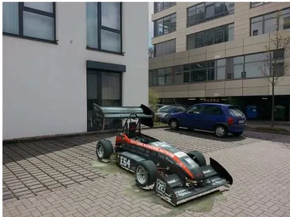
The concept ofAugmented Reality(AR) has seen a fast-growing gain of interest in the last few years. Two decades ago, AR emerged as a specific field at the frontiers of virtual reality and computer vision. From this start, this topic continually expanded, benefiting from advances in various fields — computer vision, human-computer interaction or computer graphics to cite a few — and from constant technological innovation, making the nec-essary hardware both small and cheap. Today, AR seems to ap-proach maturity, as simple AR-applications are commonly found in smartphones and are increasingly used for marketing opera-tions. The termAugmented Realityis recognized as a meaningful concept for a large, non-professional public. Early theoretical research on AR attempted to provide a definition of Augmented Reality according to the then available state-of-the-art and future expectations. The concept ofVirtuality Continuumwas described as early as 1994 by Milgram and Kishino (Milgram and Kishino, 1994), and is still used today for describing modern AR appli-cations. In 1997, Ronald Azuma defined AR as “a system that (1) combines real and virtual, (2) is interactive in real time and (3) is registered in 3D” (Azuma et al., 1997). Indeed, AR can be defined as a technology that supplements the real world with virtual (computer-generated) objects that appear to coexist in the same space as the real world. Figure 1 shows an example of Augmented Reality for small workspaces: here the virtual car is placed on top of a real book.
To achieve the necessary 3D registration, some sort of sensor is necessary. Because the aim of AR is often toaugment an ex-isting image, the sensor of choice is in many cases the camera that produced the image. Here the image itself is used as in-put data for comin-puting the parameters to enable AR. However, other sensors can be used instead of – or in addition to – the camera for producing better results. In this paper, we review the various sensors that can be used for AR, starting from im-age analysis up to positioning using Global Navigation Satellite Systems (GNSS). We show that this last example is particularly well-suited for location-based AR scenarios.
The remainder of this paper is organized as follows: after a short description of the main tasks of Augmented Reality, we present a
∗Corresponding author
Figure 1: Example of AR application. Virtual car on a real parking lot
survey of sensors and related methods used for AR. We then take the example of Galileo and EGNOS to show of GNSS informa-tion can help in locainforma-tion-based Augmented Reality.
2. AUGMENTED REALITY COMPONENTS
In AR, the main task is to extend the user’s senses (and in partic-ular its vision) in order to present him/her additional information in form of virtual objects. Therefore, one important component in AR is arendering enginecapable of rendering virtual objects on top of an existing background image. For a realistic integra-tion, care has to be taken to correclty model light sources, and to consider possible occlusions or shadows from the real objects onto the virtual ones. A study of the rendering component in AR is out of scope of this paper.
must be known or computed from the image. In addition, some prior information about the underlying scene has to be known and modelled in order to correctly position the virtual objects. For example, the position of the ground plane has to be defined to serve as support for placing the virtual objects. Most if not all of the necessary information can be recovered by analysing the image content in a three-dimensional computer vision approach (Faugeras, 1993). The camera internal parameters – also called
intrinsic parameters– can usually be computed once for all in a
calibration procedure.
This procedure usually involves the acquisition of images of a calibration pattern. With sufficient images, it is possible to re-trieve information such asfocal distance,position of the principal point, ansskew factor. When assuming a non-zooming camera without automatic re-focus, these parameters can be considered constant so that the calibration procedure has to be done only once.
The problem of finding the camera position and oriention – also known aspose estimation problem– consists in finding the extrin-sic parameters, i. e. the camera rotation and translation relative to a fixed coordinate system. In many applications, a real-time pose etimation technique is desirable. Here again, analysis of the image properties and of the underlying scene geometry can lead to very precise and fast results. This is particularly true when the geometry can by reconstructed beforehand using multiple im-ages (Hartley and Zisserman, 2000), but it has also been shown that even a single image contains in some cases sufficient infor-mation for computing the pose through known objects, points of lines (Criminisi et al., 2000). When considering a complete video sequence, this pose estimation has to be repeated for each novel image. In that case, it can be useful to use the last known pose as initial guess for computing the pose of the camera for a novel image. This is the reason why pose estimation can be seen as tracking problem that can be solved using Bayesian filtering ap-proaches (Thrun et al., 2005).
3. SENSORS FOR POSE ESTIMATION
The pose estimation problem – sometimes called tracking prob-lem – amounts to track the viewer’s movement with six degrees of freedom(6DOF): three variables (x, y, and z) for position and three angles (yaw, pitch, and roll) for orientation. In many cases, a model of the real objects in the scene must be known in ad-vance, but it does not need to be an accurate 3D model of the scene.
3.1 Inside-out and outside-in pose estimation
Generally the pose estimation methods can be split in two classe: the inside-out tracking methods and the outside-in tracking meth-ods. Inoutside-in pose estimation, the user position is observed by an external sensor. In an optical context, this is done usu-ally by adding some sort of markers to the head-worn device, and using a camera as external sensor. It can also use diverse other positioning methods. One major problem of outside-in tracking is that the range of movements of the user is limited to the field of view of the external camera. If the user moves outside of this field, or if the head rotation is too large, the tracking will break.
Ininside-out pose estimation, the sensor is placed on (or near
to) the user and its pose is computed from the observations. Usu-ally, one or more cameras are used, which are positioned so as to have an observation angle very close to the users eyes. Inside-out tracking has several advantages compared to Inside-outside-in: first, the range of movements is not limited by the field of view of an
Figure 2:Outside-in vs Inside-out tracking approaches
external sensor, but merely by the ability to recognize the sur-rounding. Second, when using a camera for pose estimation in an inside-out configuration, the pose is computed from image mea-surements and can be optimized for small reprojection errors in the image plane. This means that the computed pose is optimal for a seamless integration of virtual objects in the real surround-ing (i.e. the typical AR scenario). Third, when ussurround-ing an IMU, inside-out tracking allows for fusion of visual and inertial in-formation in a very efficient and mathematically sound manner (Bleser and Stricker, 2008).
3.2 Camera-based pose estimation
Because the aim of AR is to augment an image, the camera has been traditionally used as primary sensor for pose estimation in AR. The camera is usually used in an inside-out tracking ap-proach. By using one or several cameras, model-based approaches can recognise specific objects given an known model, or compute the relative movement between two images up to a scale factor. In order to create useful augmentations, for example for annotating a building with emergency exits, main stairways etc., a model of the scene or object to track has to be known in advance. This can also be useful to handle occlusions. When the scene can be pre-pared using non-natural objects, specific markers can be used in the so-calledmarker-based pose estimationmethod. If the prepa-ration is not possible and only objects naturally present in the scene can be used, the technique is calledmarkerlesspose esti-mation.
Figure 3:Example of a circular marker with augmentation
Marker-based pose estimationHistorically, the first way of
can be easier in the detection phase while providing a pose esti-mate that is more robust to noise (Koehler et al., 2011). Figure 3 shows an example of circular markers used in AR (Pagani et al., 2011).
Markerless pose estimationIn some situations, standard
mark-ers cannot be used directly. This happens for example when the environment should look natural to the user in applications like augmented advertisement in magazines or outdoor scenarios. In this case, the objects naturally present in the scene can be mod-elled in 3D and be used as known objects for pose estimation. The general condition is that the objects have sufficient texture to allow for a precise detection of keypoints on their surface. Once 2D points with known 3D coordinates have been detected in the scene, the pose of the camera is computed by solving the Perspec-tive from n Points (PnP) problem (Hartley and Zisserman, 2000). Because these methods rely on point matching techniques, the input data is rarely exempt of outliers. For this reason, robust techniques such as RANSAC (Fishler and Bolles, 1981) can be used in the pose estimation process.
3.3 Other sensors for pose estimation
Even if a digital camera is often used for Augmented Reality, the use of an imaging device is not absolutely necessary. In anoptical see-throughsetup, for example, no digital image is augmented, but rather the user’s vision directly. This is made possible by us-ing a see-through display, where only the virtual objects are ren-dered on a semi-transparent display, the background image being the real environment directly observed by the user. While see-through displays offer a better immersion and increase the notion ofpresence(Schuemie et al., 2001), they come with a number of new challenges such as the necessity to calibration the eye of the user (position and intrinsic parameters) (Tuceryan and Navab, 2000), and an increase importance of tracking position and low latency between the head movements and the tracker’s response.
Thus, besides the camera, several other sensors can be used for pose estimation, either alone or in addition to a camera in a hybrid approach.
3.3.1 Early trackers The first experiments of AR by
Suther-land (Tamura, 2002) were done with an HMD that was tracked mechanically through ceiling-mounted hardware. Later on, Raab et al. introduced the Polhemus magnetic tracker, which was able to measure distances within electromagnetic fields (Raab et al., 1979). While this type of tracker had much impact on AR re-search, its use is made difficult in environment containing metal-lic parts or magnetic fields.
3.3.2 Inertial Measurements Units IMUs are small devices
that contain accelerometers and gyroscopes. They usually de-liver acceleration in translation and rotation at high frequency (100 fps), and can be used in hybrid systems in a fusion approach (Bleser and Stricker, 2008). The main problem of IMUs is the er-rors due to drift. In order to avoid these erer-rors, the estimates must periodically be updated with accurate measurements. Nowadays, IMUs are commonly found in smartphones, although often not synchronized with the camera (Kim and Dey, 2009).
3.3.3 Radio-based trackers Radio frequency can be used for
example with RFID chips that can be positioned in the environ-ment to allow positioning (Willers, 2006). Compleenviron-mentary to RFID one can The wide-area IEEE 802.11b/g standards mainly used for wireless networking can also be used for tracking. The quality of the tracking highly depends on the number of chips of access points reachable in the environment (Bahl and Padmanab-han, 2000) (Castro et al., 2001).
3.3.4 Global Navigation Satellite Systems Global
Naviga-tion Satellite Systems (GNSS) are currently available or being implemented in many regions: The American Global Positioning System (GPS) (Getting, 1993), the Russian counterpart constel-lation Glonass, and the 30-satellite GPS Galileo, currently be-ing launched by the European Union. GNSS has an accuracy of about 10-15 meters, which would not be sufficient for precise position tracking, but several techniques to increase the preci-sion are already available. These techniques are referred to as
GNSS augmentation. GNSS augmentation is a method of im-proving the navigation system’s attributes, such as accuracy, re-liability and availability, through the integration of external in-formation into the calculation process. One can distinguish be-tween satellite-based augmentation systems (SBAS), that uses additional satellite-broadcast messages, and ground-based aug-mentation systems (GBAS), where the prevision is increased by the use of terrestrial radio messages. An example of SBAS is the European Geostationary Navigation Overly Service (EGNOS), that supplements the GPS, GLONASS and Galileo systems by reporting on the reliability and accuracy of the positioning data. This reduces the horizontal position accuracy to the metre level. A similar system used in North America is the Wide Area Aug-mentation System (WAAS) that provides an accuracy of about 3-4 meters. For more accuracy, the environments have to be prepared with a local base station that sends a differential error-correction signal to the roaming unit: differential GPS yields 1-3 meter accuracy, while the real-time-kinematic or RTK GPS, based on carrier-phase ambiguity resolution, can estimate posi-tions accurately to within centimeters (Van Krevelen and Poel-man, 2010).
3.3.5 Hybrid trackers When several sensors can be used in
the same setup, a hybrid method can be chosen. There are dif-ferent ways to use multiple sensors. The most simple one is to use the available sensors sequentially, where the interpretation of one sensor’s data depends on the measured data from the previous ones by using some heuristic. Another one is to fuse all available data using a Bayesian filter (Thrun et al., 2005), where the state is the pose to be estimated. For simple trackers, a Kalman filter can be used, but the complexity and in particular the non-linearity of the transition equations in the pose estimation problem often necessitates more elaborated models. For example, when dealing with multiple hypotheses, a particle filter can be useful.
4. GALILEO AND EGNOS FOR OUTDOOR AUGMENTED REALITY
In this section we present two possible uses of Galileo and EG-NOS as sensors for location-based augmented reality through two scenarios: a city tourist guide and utility network augmentation.
4.1 Example 1: City tourist guide
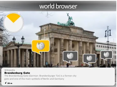
world browser
Wikipedia
The Brandenburg Gate (German: Brandenburger Tor) is a former city gate and one of the main symbols of Berlin and Germany
Figure 4:AR Labeling for world browsing. Exemplary appli-cation in the style of the Wikitude world browser
that case, the accuracy of standard GNSS such as Galileo (around 10m) could be sufficient for defining the coarse location).
A good application example is an AR-city guide using a smart-phone. In that case, the user’s coarse position (for example at the level of a street) can be obtained by Galileo positioning. If the smartphone contains a compass, the horizontal orientation of the device can also be obtained. Thus is it possible to know ap-proximately where the user is and where he/she is looking at. With this simple approach, the system can already provide in-formation such as the name of distant buildings or the direction and distance of other cities. This type of coarse pose estimation was commonly used in early smartphone AR applications such as Wikitude (Madden, 2011) and contributed to the success of AR for early adopters. Figure 4 shows an example of such a world browser application.
Another advantage of knowing the coarse position of the user is that further models that are required for a more precise pose esti-mation can be downloadedon demand, depending on the location of the user. For example, when the system detects that the user is in the front of a building, annotated pictures of this building can be downloaded and serve for a pixel-precise registration of live images with these pictures. It is this possible to deploy an AR application in an extremely large environment without shipping large models to all the users.
4.2 Example 2: Utility network augmentation
In other cases, the visual information might be difficult to model due to changing environments. For example, the European H2020 project LARA1aims at developing a new mobile device for help-ing employees of utilities companies in their work on the field. The device to be developed called the LARA System consists of a tactile tablet and a set of sensors that can geolocalise the device using the European GALILEO system and EGNOS capabilities. The system itself is a mobile device for utility field workers. In practice, this device will guide the field workers in underground utilities to see what is happening underworld. The system is us-ing Augmented Reality interfaces to render the complex 3D mod-els of the underground utilities infrastructure such as water, gas, electricity, etc. in an approach that is easily understandable and useful during field work. The 3D information is acquired from existing 3D GIS geodatabases.
Due to the fact that the device is intended to be used in building sites, the models that are usually required for vision-based pose estimation are difficult to establish and maintain. In this case,
1http://lara-project.eu
Figure 5: AR for utilities networks. Usage concept for the LARA system
it is therefore desirable to not rely on the camera as sensor for positional tracking.
Because the precision of about 10 meters is not sufficient, the use of a GNSS alone is not recommended for precise AR such as the one defined in the LARA scenario. Therefore the project makes use of the EGNOS system and other augmentations such as dif-ferential GPS (precision of less than 1 meter) and Precise Point Positioning (PPP) or Real Time Kinematics (RTK), with a pre-cision of about 1 cm. However, the obtained prepre-cision depends on the quality of the signal, the number of satellites currently ob-served and other factors. Therefore in this approach we estimate the obtained precision first using the EGNOS signal, and apply a heuristic to decide if we use directly the pose from the GNSS, or if we need to fuse this pose with visual information such as known points, or vanishing lines. All in all this system provides an accurate pose from GNSS when it is available and computes a better pose estimate with visual hints when the accuracy of the GNSS pose is not enough for AR. Figure 5 shows the usage con-cept for the LARA system.
5. CONCLUSION
In this paper, we reviewed different sensors that can be used for pose estimation in Augmented Reality. Even if the camera is the sensor of choice in most of the cases, we have seen that the use of Global Navigation Satellite Systems Information such as Galileo and EGNOS is convenient for location-based services, especially in outdoor scenarios. We provided two examples of use, the first one using coarse localization from GNSS to provide the metadata necessary for visual tracking, the second one relying on precision estimaton for defining the hybridation strategy to use.
ACKNOWLEDGEMENTS
The work leading to this publication has been partially funded by the European GNSS Agency through the Horizon 2020 project LARA, under grant agreement No GA 641460.
REFERENCES
Azuma, R. et al., 1997. A survey of augmented reality. Presence: Teleoperators & Virtual Environments 6(4), pp. 355–385.
Bleser, G. and Stricker, D., 2008. Advanced tracking through ef-ficient image processing and visual-inertial sensor fusion. Com-puter & Graphics.
Castro, P., Chiu, P., Kremenek, T. and Muntz, R., 2001. A prob-abilistic room location service for wireless networked environ-ments. In: Ubicomp 2001: Ubiquitous Computing, Springer, pp. 18–34.
Criminisi, A., Reid, I. and Zisserman, A., 2000. Single view metrology. International Journal of Computer Vision 40(2), pp. 123–148.
Faugeras, O. D., 1993. Three-Dimensional Computer Vision: a Geometric Viewpoint. MIT Press.
Fishler, M. A. and Bolles, R. C., 1981. Random sample con-sensus: A paradigm for model fitting with applications to im-age analysis and automated cartography. Communications of the ACM 24(6), pp. 381–395.
Getting, I. A., 1993. Perspective/navigation-the global position-ing system. Spectrum, IEEE 30(12), pp. 36–38.
Hartley, R. and Zisserman, A., 2000. Multiple View Geometry. Cambridge University Press.
Kim, S. and Dey, A. K., 2009. Simulated augmented reality wind-shield display as a cognitive mapping aid for elder driver navi-gation. In: Proceedings of the SIGCHI Conference on Human Factors in Computing Systems, ACM, pp. 133–142.
Koehler, J., Pagani, A. and Stricker, D., 2011. Detection and identification techniques for markers used in computer vision. In: Visualization of Large and Unstructured Data Sets - Applications in Geospatial Planning, Modeling and Engineering (IRTG 1131 Workshop), pp. 36–44.
Madden, L., 2011. Professional augmented reality browsers for smartphones: programming for junaio, layar and wikitude. John Wiley & Sons.
Milgram, P. and Kishino, F., 1994. A taxonomy of mixed reality visual displays. IEICE Transactions on Information and Systems 77, pp. 1321–1329.
Pagani, A., Gava, C., Cui, Y., Krolla, B., Hengen, J.-M. and Stricker, D., 2011. Dense 3d point cloud generation from multiple high-resolution spherical images. In: Proceedings of the Interna-tional Symposium on Virtual Reality, Archaeology and Cultural Heritage (VAST).
Project, n.d. Lara. http://lara-project.eu/.
Raab, F. H., Blood, E. B., Steiner, T. O. and Jones, H. R., 1979. Magnetic position and orientation tracking system. Aerospace and Electronic Systems, IEEE Transactions on (5), pp. 709–718.
Schuemie, M. J., Van Der Straaten, P., Krijn, M. and Van Der Mast, C. A., 2001. Research on presence in virtual reality: A survey. CyberPsychology & Behavior 4(2), pp. 183–201.
Tamura, H., 2002. Steady steps and giant leap toward practical mixed reality systems and applications. In: VAR’02.
Thrun, S., Burgard, W. and Fox, D., 2005. Probabilistic Robotics (Intelligent Robotics and Autonomous Agents). The MIT Press.
Tuceryan, M. and Navab, N., 2000. Single point active alignment method (spaam) for optical see-through hmd calibration for ar. In: Proceedings of the IEEE and ACM International Symposium on Augmented Reality (ISAR).
Van Krevelen, D. and Poelman, R., 2010. A survey of augmented reality technologies, applications and limitations. International Journal of Virtual Reality 9(2), pp. 1.
Wagner, D. and Schmalstieg, D., 2007. Artoolkitplus for pose tracking on mobile devices. In: Proceedingsofthe Computer Vi-sion Winter Workshop (CVWW).