An investigation of the stress singularity near the free edge of scarf joints
Z.Q. Qian, A.R. Akisanya *
Engineering Department, University of Aberdeen, King’s College, Aberdeen AB24 3UE, U.K.
(Received 1 October 1997; revised and accepted 10 August 1998)
Abstract – The singular stress field which develops at the interface corner of a scarf joint between two bonded elastic solids is investigated. Depending upon the scarf angle and the material elastic properties, the singular stresses at a radial distancerfrom an interface corner may be expressed in the formH rλ−1, whereλ−1 is the order of the stress singularity andH is the intensity of the singularity. The intensityH of the singularity at the interface corner of scarf joints subjected to a remote uniform tension is evaluated for various material combinations and a range of scarf angles using a combination of the finite element method and a path independent contour integral. Two types of scarf joints are considered: (i) a scarf joint between two long bi-material strips and (ii) a scarf joint consisting of a thin elastic layer sandwiched between two substrates. The role of the intensityH, which determines the amplitude of the stress field within the singularity zone, is examined and the implications of the results for the initiation of joint failure are discussed.Elsevier, Paris
stress singularity / bonded joints / contour integral / failure initiation / finite element method
1. Introduction
Bonded joints containing two or more layers of dissimilar materials are increasingly used for various engineering and structural applications. For example, they are used in the production of electronic, automobile and aerospace components. The failure of these joints and of many other multi-layer systems often initiates at the interface corner, where the interface of the joint intersects the traction-free surfaces. It is therefore important to characterise the stress and/or strain field near the interface corner so that this type of failure can be accurately predicted and minimised.
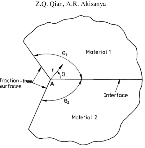
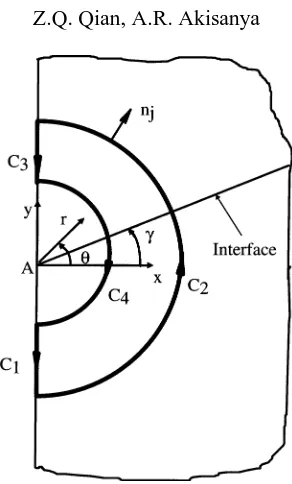
In general, the geometrical configuration at the free edge of two bonded dissimilar materials is characterised by the angles θ1 and θ2 which the interface makes with the traction-free surfaces at the interface corner, as shown for example in figure 1; the interface corner is denoted byAin figure 1. The two materials in figure 1 are assumed to be elastic and are perfectly bonded along the interface. A stress singularity may develop at the interface corner under an applied loading. Depending on the material elastic properties and on the edge geometry (i.e.θ1andθ2) the stress singularity may be of the formH rλ−1. Here,ris the radial distance from the interface cornerA, H is the intensity of the singularity andλ−1 is the order of the stress singularity. We shall refer to this as theH-field, in contrast with a crack tip K-field (Akisanya and Fleck, 1997; Akisanya, 1997). TheH-field dominates only a local region near the interface corner of the joint and as such it is sometimes referred to as a free-edge effect. The intensityH of the free-edge singularity will hereafter be referred to as the
free-edge intensity factor.
The value ofλ(and the corresponding value of the intensity H) may be real or complex, depending upon the relative elastic properties of the materials and upon the edge geometry. The magnitude of the intensityH
Figure 1. General configuration at the free-edge of two bonded dissimilar materials.
of the singularity, which characterises the amplitude of the stress state near the interface corner, depends upon the edge geometry, the material elastic properties and upon the remote loading. In this paper, we focus on scarf joints for which the material elastic properties and the scarf angle are such that the values of bothλandH are real.
The evaluation ofλ for various edge geometries has been discussed extensively in the literature (see, for example (Williams, 1952; Bogy, 1971; Hein and Erdogan, 1971; Kelly et al., 1992)). However, the evaluation of the intensity of the singularity,H, has received little attention. The significance ofH in the design of joints is two-fold. Firstly, a detailed characterisation of the singular field at an interface corner (or a free edge) requires a knowledge of the magnitude of bothH and λ for various industrially used joint geometries. Secondly, the magnitude ofH can be used to predict the initiation of failure at the interface corner in a manner similar to the use of conventional crack tip stress intensity factor for predicting the onset of crack growth (Gradin, 1982; Groth and Brottare, 1988; Hattori et al., 1989). Failure at the interface corner occurs when the magnitude ofH
reaches a critical value, sayHc, which will have to be determined by carefully designed experiments. Therefore, a detailed calibration of the intensity of the free-edge singularityH for various specimen geometries, material combinations and loading conditions is required for the effective application of a H-based failure initiation criterion.
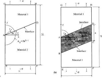
Figure 2. Scarf joint geometries subjected to a uniform remote tensionσ. (a) A scarf joint consisting of two long elastic materials. (b) A scarf joint consisting of a thin layer of elastic solid sandwiched between two substrates.
Akisanya and Fleck (1997) and Akisanya (1997) have recently evaluated the magnitude of H via a combination of the finite element method and a path independent contour integral for: (i) a butt joint between two long strips of materials and (ii) a butt joint consisting of a thin elastic layer sandwiched between two elastic and isotropic solids. The advantage of this method over the extrapolation method is that the magnitude ofH
can be determined by using the stress and displacement fields away from the interface corner, and hence the accuracy does not depend critically on the mesh density close to the free edge.
In this paper, the singular stress field which develops at the interface corner of a scarf joint between two dissimilar materials is examined. Two joint configurations are considered: (i) a scarf joint between two long strips of elastic materials (figure 2a), and (ii) a scarf joint consisting of a thin layer of elastic solid sandwiched between two identical substrates (figure 2b). Both joints are subjected to a uniform remote tensionσ and the intensityH of the singularity at one of the interface corners is evaluated for a wide range of material properties and various scarf angles, using a combination of the finite element method and a path independent contour integral. The role of the intensityH in controlling the stress field within the singularity zone is examined. The implications of the results for the failure of scarf joints are discussed.
2. Statement of problem
co-ordinates centred at the interface cornerA. The interfaceAD is inclined at a scarf angleγ to thex-axis. The material in the region γ < θ < π/2 is termed material 1 while the material in the region −π/2< θ < γ is referred to as material 2.
The other scarf joint geometry considered in this paper is shown in figure 2b. It consists of a thin layer of elastic solid (material 2) of thickness h sandwiched between two identical substrates (material 1). For consistency, the width of the joint is denoted by w and the total length by 2L; both L and w in figure 2b are assumed to be much greater than the layer thicknessh. The two interfaces between the thin elastic layer and the substrates intersect the traction-free surfaces at the interface corners A, B, C and D, as shown in
figure 2b. As for the scarf joint shown in figure 2a, rectangular Cartesian and plane polar coordinates (x, y)
and(r, θ )respectively, centered at the interface cornerAare used to describe the joint geometry and the stress distribution. The thin layer is inclined at a scarf angle γ to the x-axis as shown in figure 2b. For both scarf joints (i.e. figures 2a and 2b) the strips are subjected to a uniform remote tensionσ, and are assumed to be sufficiently thick for plane strain conditions to prevail. We further assume that the two materials are perfectly bonded along the interface.
The stress field within a local region around an interface corner, sayA, may be of the formH rλ−1, whereris
the radial distance from the corner andλ−1 is the order of the stress singularity. In this paper, the intensityH
of the singularity is evaluated for the scarf joints shown in figures 2a and 2b. The extent of the region dominated by the free edge singularity is estimated by comparing the finite element solutions with the singular asymptotic solutions.
The stress distribution in a body loaded by prescribed surface traction in plane strain or plane stress depends on only two combinations of the elastic constants. The two elastic mismatch parameters are defined for plane strain by Dundurs (1969) when material 2 is more compliant than material 1, and is negative when material 2 is stiffer than material 1.
α=β=0 when the elastic properties of both materials are identical, and switching materials 1 and 2 reverses the signs ofα andβ. It is well known that the values ofα and β for all physically admissible combinations of materials are contained within a parallelogram inα-β space. The corners of the parallelogram are located at the point (α, β)=(1,0), (−1,0), (1,0.5) and (−1,−0.5). Further, the (α, β) values for typical material combinations are concentrated alongβ=0 andβ=α/4 lines inα−β (Suga et al., 1988). Hence, we focus our discussion in the current paper on material combinations withβ=0 andβ=α/4.
3. The asymptotic singular solution
3.1. IntensityH of the free-edge singularity
By using a complex variable formulation, it is shown in the Appendix that the singular stress and displacement fields near the interface cornerA(see figure 2) are of the form
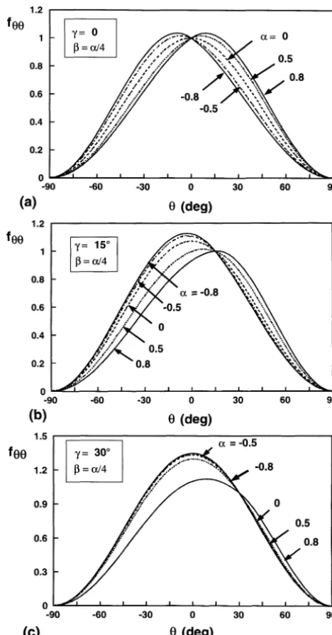
Figure 3. The non-dimensional functionfθ θ as a function ofθ, for various values of material elastic mismatch parametersαandβ (=α/4)and of scarf angleγ. (a)γ=0, (b)γ=15◦and (c)γ=30◦.
where(i, j )≡(r, θ ), m (=1,2) is the material index, µm denotes shear modulus, λ−1 is the order of the stress singularity and,fijmandgimare non-dimensional functions of material parameters(α, β), the scarf angle
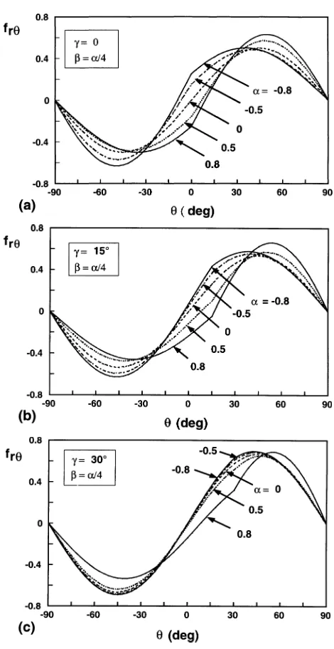
Figure 4. The non-dimensional functionfr θas a function ofθ, for various values of material elastic mismatch parametersαandβ (=α/4)and of scarf angleγ. (a)γ=0, (b)γ=15◦and (c)γ=30◦.
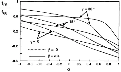
which is measured by the ratiofrθ/fθ θ, is shown in figure 5 as a function of the material parameterαand for a range of scarf angles. A general discussion on these functions is given in Section 4.
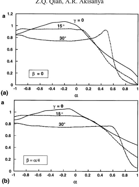
Figure 5. The ratio of shear to normal stressfr θ/fθ θat the interface as a function of material elastic mismatch parametersαandβ (=0 andα/4), for scarf anglesγ=0,15◦and 30◦.
Depending on the material elastic properties and on the scarf angle, the stress field at an interface corner of the joint geometries shown in figure 2 may take one of three forms, as discussed in the Appendix. In this paper we focus on the evaluation of the magnitude ofH for a free-edge singularity of formH rλ−1, where bothH
andλare real constants.His defined such that at a distancer from the interface corner and along the interface
(θ=γ ), the stress component normal to the interface,σθ θ, in the region dominated by the singularity is given by
σθ θ1 =σθ θ2 =H rλ−1 (alongθ=γ ), (3)
where the superscripts 1 and 2 denote the two materials. The magnitude ofH depends, in general, upon the free-edge geometry, elastic mismatch parameters and upon the remote loading. Dimensional considerations dictate thatH be related to the joint geometry and material elastic properties by Akisanya and Fleck (1997), Akisanya (1997), Reedy (1990, 1993).
H=σ l1−λa(α, β, γ ), (4)
whereσ is the magnitude of the applied uniform remote tension,l is a characteristic length scale and a is a dimensionless constant function of the scarf angleγ, and of the material elastic parameters(α, β). In the current study, we have chosenlas the smallest length scale in a particular joint geometry. Therefore,l≡wfor the scarf joint consisting of two long elastic strips of materials each of widthw(figure 2a), andl≡hfor the scarf joint consisting of a thin layer of elastic solid of thicknesshsandwiched between two substrates (figure 2b). We shall evaluateH, and hence the non-dimensional constant a,by a combination of the finite element method and a path independent contour integral.
3.2. Evaluation of the free-edge intensity factorH
Figure 6. A closed integration path around the interface cornerA.
Consider a closed contourC (=C1+C2+C3+C4)around the interface cornerA, as shown in figure 6. Betti’s reciprocal law can be stated as
I
C
σiju∗i −σ ∗ ijui
nj ds=0, (5)
where(i, j )≡(r, θ )represent plane polar co-ordinates centred at the interface corner (see figure 6), σij and
ui are the free-edge singular stress and displacement fields given by (2), σij∗, u ∗
i are auxiliary fields satisfying the same boundary conditions asσij andui, nj is the outward unit normal toC, and ds is an infinitesimal line segment ofC. By appropriate choice of the auxiliary field (σ∗
ij, u∗i)the integral (5) can be used to determine the free-edge intensity factorH.
In the evaluation of H the auxiliary fields σij∗ and u∗i are chosen as the free-edge singular stress and displacement fields given by (2) with intensity H∗ and λ replaced by λ∗= −λ. The starred fields (σ∗
ij, u∗i) withλ∗= −λsatisfy the same boundary conditions as those for the unstarred fields(σij, ui). These boundary conditions are as stated in Eq. (A.3) of the Appendix. The unstarred fields are obtained for both scarf joints using the finite element method. The value ofH∗ for the auxiliary field is chosen such that the evaluation of
(5) by the domain integration method gives the intensityH for the elastic state of interest. A more detailed description of the procedure for the evaluation ofH is given elsewhere (Akisanya and Fleck, 1997). Once the value ofH has been obtained, we calculate the non-dimensional constant a(α, β, γ )via (4).
Elastic analysis of the scarf joints shown in figure 2 has been carried out using the finite element code ABAQUS.1 The finite element mesh consists of 618 eight-node plane strain isoparametric, quadrilateral elements. For the scarf joint between two long isotropic solids shown in figure 2a the width of the strip w
is taken as unity andL=10w. Roller boundary conditions are applied along the bottom edge of material 2 (i.e. alongEF in figure 2a) while a uniform remote tensionσis applied along the top edge of material 1 (i.e.GH). In addition, pointF at the bottom edge is fixed in the finite element model to prevent rigid body movement. For
4. Results and discussion
One of the aims of a joint design engineer is to use joint geometries and/or material combinations which remove the stress singularity at the free edge (i.e. ensures that the stress field is of O(1)). In the design of a scarf joint between two given materials, the scarf angleγ may be selected such that the stress singularity is eliminated (i.e.λ>1). Alternatively, if the scarf angle is given, the material combinations (characterised by the material parametersαandβ) may be chosen such that the free-edge stress singularity vanishes. However, it is impossible to completely eliminate the singularity in many practical joint problems, but the effects of the singular field can be minimised by having a fundamental understanding of joint failure at the free edge. This requires a knowledge of the magnitude of the intensityH and the order of the stress singularityλ−1.
The stress components in the region dominated by the stress singularity and at a radial distance r from the interface corner are of the form given by (2). The singular stresses and the corresponding displacements depend on the magnitude ofH, λand on the non-dimensional functionsfij andgi; where(i, j )≡(r, θ ). In the following we discuss the results for the non-dimensional functions and for the intensityH.
4.1. Non-dimensional functionsfij
The non-dimensional functionsfij depend onλ, θ, γ and on the material elastic mismatch parameters(α, β) (see the Appendix). Typical results forfθ θ and frθ over the full range ofθ (−π/26θ 6π/2)are shown in
figures 3 and 4 respectively, for various values of the material parameters (α, β =α/4) and for scarf angles
γ =0, 15◦ and 30◦. Recall that the interface is along θ =γ and the material in the interval −π/2< θ < γ
is termed material 2 while the material occupying the regionγ < θ < π/2 is referred to as material 1. The material parameter α >0 if material 2 is more compliant than material 1 and α <0 if material 2 is stiffer than material 1. The functionfθ θ only reflects a qualitative distribution of the stress component σθ θ; the actual magnitude ofσθ θ depends, in addition, onH.
By definition (Eq. (3)) the function fθ θ =1 along the interface (θ =γ ), and the values offθ θ and frθ are consistent with the stress continuity conditions at the interface and the traction-free conditions atθ = −π/2 and at θ =π/2. When the scarf angle γ =0 (see figure 3a) and the elastic properties of the materials are identical (i.e.α =β=0), the maximum value offθ θ, and hence of the stress component σθ θ, occurs at the interface. However, when the elastic properties of the materials are different, the maximum value offθ θoccurs slightly away from the interface and in the stiffer material. For example, the maximum value offθ θ equals 1.02 atθ =6◦for(α, β)=(0.5,0.125), and equals 1.04 atθ=9◦when(α, β)=(0.8,0.2). These results indicate that for tensile butt joints(γ =0)between two dissimilar brittle materials, higher stresses are developed in the stiffer material and away from the interface.
The values offθ θ for scarf joints withγ =15◦andγ =30◦are shown in figures 3b and 3c, respectively. As forγ =0, the maximum values offθ θ occur away from the interface and in the stiffer material. For example, whenα=0.8, the maximum value offθ θ occurs atθ=17◦forγ =15◦(figure 3b), and atθ=10◦forγ =30◦ (figure 3c). The material parameterαhas a negligible effect on the magnitude of the functionfθ θ when material 1 is much more compliant than material 2 (i.eα <−0.5) and the scarf angle is large, for example,γ =30◦.
Table Ia. The non-dimensional constant a for a scarf joint between two long strips of materials as a function of the scarf angleγ, and material elastic parametersαandβ (=0).
α γ=0 γ=15◦ γ=30◦ γ=45◦ γ=60◦ γ=75◦
−0.99 0.3526 0.4524 0.5141 0.5 0.03017 0.0008
−0.8 0.4409 0.4920 0.5198 0.5 0.2878 0.0155
−0.5 0.6350 0.6025 0.5689 0.5 0.2815 0.0380
−0.2 0.8964 0.7709 0.6535 0.5 0.2638 0.0574 0.0 1.0 0.9326 0.7483 0.5 0.2508 0.0671 0.2 0.8973 1.0424 0.9273 0.5 0.2355 0.0729 0.5 0.6304 0.7249 1.5574 0.5 0.2128 0.0755 0.8 0.4402 0.3769 0.3076 0.5 0.1905 0.0689 0.99 0.3542 0.2422 0.1189 0.5 0.1825 0.0672
Table Ib. The non-dimensional constant a for a scarf joint between two long strips of materials as a function of the scarf angleγ, and material elastic parametersαandβ (=α/4).
α γ=0 γ=15◦ γ=30◦ γ=45◦ γ=60◦ γ=75◦
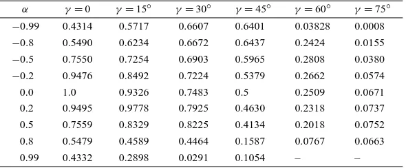
−0.99 0.4314 0.5717 0.6607 0.6401 0.03828 0.0008
−0.8 0.5490 0.6234 0.6672 0.6437 0.2424 0.0155
−0.5 0.7550 0.7254 0.6903 0.5965 0.2808 0.0380
−0.2 0.9476 0.8492 0.7224 0.5379 0.2662 0.0574 0.0 1.0 0.9326 0.7483 0.5 0.2509 0.0671 0.2 0.9495 0.9778 0.7925 0.4630 0.2318 0.0737 0.5 0.7559 0.8329 0.8225 0.4134 0.2018 0.0752 0.8 0.5479 0.4589 0.4464 0.1587 0.0767 0.0663 0.99 0.4332 0.2898 0.0291 0.1054 – –
i.e. continuity ofσrθ across the interface and traction-free conditions at surfacesθ= ±π/2. For all the material combinations and scarf angles shown in figure 4, the absolute maximum of frθ is located within the stiffer material.
Interfacial toughness data are usually presented in terms of the phase angles, which is a measure of the relative amount of the shear stress to the normal stress at the interface. Figure 5 shows the ratio frθ/fθ θ at the interface in the region dominated by the free-edge singularity for various material combinations and scarf anglesγ =0, 15◦and 30◦. The stress ratioσrθ/σθ θ(=frθ/fθ θ)along the interface is independent of the radial distance from the interface corner and is significantly influenced by the material mismatch parametersα and
β, and by the scarf angleγ. The magnitude of the ratioσrθ/σθ θ is greater forβ=α/4 than forβ=0 whenα is positive and it is smaller forβ=α/4 than forβ=0 whenαis negative. The magnitude of the ratiofrθ/fθ θ increases with increasing scarf angleγ. Since interfacial toughness increases with increasing magnitude of interfacial phase angles (Akisanya and Fleck, 1992), the results shown in figure 5 confirms that scarf joints are ‘stronger’ than butt joints(γ =0).
4.2. The magnitude of intensityH
The free-edge intensity factorH is related to the geometry, material elastic properties and remote loading as given by Eq. (4). The values of the non-dimensional constant a for the two scarf joint geometries shown in
−0.99 0.8540 0.9187 0.8408 0.8668 0.9205 0.8130
−0.8 0.9214 0.9400 0.7966 0.9311 0.9431 0.7794
−0.5 1.0199 0.9452 0.7551 1.0234 0.9432 0.7547
−0.2 1.0712 0.9477 0.7451 1.0493 0.9414 0.7442 0.0 1.0 0.9330 0.7500 1.0 0.9330 0.7500 0.2 0.7921 0.8266 0.7788 0.8873 0.8825 0.7558 0.5 0.5045 0.4048 0.9051 0.6972 0.6782 0.7635 0.8 0.3109 0.1632 0.0714 0.5302 0.3796 0.3130 0.99 0.1469 0.0102 0.0179 0.4449 0.2406 0.0587
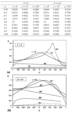
Figure 7. The non-dimensional constant a as a function of scarf angleγand material elastic mismatch parametersαandβ, for the scarf joint consisting of two long elastic strips. (a)β=0 and (b)β=α/4.
for the non-dimensional constant a are also plotted in figure 7 for the scarf joint between two long strips of material. In general, the magnitude of a at the interface cornerAof the scarf joint between two long strips of materials (figure 2a) is within the range 0<a61 whenλ <1 and a>1 whenλ>1; the free-edge stresses forλ>1 are non-singular. However, a<1 for large scarf angles(γ >45◦)irrespective of the value ofλ. We
Figure 8. The non-dimensional constant a as a function of scarf angleγ and material elastic mismatch parametersαandβ, for the sandwiched scarf joint. (a)β=0 and (b)β=α/4.
that whenλ <1, a increases with increasing β. The dependence of a on the scarf angle γ do not follow any consistent pattern except when the material parameterαis in the range −0.6< α <0 where a increases with decreasing magnitude ofγ.
The values of the non-dimensional constant a for the sandwiched scarf joint (figure 2b) are plotted in figure 8 forγ =0, 15◦ and 30◦. Whenγ =0, the values of a are identical to those obtained by Akisanya (1997). In
contrast to a butt joint(γ =0)between two long strips of materials, the magnitude of a for a sandwiched butt joint is not symmetric with respect toα=0. For a given magnitude of α, the value of a for a sandwiched butt joint(γ =0)is lower forα >0 than forα <0 (figure 8). Sinceλ(α, β, γ =0)=λ(−α,−β, γ=0)(see
figure A.1), the free-edge stresses in a butt joint are minimised when the more compliant material is used as the
sandwiched layer. For all the values ofγ considered, the magnitude of a decreases with increasing magnitude of the material parameterα; the rate of decrease is faster forα >0 than forα <0. The magnitude of a is lower forβ=0 than forβ=α/4 for all the cases except whenγ =0 and−0.4< α <0, where the magnitude of a is higher forβ=0 than forβ=α/4.
4.3. The extent of the singular stress field
The asymptotic singular stresses near the interface corner are calculated using Eq. (2) by making use of the numerically obtained values ofH andλ, and of the analytically derived expressions for the angular functions
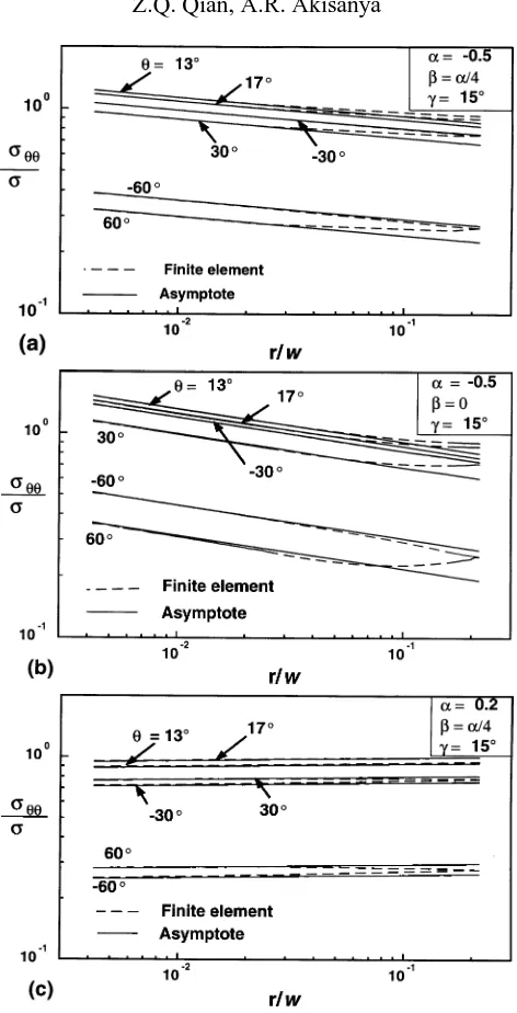
fij andgi. The extent of the region dominated by the free-edge singularity is estimated by comparing the finite element solutions with the asymptotic singular solutions. Typical results of the stress componentσθ θ near the interface corner along various radial directions are plotted against the distance from the interface corner in
figure 9, for the scarf joint geometry shown in figure 2a. The stress componentσθ θ has been normalised by the applied remote tensionσ, while the radial distancer, has been normalised by the width of the jointw.
Whenα= −0.5, β=α/4 andγ =15◦ (figure 9a), the asymptotic and finite element results forσ
θ θ are in good agreement in the stiffer material (i.e. material 2) and away from the interface, up to a radial distance
r =0.2w; the maximum difference between the two solutions is about 5% of the finite element solution. However, near the interface (i.e. alongθ =13◦ and θ =17◦) and also in material 1 (i.e. along θ =30◦ and
θ=60◦) the two solutions are only in agreement up to a radial distance r=0.04w. The comparison between the asymptotic and finite element solutions forσθ θ whenα= −0.5, β=0 andγ =15◦is shown in figure 9b; the effect of the material parameterβ on the extent of the singular field is negligible. The actual magnitude of
σθ θ depends, however, onβ. Figure 9c shows the comparison between the asymptotic solutions forσθ θ and the finite element solutions whenα=0.2 and β=α/4 with γ =15◦. Hereλ=1.01534, and the stresses at the interface corner are non-singular. The two solutions are in very good agreement along all directions and up to a radial distancer=0.2w and the stress componentσθ θ decreases as the interface corner is approached from within the materials. This is in contrast with other cases withλ <1 where the stresses increase as the interface corner is approached (see figures 9a and 9b).
The extent of the singular field for the scarf joint consisting of a thin layer of elastic solid sandwiched between two identical substrates is qualitatively similar to that shown in figure 9 for a scarf joint between two strips of materials; the singular filed dominates a large region near the interface corner relative to the layer thicknessh.
4.4. Fracture criterion for bonded joints
Equation (2) shows that the strength of the stress field near the interface corner is determined by the order of the stress singularity,λ−1, and the intensity,H;λdepends only on the elastic mismatch parameters,αandβ, and the scarf angle,γ. If the value ofλis identical for two different scarf joints, the free-edge intensity factor
H will have equal units and may be used for comparing their respective failure loads.
Figure 9. Comparison of the linear elastic finite element and asymptotic singular solutions for stress componentσθ θ. The stress componentσθ θ is normalised by the applied remote tensionσ, while the radial distancerfrom the interface corner is normalised by the joint widthw. (a)γ=15◦, α=
−0.5, β=α/4; (b)γ=15◦, α= −0.5, β=0; and (c)γ=15◦, α=0.2, β=α/4.
singularity magnifies the crack-tip stress intensity factors of an edge crack embedded within theH-field, and thus encourages the initiation and growth of cracks at the free edge (Akisanya and Fleck, 1997).
5. Concluding remarks
In this paper, we have investigated the stress state at the interface corner of scarf joints. The free-edge stresses can be written in the formH rλ−1f
free-edge singularity has been estimated by comparing the finite element solutions with the singular asymptotic solutions. The main conclusions are as follows:
• Free-edge stress singularity can be minimised by appropriate selection of materials and joint geometry, characterised by the scarf angle γ. These parameters should be chosen such that the magnitude of λis maximised and the intensity H is minimised.
• The free-edge singular field dominates a reasonably large region near the interface corner relative to the width of a scarf joint between two long strips of materials and, relative to the layer thickness of a scarf joint consisting of a thin layer of elastic materials sandwiched between two substrates. The extent of the free-edge singular field from the interface corner depends on the elastic mismatch parameters α and β, the scarf angleγ, and on the angular directionθ. If a tensile butt joint is to be made from a given pair of materials, the free-edge stresses are minimised when the more compliant material is sandwiched between the stiffer one.
• The intensity H can be used as a valid parameter for characterising the fracture strength of bonded structures, provided failure occurs within theH-dominance zone and the extent of the elastic singularity is greater than the size of any non-linear deformation. The critical value ofH at failure can be measured by experiments using the calibration given by Eq. (2). The units ofH, which are of the form (MPa) (mm)1−λ, do not allow a direct comparison of the magnitude of H between two different scarf joints unless both joints have the same magnitude ofλ.
Appendix
The eigen problem
In this appendix we derive the free-edge singular stress and displacement fields for the scarf joints shown in
figure 2. Consider a bi-material strip of widthwand length 2L (L≫w), subjected to a uniform remote tensile stressσ, as shown in figure 2. We assume that the two materials are perfectly bonded at the interface and that plane strain conditions apply. Let(x, y) and (r, θ )be rectangular and plane polar co-ordinates placed at the interface cornerA. The traction-free surfaces of both materials make an angle ofπ/2 with the x-axis, while the interface makes an angle ofγ with the x-axis, as shown in figures 2a and 2b. The material in the region
γ < θ < π/2 is classified as material 1 while the material occupying the region−π/2< θ < γ is referred to as material 2. The elastic properties of the two materials are characterised by Dundurs (1969) elastic mismatch parameters α and β as defined in (1). We describe below a procedure to determine the singular stress and displacement fields near the interface cornerA.
For the geometry shown in figure 2, the stresses and displacements in material m (m=1,2) around the interface corner in the absence of body forces can be expressed in terms of two complex potentials8mandm by Muskhelishvili (1953)
σθm−iσrθm=8′m(z)¯ +8′m(z)+ ¯z8′′m(z)¯ +z−1z¯ ′m(z),¯
σrm+iσrθm=8′m(z)¯ +8′m(z)− ¯z8′′m(z)¯ −z−1z¯ ′m(z),¯
umr +iumθ =(2µm)−1e−iθκm8m(z)−z8 ′
m(z)¯ −m(z)¯ .
Following Stern et al. (1976), Carpenter and Byers (1987) and England (1971), we assume the complex functions have the following asymptotic form asz→0,
81=Azλ; 1=Bzλ for material 1,
82=Czλ; 2=Dzλ for material 2, (A.2)
whereA (=A1+iA2), B (=B1+iB2), C (=C1+iC2)andD (=D1+iD2)are complex constants. We seek the free-edge stress and displacement fields that satisfy the following boundary conditions:
σ1
where superscripts 1 and 2 denote the material index. Substitution of (A.2) and (A.3) into (A.1) gives:
ei2γ (λ−1)A+λA¯+Be−i2γ −Cei2γ (λ−1)−λC−De−i2γ =0, (A.4)
By considering the real and imaginary parts of (A.4)–(A.7), we obtain eight homogeneous linear equations in the eight unknown coefficientsAj, Bj, Cj, Dj(j=1,2). A non-trivial solution to the equations exist only if the determinant of the coefficient matrix vanishes. This occurs when the eigen-valueλsatisfies the characteristic equation
The characteristic equation (A.8) is identical to that given by Bogy (1971) when the appropriate substitution of the wedge angles is made. The value ofλis obtained by solving (A.8) numerically; in general,λmay be real or complex. Whenλis real, the stresses and displacements can be obtained by substituting (A.2) into (A.1). However, whenλis complex, the complex functions given in (A.2) will need to be modified as suggested by England (1971).
As r →0, the stress field at the interface corners of the scarf joints under consideration takes one of the following forms:
(i) a singular solution of order(rλ−1), whenλis real and 0< λ <1;
(ii) an oscillatory singular solution of order (rλ1−1cos(λ2logr)) or (rλ1−1sin(λ2logr)), when λ (=
λ1+iλ2)is complex and 0< λ1<1 or
(iii) a non-singular solution of order(rλ−1), whenλis real andλ>1.
−0.5 0.8532 0.8349 0.8816 1.0 1.1534 1.1172
−0.2 0.9699 0.9372 0.9486 1.0 1.057 1.0516
0.0 1.0 1.0 1.0 1.0 1.0 1.0
0.2 0.9699 1.0359 1.06 1.0 0.9463 0.9410 0.5 0.8532 0.9485 1.1547 1.0 0.8696 0.8364 0.8 0.7048 0.7355 0.8612 1.0 0.7952 0.7065 0.99 0.6004 0.5613 0.5453 1.0 0.7485 0.6054
Table A.2. Variations ofλwith scarf angleγand material elastic parameterαwhenβ=α/4.
α γ=0 γ=15◦ γ=30◦ γ=45◦ γ=60◦ γ=75◦
−0.99 0.6956 0.7824 0.9271 1.1844 1.5197 1.1993
−0.8 0.7916 0.8335 0.9416 1.1454 1.3561 1.172
−0.5 0.9099 0.9062 0.9640 1.0868 1.1959 1.1196
−0.2 0.9842 0.9683 0.9859 1.0323 1.072 1.0533 0.0 1.0 1.0 1.0 1.0 1.0 1.0 0.2 0.9842 1.0153 1.0132 0.9689 0.9336 0.9385 0.5 0.9099 0.9726 1.0243 0.9271 0.8419 0.8289 0.8 0.7916 0.8128 0.9271 0.8995 0.7579 0.6942 0.99 0.6956 0.6446 0.6225 0.6458 0.6107 0.5579 0.0722 0.0931
λsolution to (A.8) with 0<Re(λ) <1. In this case, all of them will contribute to the singular stress field near the interface corner. For most geometries, the contribution to the singular stress field from the smallest Re(λ)
is significantly greater than from all the other values ofλwhen 0<Re(λ) <1.
The values of λ obtained by solving (A.8) numerically for various values of material elastic mismatch parametersαandβ (=0 andα/4) and scarf angleγ are tabulated in tables A.1 and A.2 and plotted in figure A.1. Whenλis complex, the results are indicated as two numbers in table A.2: the top numbers is the real part of
λ(i.e. Re(λ)orλ1), while the other is the imaginary part ofλ(i.e. λ2). In the homogeneous limit α=β=0 the only possible solutions to (A.8) are integer values ofλ; and no singularity exists at the interface corner as expected. We note thatλ(α, β,−γ )=λ(−α,−β, γ ), and that ifλis an eigenvalue for a given(α, β)pair, then so is−λfor the same value of(α, β). In addition, we find thatλ>1 when the material parameterα <0 and the scarf angleγ is large,γ >45◦; hence, the stresses are bounded and no singularity exists. For most material combinations and scarf angles, the values ofλfor the joint geometries shown in figure 2 are real (see tables A.1 and A.2). In this paper, we consider the singular stress and displacement fields for realλ.
Once the value ofλhas been obtained from (A.8), we can express seven of the eight unknown constants in terms of the eighth, sayA1, by substituting the value ofλinto Eqs (A.4)–(A.7). The unknown constantA1is normalised such that
σθ θ(θ =γ )=H rλ−1. (A.9)
Z2=
The superscript T in Eq. (A.11) denotes the transpose. Equations (A.12) reduce to those given by Akisanya and Fleck (1997) for a butt joint between two dissimilar materials whenγ =0.
The stresses and displacements in the region dominated by the singularity can now be determined in terms of the unknown free-edge intensity factor,H, by substituting Eqs (A.2) and (A.10) into (A.1). The stresses and the displacements, which are the eigenfunctions corresponding to the eigen-valueλ, are given by
σijm=H rλ−1fijm(λ, θ, α, β, γ ),
(A.13)
umi = 1 2µm
H rλgim(λ, θ, α, β, γ ),
wherem (=1,2)denotes the material number,(i, j )≡(r, θ )represent the plane polar coordinates centered at the interface-corner, and the functionsfij andgi are defined below.
Define a matrix{F}by
{F} =
g1r gθ1frr1 fθ θ1 frθ1 gr2gθ2frr2 fθ θ2 frθ2T
, (A.14)
where the superscripts 1 and 2 again denote the material indices. Then,
{F} =
The matrix[M]is obtained by replacingκ1byκ2andµ1byµ2in the definition of[N]. The unknown parameter
References
Akisanya A.R., Fleck N.A., 1992. Brittle fracture of adhesive joints. Int. J. Fract. 58, 93–114.
Akisanya A.R., Fleck N.A., 1997. Interfacial cracking from the free-edge of a long bi-material strip. Int. J. Solids Struct. 34, 1645–1665. Akisanya A.R., 1997. On the singular stress field near the edge of bonded joints. J. Strain Analysis 32, 301–311.
Bogy D.B., 1971. Two edge-bonded elastic wedges of different materials and wedge angles under surface tractions. J. Appl. Mech. 38, 377–386. Carpenter W.C., Byers C., 1987. A path independent integral for computing stress intensities forV-notched cracks in bi-materials. Int. J. Fract. 35, 245–268.
Dundurs J., 1969. Mathematical Theory of Dislocations. American Society of Mechanical Engineers, New York. England A.H., 1971. On stress singularities in linear elasticity. Int. J. Engrg. Sci. 9, 571–585.
Gradin P.A., 1982. A fracture criterion for edge-bonded bi-material bodies. J. Comp. Mater. 16, 448–456.
Groth H.L., Brottare I., 1988. Evaluation of singular intensity factors in elastic-plastic materials. J. Testing Evaluation 16, 291–297.
Hattori T., Sakata S., Murakami G., 1989. A stress singularity parameter approach for evaluating the interfacial reliability of plastic encapsulated LSI devices. J. Electronic Packaging 111, 243–248.
Hein V.L., Erdogan F., 1971. Stress singularities in a two-material wedge. Int. J. Fract. Mech. 7, 317–330.
Kelly P.A., Hills D.A., Nowell D., 1992. The design of joints between elastically dissimilar components (with special reference to ceramic/metal joints). J. Strain Analysis 27, 15–20.
Munz D., Yang Y.Y., 1992. Stress singularities at the interface in bonded dissimilar materials under mechanical and thermal loading. J. Appl. Mech. 59, 857–861.
Munz D., Yang Y.Y., 1993. Stresses near the edge of bonded dissimilar materials described by two stress intensity factors. Int. J. Fract. 60, 169–177. Muskhelishvili V.I., 1953. Some Basic Problems of the Mathematical Theory of Elasticity. P. Noordoof and Company, New York.
Reedy E.D., 1990. Intensity of the stress singularity at the interface-corner between a bonded elastic and rigid layer. Engrg. Fract. Mech. 36, 575–583. Reedy E.D., 1993. Asymptotic interface-corner solutions for butt tensile joints. Int. J. Solids Struct. 30, 767–777.
Rice J.R., 1988. Elastic fracture mechanics concept for interfacial cracks. J. Appl. Mech. 55, 98–103.
Sinclair G.B., Okajima M., Griffin J.H., 1984. Path independent integral for computing stress intensity factors at sharp notches in elastic strips. Int. J. Numer. Methods Engrg. 20, 999–1008.
Sokolnikoff I.S., 1956. Mathematical Theory of Elasticity, 2nd ed. McGraw Hill, New York.
Stern M., Becker E.D., Dunham R.S., 1976. A contour integral computation of mixed mode stress intensity factors. Int. J. Fract. 12, 359–368. Suga T., Elssner G., Schmander S., 1988. Composite parameters and mechanical compatibility. J. Comp. Mater. 22, 917–935.