Available online at www.sciencedirect.com
ScienceDirect
Procedia Engineering 00 (2017) 000–000
www.elsevier.com/locate/procedia
1877-7058 © 2017 The Authors. Published by Elsevier Ltd.
Peer-review under responsibility of the organizing committee of SCESCM 2016.
Sustainable Civil Engineering Structures and Construction Materials, SCESCM 2016
Experimental Study on the Concrete Surface Preparation Influence
to the Tensile and Shear Bond Strength of Synthetic Wraps
Sri Tudjono
a, Han Ay Lie
a,*, Arif Hidayat
band Purwanto
baAssociate Professor Department of Civil Engineering, Diponegoro University, Prof. Soedharto Street, Semarang 50239, Indonesia bResearch Associate, Structural and Material Laboratory, Diponegoro University, Prof. Soedharto Street, Semarang, 50239, Indonesia
Abstract
Synthetic sheets are increasing in popularity due to its ease in application, and very high tensile strength characteristics. Previous studies on the utilization of wraps for concrete flexural members resulted in a shear-bond loss in the sheets-to-concrete interface. Although the preparation of concrete surface prior to wrap attachment was in accordance with the product manual, the result was not optimal. Improving the bond could result in an increase of the member’s load carrying capacity, so that the capacity of the FRP warp could be optimized. To obtain the most effective surface preparation method, two sets of tests were conducted; firstly to study the tensile-bond behavior, and secondly to investigate the shear-bond response. Four concrete surface preparation methods were explored, consisting of grove configurations with respect to the line of loading. In this research, an independent tensile and shear behavior was assumed. It was found that the commonly used surface preparation was sufficient in tensile, but could lead to de-bonding in shear. The research also concluded that all four proposed methods enhanced the shear-bond; the choice of method is thus influenced by economic aspects, time and application ease. The shear-bond testing method as proposed by the fib code needs to be perfected, since a variation in errors was detected.
© 2017 The Authors. Published by Elsevier Ltd.
Peer-review under responsibility of the organizing committee of SCESCM 2016.
Keywords: FRP; shear-bond; tensile-bond; surface preparation
* Corresponding author. Tel.: +62-811288313; fax: +62-24-76480727
Sri Tudjono/ Procedia Engineering 00 (2017) 000–000
1.Introduction
After the Aceh tsunami in North Sumatra in 2004, and earthquakes in the Yogyakarta area in Central Java in 2006, the provision for earthquake resisting elements were drastically revised. For flexural members, the revision lead to a much higher capacity demand, thus leaving all beams designed based on the old code inadequate. An experimental study was conducted to explore the possibility of enhancing the beam’s performance by improving the tensile strength using fiber reinforced polymers in combinations with the application of u-shaped shear confinement [1]. It was found that the method significantly increased the load carrying capacity of the beam. The T-section beam with a length of 2.50 meters subjected to a concentrated load at midpoint, had a 45% increase in bending moment capacity as compared to an identical member without the FRP reinforcement.
On close observation it was shown that the failure was characterized by shear de-bonding between the FRP and the concrete surface, resulting in large beam deformations at midpoint. The strain recordings showed that prior to failure of the beam, the tensile steel reinforcement yielded. This behavior is typical for under-reinforced members in flexure. Assuming a perfect bond, the failure mode should theoretically be either due to concrete crushing in compression, or tensile fracture in the FRP. The optimum capacity of the section was thus not reached. A better bond performance between the FRP and the concrete surface would result in a higher moment capacity, resulting in an optimization in FRP use, impacting both economical as well as environmental aspects positively.
This research is focused on studying the concrete-surface preparation methods for FRP wraps. The research is based on the assumption of independent shear and tension bond behavior. Two testing methods were explored, direct tension and direct shear.
2.Surface preparations
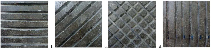
The concrete surface preparation method prior to attaching the synthetic wraps, as mandated by the FRP producer, was by grinding the surface to a depth of 4 mm, followed by sandblasting. This method resulted in shear de-bonding of the FRP to the concrete [1]. The wrap used in this research was a high strength black carbon fiber, embedded in a white thermoplastic heat-set fiber resin, attached to the concrete by a tri-methyl-hexane and epichloro-hydrin epoxy resin. Studies showed that the method of surface preparation, type of bonding agent and bond dimension strongly influences the bond between FRP and concrete [2, 3]. Based on this knowledge, four methods to enhance the both shear-bond and tensile-bond were introduced. The surface preparations were conducted by applying groves in the concrete surface on the designated 4 mm grinded surface. The groves had a depth and width of 2 mm and 0.5 mm respectively, and a distance of 10 mm apart. The groves’ configurations were perpendicular (code T); diagonal (code D); crossed (code C) and parallel (code L) to the line of tensile load (Fig. 1).
The aim of this study was to compare the individual shear- and tensile-bond failure behaviors of each surface treatment. The standardized treatment as mandated by the FRP producer was designated as type N, and functioned as controlling element. The application of groves was based on the main idea to enlarge the bonding agent’s contact area to the concrete, and to enhance the strain-flow distance by re-direct its path.
a. b. c. d.
Han Ay Lie/ Procedia Engineering 00 (2017) 000–000 3
3.Experimental research
3.1.Shear-bond behavior
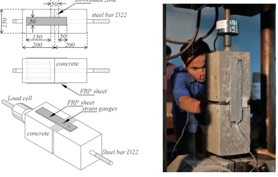
Shear-bond test methods for FRP are limited; research work on FRP in shear is mostly applied to FRP plates having a much higher rigidity as compared to sheets or wraps [4, 5, 6, 7, 8, 9]. Since the FRP sheets have significantly less stiffness as compared to FRP plates, the typical one-face-tensile, and the one-face and double-face-push tests as introduced by the majority of researchers, was not applicable. The effect of misalignment would heavily influence the outcome [10]. Considering all aspect, a modification of the test method based the fib-CEB technical specifications [2, 11] was chosen (Fig 2).
Fig. 2. Shear test set up and specimen preparation.
Instead of using steel clamps as was advised by the fib-CEB, a smaller bond area measuring only 50 by 50 mm was designed to localize bond failure. The opposite contact areas were made larger, measuring 50 by 150 mm. An un-bonded zone 50 mm in width was designated to prevent premature spalling due to high stress concentrations in the concrete corner. This un-bonded area was bridged by a two-ply FRP composite attached by an epoxy layer at the interface. The epoxy resin was also applied the exposed face of the FRP. The D22 steel bar dimension; its development length and the concrete reinforcements were carefully designed to ensure failure in the bond. Six specimens were prepared for each surface treatment, and standardized cylinders sized 150 by 300 mm were produced to monitor the 28th day’s concrete compression strength. The strength was recorded as 55.60 MPa.
3.2. concrete at the the concrete, a to the initial sti a 0.50 mm thic
en failing in sh rength was calc ar strength clos
te strength is 7 act same mate the FRP and c vation to the s at the bonded F
ction had a ma fness of 90 kN ally resulted in RP-resin specim
iffness of the m ckness of the e
Sri Tudjono/
ond and
concrete-SL failed due to d the concrete.
rea. This was d flow propagatio
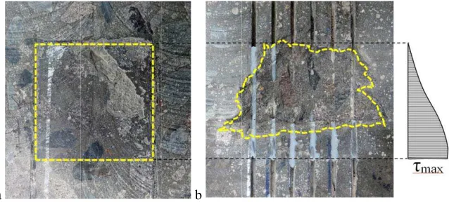
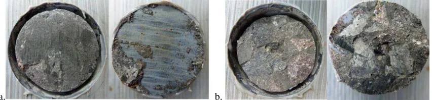
Fig. 4. Concrete
hear-bond had culated to be 5 sely approache
n a higher elast mens [12]. The material. The Y poxy resin laye
Procedia Enginee
b
shear failure; (a) D
o concrete shea Except for the due to the high on in the direct
spalling due to hig
a significantly 5.24 N/mm2, co es the concrete-The report on t n average shea quently the fai e in the un-bo uch higher stiff s of 63 kN/mm nation with a Y tic modulus as e double layere Young’s modul ers. The tensile
ering 00 (2017) 00
De-bonding failure
ar-cracking, wh predicted patte h stresses in th tion outward of
gh shear-stress con
y lower failure ompared to the e load was also
00–000
e; (b)Concrete-sh
hile the SN spe ern as seen in F e vicinity of th f the maximum
ncentrations.
stress as comp e concrete-shea y as predicted
shear test perf mined based on o assumed to b ar strength of 8 by the ACI co modulus of 55 G
3.3.D
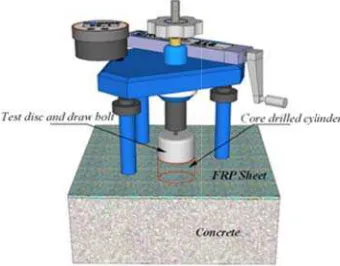
o test the resp een the FRP an an accuracy lev he concrete sur The synthetic s n testing, a cyl lab. The alumin
-bolt. This dra re, and the load
Tensile bond st
ll but one of t re due to tensio gth measured t
onse in direct nd concrete. T vel of less than rface was prep
heet was attach inder with a d num test disc w aw bolt had a ared in the sam hed to the con diameter of 50
was attached to conical head g 6).
Fig
ens failed in te e-bond failure r a. This value w del code 2010
was easily dis mode in the inte
/ Procedia Engine
n behavior of bond
xperimental m
. 6. Direct tensile t
ensile-bond mo resulted in a st was taken as av
predicted a ten tinguishable fr erface between
eering 00 (2017) 00
ded and un-bonded
-drilled in the h resin, and con
oncentric tensi
testing method.
ode. All other tress of 1.29 N verage of all th nsile strength o nnected to the ion force. The e and the morta
argets only the pull-out capaci
noted as TT, TD ed after seven d ace, creating a pull-off tester e specimen wa
ments resulted red to the conc oncrete tensile as tested till
Sri Tudjono/ Procedia Engineering 00 (2017) 000–000
a. b.
Fig. 7. (a) De-bonding in tension; (b) Mortar tension failure.
4.Analysis and discussion
The tensile behavior is less sensitive to surface preparation methods as compared to the behavior in shear. All test specimens expect one failed in the same mode, i.e. in the interface between aggregates and mortar. The tensile test data standard deviation was 0.72 as compared to 4.79 for the shear data, suggesting a much higher accuracy level for this experiment. The standardized equipment used for testing produced an almost perfect centric force, resulting in a uniform stress in the bond and concrete.
The fact that only one specimen in tension failed de-bonding mode suggested that the treatment by removing 4 mm of the surface, followed by sandblasting, is sufficient to maintain a perfect bond between the FRP sheet and the concrete. Any additional surface preparation is unnecessary, since all specimens failed in concrete tensile cracking. For members in bending, the tensile-bond contribution to the moment capacity is also negligible.
As for shear, the SN type specimen failed in de-bonding, underlined by the substantial lower failure stress reaching only 65% of the concrete shear-strength. All other surface treatments failed due to concrete-shear cracking. Whiles all tensile tests demonstrated a perfect circular failure section perpendicular to the applied load, the shear-bond tests showed a large variation in failure modes. Observed modes were: fracture in the un-shear-bonded and shear-bonded FRP sheets, partial de-bonding followed by concrete failure, and spalling. The failure surface areas were also non-uniform, suggesting that the testing method does not always produce a concentric load in the element. Errors observed during testing were: twisting of the steel bars at the starting of load application; flaws in the un-bonded FRP area due the manufacturing process; and non-uniformly distributed load to the both sides of the FRP. The method introduced by Irshidat and Al-Saleh [13] might overcome the unequal force distribution to the two test areas. This double shear test was directly applied to the bonded area through the FRP hooped around a cylindrical roller, resulting in more uniform force distribution in the both adjacent bond areas.
The shear-stress distribution, unlike tension, has a parabolic function and increases near the edge of the area. These high stresses resulted in spalling of concrete in the concrete edge, influencing the measured load magnitude at failure [14].
Contradictory to the tensile-bond, it was proven that a concrete surface grinding of 4 mm is insufficient to ensure that a perfect bonding in shear. This finding underlined the test results of Tudjono et al. in 2015 [1]. However, all four surface treatments resulted in the same failure mode, cracking of concrete in shear.
5.Conclusion
The introduced test methods to evaluate the tensile and shear-bond of FRP sheets were proven usable. The tensile test method was far more thorough when compared to the tensile testing method, based on comparison of the data’s standard deviation, and observing the variations in failure modes.
Han Ay Lie/ Procedia Engineering 00 (2017) 000–000 7
concrete-shear failure, it can be concluded that all methods are evenly effective. The choice on the surface preparation method is thus based on the consideration which application method yields in the easiest technique in combination with the least labor costs and execution time. These factors will influence the effectiveness of the method. The evaluation on the load distribution to the both testing faces showed that eccentric loading is of major concern; the method as introduced by the proposed fib-CEB code therefore requires the necessary evaluation and probable re-adjustments to minimize the load distribution imperfections during testing.
The stiffness response of the FRP when applied in multiple layers alters the stiffness behavior of the element. Care has to be taken when constructing a reinforcing system with multi FRP layers, since a brittle failure could be induced when a substantial number of FRP plies is used to increase the strength.
A next step is to investigate the depth, distance and width of the groves with respect to the concrete strength. A correlation between concrete strength and method could then be established and serve as guidance for applications in the field. A better bond performance will generally lead to an optimization in material usage; both the FRP and epoxy resins are chemical products which use should be controlled, if not minimized, to reduce the negative impact on the environment.
References
[1] S. Tudjono, A.L. Han, B.A. Hidayat, 2015, An Experimental Study to the Influence of Fiber Reinforced Polymer (FRP) Confinement on Beams Subjected to Bending and Shear, Procedia Engineering, 125 (2015) 1070-1075.
[2] H. Toutanji, G. Ortiz, The effect of surface preparation on the bond interface between FRP sheets and concrete members, Composite Structures, 53-4 (2001) 457–462.
[3] E.B. Dror, O. Rabinovitch, Size effect in the debonding failure of FRP strengthened beams, Engineering Fracture Mechanics, 156 (2016) 161-181.
[4] J.F. Chen, Z.J. Yang, G.DHolt, FRP or steel plate-to-concrete bonded joints: Effect of test methods on experimental bond strength, Steel and Composite Structures, 1-2 (2001) 231-244.
[5] J. Yao, J.G. Teng, J.F. Chen, Experimental study on FRP-to-concrete bonded joints, Composites: Part B, 36 (2005) 99-113.
[6] J.F. Chen, W.K. Pan, Three dimensional stress distribution in FRP-to-concrete bond test specimens, Construction and Building Materials, 20 (2006) 46-58.
[7] X.Z. Lu, J.G. Teng, L.P. Ye, J.J. Jiang, Bond-slip models for FRP sheets/plates bonded to concrete, Engineering Structures, 27 (2005), pp. 920-937.
[8] I. Akbar, D.J. Oehlers, M.S.M. Ali, Derivation of bond-slip characteristics for FRP plated steel members, Journal of Constructional Steel Research, 66 (2010) 1047-1056.
[9] F. Ceroni, M. Ianniciello, M. Pecce, 2016, Bond behavior of FRP carbon plates externally bonded over steel and concrete elements: experimental outcomes and numerical investigations, accepted in Composites, Part B (2016).
[10] P. Neto, J. Alfaiate, D. Dias-da-Costa, J. Vinagre, 2016, Mixed-mode fracture and load misalignment on the assessment of FRP-concrete bond connections, Composite Structures, 135 (2016), 49-60.
[11] I.A. Palmieri, S. Matthys, FRP RRT: Technical Specifications, fib-CEB publications (2008).
[12] P. Hamelin and E. Ferrier, Test report on reinforcement sytem SIKA CARBODUR et SIKA WRAP, Laboratoire Mécanique Matériaux et Structures (L2MS), France, pp. 1-12.
[13] R. Irshidat, M. H. Al-Saleh, Effect of using carbon nanotube modified epoxy on bond–slip behavior between concrete and FRP sheets. Construction and Building Materials, 105 (2016) 511-518.