Proceedings of International Conference on Mechanical &
Manufacturing Engineering (ICME2008)
General Mechanical Engineering
Manufacturing
Automotive Technology
Heat and Fluid Technology
Industrial Engineering
International Conference on Mechanical & Manufacturing Engineering (ICME2008), 21
–
23
May 2008, Johor Bahru, Malaysia.
© Faculty of Mechanical & Manufacturing Engineering, Universiti Tun Hussein Onn
Malaysia (UTHM), Malaysia.
ISBN: 97
–
98
–
2963
–
59
–
2
Faculty of Mechanical and Manufacturing Engineering
Universiti Tun Hussein Onn Malaysia (UTHM)
Proceedings of International Conference on Mechanical &
Manufacturing Engineering (ICME2008)
MANUFACTURING ENGINEERING
Study of Surface Roughness on Induction Hardened Steel using CBN Cutting Tool
MFG_ID_0001.pdf
Control of Blank Holder Force to Eliminate Wrinkling and Fracture in Deep-Drawing Rectangular Components
MFG_ID_0004.pdf
Implementation of Toyota Production System (TPS) in the Production Line of A Local Automotive Parts Manufacturer
MFG_ID_0006.pdf
Analysis of Variance on the Metal Injection molding parameters using a bimodal particle size distribution feedstock
MFG_ID_0009.pdf
Effect of Cryogenic Cooling during Grinding of Mild Steel and Stainless Steel
MFG_ID_0011.pdf
Traveling Salesman Problem with Precedence Constraint for Manufacturing Application: A Review
MFG_ID_0013.pdf
Strain Rate and Temperature Dependence of Mechanical Pproperties and Microstructure of Biomedical Titanium Alloy
MFG_ID_0020.pdf
Temperature Distribution and Bending Characteristics in Plastics Laser Forming
MFG_ID_0027.pdf
EFFECT OF ELECTRODE COOLING ON THE ELECTRICAL DISCHARGE MACHINING OF TITANIUM ALLOY
MFG_ID_0028.pdf
Optimal Lot Size of EPQ Model Considering Imperfect and Defective Products
MFG_ID_0052.pdf
Simulation based Control System for a Flat Screen Monitor Remanufacturing System
MFG_ID_0054.pdf
Scaling Effects In Milling Operations Of Tungsten-Copper-Composites
MFG_ID_0067.pdf
MFG_ID_0071.pdf
A Study on Dimensional Accuracy of FDM Machine Fabrication Style via DOE Technique
MFG_ID_0078.pdf
Design and Manufacturing of a Spherical Rolling Robot
MFG_ID_0083.pdf
The effect of nodularisation parameters on the quality of ductile iron
MFG_ID_0087.pdf
Development of an Artificial Neural Network Algorithm for Predicting the Cutting Force in End Milling of Inconel 718 Alloy
MFG_ID_0089.pdf
Mathematical Model of chip Serration frequency in end milling of Inconel 718
MFG_ID_0094.pdf
Potential Application of Rapid Prototyping Techniques to Fabricate a Laminated Rapid Tooling of Polyurethane Foam Mould
MFG_ID_0098.pdf
Influence of Micro End Milling Process Parameters on Surface Roughness
MFG_ID_0125.pdf
Fabrication of Micromold Cavity for Microreplication: A Review
MFG_ID_0127.pdf
Design of an aluminum alloy side door impact beam for passenger cars
MFG_ID_0143.pdf
The Effect of Radial Clearance between Impeller-Diffuser on Design Point Operation in a Centrifugal Fan
MFG_ID_0152.pdf
Automotive Part Prototype Development Using Reverse Engineering Technology
MFG_ID_0155.pdf
Integrating STEP with a PC-based Open Architecture Controller (OAPC-NC) for a Milling Process
MFG_ID_0169.pdf
Design of a Reliable Stair Climbing Tracked Robot
MFG_ID_0176.pdf
Processing and properties of PA6/MMT clay nanocomposites produced using selective laser sintering
MFG_ID_0193.pdf
Shear Deformation of Non-Crimp Fabrics
MFG_ID_0207.pdf
A Web-based Real-time Mould Machining Process Tracking System
MFG_ID_0222.pdf
A Study of Machining Error Compensation for Tool Deflection in Micro End-Milling
MFG_ID_0228.pdf
Development of a Micro Tool Inspection and Verification System
Cutting Force Simulation of Nose Radius Oblique Tools
MFG_ID_0233.pdf
Optimum hydroforming preform design by shape sensitivity analysis
MFG_ID_0239.pdf
An investigation of process parameters on quality of X-shape hydroformed joint by design of experiment and finite element method
MFG_ID_0240.pdf
Semi-automated Robotic Sculpting of Freeform Surfaces for Direct Digital Manufacture
MFG_ID_0316.pdf
The EWR of graphite and copper electrodes in electrical discharge machining (EDM) of AISI H13 harden steel
MFG_ID_0332.pdf
Experimental Study of the Effective Parameters in Polymeric Coating of Metal Powder Used as Raw Material in Powder-based Rapid Prototyping
MFG_ID_0333.pdf
A Study of Wire Looping Formation to Improve Ball Neck Strength of Wire Bonding Process
MFG_ID_0341.pdf
Modeling of General Etching System in Wafer Fabrication
MFG_ID_0343.pdf
A study of oxidized leadframe for QFN package on the cyclic test variable temperature effect
MFG_ID_0376.pdf
The Effect of Drill Point Geometry and Drilling Technique on Tool Life when Drilling Titanium Alloy, Ti-6Al-4V
MFG_ID_0393.pdf
Mathematical Modeling of Cutting Force in End Milling Ti-6Al4V using TiAlN Coated Carbide Tools
MFG_ID_0394.pdf
MECHANICAL
ENGINEERING
MANUFACTURING
ENGINEERING
AUTOMOTIVE
TECHNOLOGY
HEAT & FLUID
TECHNOLOGY
INDUSTRIAL
ENGINEERING
International Conference on Mechanical & Manufacturing Engineering (ICME2008), 21
–
23
May 2008, Johor Bahru, Malaysia.
© Faculty of Mechanical & Manufacturing Engineering, Universiti Tun Hussein Onn
Malaysia (UTHM), Malaysia.
Faculty of Mechanical and Manufacturing Engineering
Universiti Tun Hussein Onn Malaysia (UTHM)
Proceedings of International Conference on Mechanical & Manufacturing Engineering (ICME2008), 21– 23 May 2008, Johor Bahru, Malaysia. © Faculty of Mechanical & Manufacturing Engineering, Universiti Tun Hussein Onn Malaysia (UTHM), Malaysia.
ISBN: 97–98 –2963–59–2
Mathematical Modeling of Cutting Force in End Milling Ti-6Al4V
using TiAlN Coated Carbide Tools
Mohruni, A.S.1,2*, Sharif, S.2, Noordin, M.Y.2
1
Department of Mechanical Engineering Sriwijaya University
Indralaya - 30662 – South Sumatera Indonesia
2
Faculty of Mechanical Engineering Universiti Teknologi Malaysia
UTM Skudai - 81310 - Johor Malaysia
*[email protected], [email protected]
Abstract:
This paper deals with the development of cutting force predicted models in end milling titanium alloy Ti-6Al4V using TiAlN coated solid carbide tools under flood conditions. The primary machining parameters such as cutting speed, feed and radial rake angle, were used as independent variables for factorial design of experiment coupled with response surface methodology (RSM). Results from the 3D-response surface contour showed that the linear model generate better results than the second order models obtained during machining this advanced material. An optimum cutting conditions was also recognized for a particular range of cutting force values. The models were verified by analysis of variances and were found to be adequate.
Keywords: Cutting Force, End Milling, TiAlN Coated Carbide, Titanium Alloy, RSM.
1. Introduction
Numerous studies have shown titanium and its alloys are difficult to machine, regardless of the various types of cutting tools used. This has been attributed to their low thermal conductivity, which concentrates heat in the cutting zone (typically less than 25% that of steel), retention of strength at elevated temperatures and high chemical affinity for all cutting tool materials.
Although the cutting forces generated are not excessively high (almost similar to those with steel), they are confined to a small area due to the short chip contact length which leads to high stresses. The combination of high stress and temperature resulted in plastic deformation of the tool edge. Depth of cut
notching and chipping at the flank can also be a problem with intermittent cutting operations [1].
Knowledge of the cutting forces owing to a predictive model is very interesting with respect to the choice of machine tool power, the cutting tools and the optimization of cutting conditions for a given machining operation. It could allow the number of long and expensive tests to be limited and the best tool geometry to obtain quasi-constant and low cutting forces, which lead to a reduced tool wear and consequently, a better tool-life, to be found [2].
Proceedings of International Conference on Mechanical & Manufacturing Engineering (ICME2008), 21– 23 May 2008, Johor Bahru, Malaysia. © Faculty of Mechanical & Manufacturing Engineering, Universiti Tun Hussein Onn Malaysia (UTHM), Malaysia.
ISBN: 97–98 –2963–59–2
independent cutting conditions such as feed rate, cutting speed and depth of cut etc. This has reflected on the increased total cost of the study as it involved a large number of cutting experiments. Furthermore, with this purely experimental approach, researchers have investigated the effect of cutting parameters on cutting forces using machining experiments based on a one-factor-at a-time design, without having any idea about the behavior of cutting forces when two or more cutting factors are varied at the same time. Furthermore, this approach cannot describe and identify, with a great accuracy, the effect of the interactions of different independent variables on the responses when they are varied simultaneously [3].
Recent study takes into account the effect of simultaneous variations of three cutting parameters such as cutting speed (V), feed per tooth (fz)and radial rake angle ( o) on
the behavior of cutting forces by utilizing response surface methodology (RSM). RSM is a group of mathematical and statistical techniques that are useful for modeling the relationship between the input parameters (cutting conditions) and the output variable or response (cutting force) [4].
This method was also used by previous researchers [5]-[9], which studied cutting force as the machining response.
2. Mathematical Models for Cutting Force
In this study, RSM was used and the mathematical models relating to the machining responses were developed according to Alauddin et. al.[5].
2.1 Postulation of the Mathematical Models
Assuming that the proposed model for cutting force is merely depend on cutting speed V, feed per tooth fz and radial rake o.
Other factors, which influence machining process, are kept constant. Thus, the cutting
By utilizing a natural logarithmic transformation Equation (1) can be written in first order polynomial as
ε
which can be transformed to
ε
and finally can be formed as
3
natural logarithmic value of predictive (estimated) tangential force or cutting force, x0
= 1 as a dummy variable, xi (i= 1 to 3) are the
coded variables of V, fzand o respectively, =
ln ’ and bj (j = 0 to 3) are the model
parameters to be estimated using experimental data [5].
If the observation region is extended, then the second order model is useful to represent the effect of second order and interaction components. The second order can be extended from the first order model in estimated using least squares method and 2 is
the predicted response on natural logarithmic scale.
Proceedings of International Conference on Mechanical & Manufacturing Engineering (ICME2008), 21– 23 May 2008, Johor Bahru, Malaysia. © Faculty of Mechanical & Manufacturing Engineering, Universiti Tun Hussein Onn Malaysia (UTHM), Malaysia.
ISBN: 97–98 –2963–59–2
2.2 Experimental Design.
In order to determine the Equation of the response surface, several experimental designs have been developed which attempt to approximate the Equation using the smallest number of possible experiments [4][10].
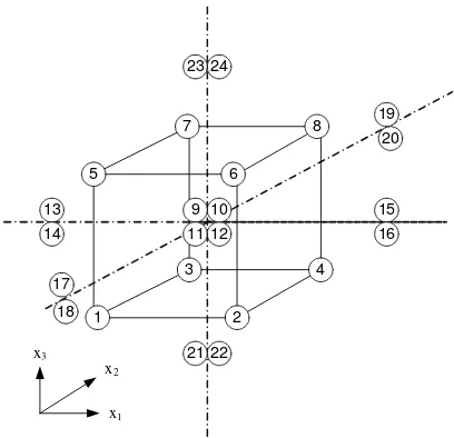
In this study the 2k-factorial design using the first 8 points from design of experiments as shown in Figure 1, was carried out for screening test. This design is necessary when interactions between variables are to be investigated. Furthermore, factorial design allow the effects of a factor to be estimated at several levels of other factors, giving conclusions that are valid over a range of experimental conditions [4][10].
1
Figure 1: Design of Experiment.
To investigate the effect of nonlinearity in the observation region and to construct an estimated errors with nc -1 (nc is
number of center points), it is useful to add center points in screening test with 2k-factorial design when the factorial points in the design are not replicated [10]. Four experiments represent added center points to the first 8 points and were repeated four times to estimate the pure error.
An extended design of 23-factorial design is a second order central composite design (CCD), which easily gained by augmentation of 23-factorial design with
replicated star points ( = 1.4142 [9]) as shown completely in Figure 1.
2.3 Coding of the Independent Variables
The independent variables were coded by taking into account the capacity and limiting cutting conditions of milling machine. The following transforming Equation was used.
natural value to the base or zero level [5][9]. The coded values of the independent variables shown in Table 1 for use in Equation (4) and (5) were obtained from the following corresponding to its natural value of o.
Table 1: Levels of Independent Variables for Ti-6Al4V
Proceedings of International Conference on Mechanical & Manufacturing Engineering (ICME2008), 21– 23 May 2008, Johor Bahru, Malaysia. © Faculty of Mechanical & Manufacturing Engineering, Universiti Tun Hussein Onn Malaysia (UTHM), Malaysia.
ISBN: 97–98 –2963–59–2
3. Experimental Set-Up
A CNC MAHO 700S machining centre was used for experimentation, while side-milling process was conducted with a constant axial depth of cut aa 5 mm and radial
depth of cut ae 2 mm under flood coolant with
a 6 % concentration.
The reference workpiece material of Ti-6Al4V, which was a rectangular block of 110 mm x 55 mm x 150 mm, was used for cutting force measurements.
The end mill was clamped to the tool holder with a constant 22 mm overhang. The TiAlN coated grade-K-30 solid carbide end mills with different radial rake angle according to design of experiment, were used in the experiments. To avoid the influence of tool wear, the forces data (Fx, Fy, Fz) were
recorded during the initial cut when the end mill was still new without wear. The recording of cutting force was carried out using multi component force measuring system consisting of the following elements:
• A 3-component dynamometer comprising of basic unit (Kistler, Type 9265B) and a screwed-on working adapter for milling (Kistler, Type 9443B).
• A multi channel charge amplifier (Kistler, Type 5019A).
• A data acquisition system consisting of a personal computer (PC) equipped with an A/D board as well as the DynoWare software (Kistler, Type 2825 D1-2, version 2.31).
The analysis for the developed models was carried out using a Design Expert 6.0 package.
4. Experimental Results and Discussion
4.1 Development of the Cutting Force Model using 2k-Factorial Design.
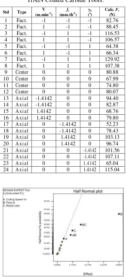
The development of the cutting force model was based on the first 12 trials of the experiments shown in Table 2. From the main effect plot in Figure 2, it was observed that the most significant factor that affected the cutting
force was factor B (feed), followed by interaction BC (feed and radial rake angle), C (radial rake angle), interaction AB (cutting speed and feed) and lastly factor A (cutting speed.
Table 2: Cutting Force Fta or Fc when using
TiAlN Coated Carbide Tools.
Std Type V
Proceedings of International Conference on Mechanical & Manufacturing Engineering (ICME2008), 21– 23 May 2008, Johor Bahru, Malaysia. © Faculty of Mechanical & Manufacturing Engineering, Universiti Tun Hussein Onn Malaysia (UTHM), Malaysia.
ISBN: 97–98 –2963–59–2
The cutting force prediction model can be formulated as
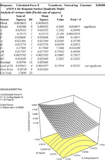
3 force decreases with increasing cutting speed and radial rake angle. In contrary, it increases with increase in feed. From interaction terms, it was observed that the combination of speed and feed contributes to decrease in cutting force. However, the combination of feed and radial rake angle adversely increases the cutting force, whilst the feed alone tends to increase the cutting force. From the ANOVA results in Table 3, it is evident that the 3F1-model is valid for the observation region, because the lack of fit (LOF) is not significant.
Table 3: ANOVA for 3F1-Cutting Force Prediction Model using TiAlN Coated Tools
Figure 3: Response Surface of V and fz for
3F1-Cutting Force Model using TiAlN Coated Tools.
Figure 4: Response Surface of fzand o for
3F1-Cutting Force Model using TiAlN Coated Tools.
Figure 5: Response Surface of V and o for
3F1-Cutting Force Model using TiAlN Coated Tools.
Proceedings of International Conference on Mechanical & Manufacturing Engineering (ICME2008), 21– 23 May 2008, Johor Bahru, Malaysia. © Faculty of Mechanical & Manufacturing Engineering, Universiti Tun Hussein Onn Malaysia (UTHM), Malaysia.
ISBN: 97–98 –2963–59–2
from the highest slope of the feed curve. The last response surface for investigation of performance evaluation is shown in Figure 5. It indicates that radial rake angle has more significant effect than cutting speed on cutting force. The maximum cutting force was achieved with combination of the lowest radial rake angle and lowest cutting speed when end milling Ti-6Al4V using TiAlN coated tools.
In combination of all independent variables, the minimum cutting force can be achieved when using the lowest feed coupled with the highest cutting speed and highest radial rake angle.
4.2 Development of the First Order Cutting Force Model using CCD.
The same data from Table 2 for 3F1-model were used in developing the first order CCD model. According to fit and summary test for the first order cutting force model (Table 4), a linear model was suggested.
Table 4: Fit and Summary Test for the First Order Cutting Force CCD Model using TiAlN
Coated Tools
The first order CCD model for cutting force is
3 2
1 0.21403 0.0528
02293 . 0 4615 . 4
ˆ x x x
y= − + − (10)
which can be presented in the following form
17062 . 0 50521 . 0 22086 . 0
32819 .
1811 − −
= z o
c V f
F γ (11)
where Fc is the predicted cutting force in (N).
To validate the first order CCD cutting force model, ANOVA was conducted and the results are presented in Table 5. It is obvious
that the LOF of the cutting force linear CCD model was not significant. Thus the model is valid for end milling of Ti-6Al4V using TiAlN coated carbide tools under wet conditions with the following range of respective cutting speed V, feed per tooth fz
and radial rake angle o: 130 V 160 m.min
-1
; 0.03 fz 0.07 mm.tooth-1; 7 o 13 (o).
Table 5: ANOVA for 1st order CCD-Cutting Force Model using TiAlN Coated Tools
Figure 6: Response Surface of V and fz for 1 st
CCD-Cutting Force Model using TiAlN Coated Tools.
Figure 7: Response Surface of V and o for 1st
Proceedings of International Conference on Mechanical & Manufacturing Engineering (ICME2008), 21– 23 May 2008, Johor Bahru, Malaysia. © Faculty of Mechanical & Manufacturing Engineering, Universiti Tun Hussein Onn Malaysia (UTHM), Malaysia.
ISBN: 97–98 –2963–59–2
Figure 8: Response Surface of fz and o for 1st
CCD-Cutting Force Model using TiAlN Coated Tools.
More information resulted in the CCD linear cutting force model is shown by the response surface in Figure 6 to 8. From these graphical plots, it can be recognized that increasing the cutting speed decreases the cutting force slightly. Similar findings was reported by other researchers [11][12] for the observation region of cutting speed.
4.3 Development of the Second Order Cutting Force Model using CCD.
A second order model was postulated to extend the variables range in obtaining the relationship between the cutting force and machining variables. The model is based on the second order CCD model for k = 3 (Figure 1) and 24 set of experimental results as given in Table 2. The results is presented in the
From ANOVA results, it was also found that the second order CCD model can be used as the mathematical model in the region of observation, since the LOF is not significant as shown in Table 6.
It was interesting to observe that when the region was extended, the contour of cutting force in the cutting range changes from linear (Figure 6) to a slightly curve form (Figure 9). This was also confirmed by other
researchers [11][12] for low and high cutting speeds region.
Table 6: ANOVA for 2nd order CCD-Cutting Force Model using TiAlN Coated Tools
Figure 9: Response Surface of V and fz for 2nd
CCD-Cutting Force Model using TiAlN Coated Tools.
Figure 10: Response Surface of V and o for
Proceedings of International Conference on Mechanical & Manufacturing Engineering (ICME2008), 21– 23 May 2008, Johor Bahru, Malaysia. © Faculty of Mechanical & Manufacturing Engineering, Universiti Tun Hussein Onn Malaysia (UTHM), Malaysia.
ISBN: 97–98 –2963–59–2
Figure 11: Response Surface of fz and o for
2nd CCD-Cutting Force Model using TiAlN Coated Tools.
They found that the cutting force was very high at low cutting speed and reduced rapidly at medium cutting speed and finally increased slightly with further increase in cutting speed. It was also observed in Figure 9 that there was a significant increase in cutting force with increase in feed.
The significant findings from the experimental result in Figure 10 as compared to Figure 7 is that the effect of radial rake angle in the extended observation region (using second order model) increased significantly than in the linear region due to the value of the radial rake angle almost achieved the maximum value. Nevertheless, increasing trend when radial rake angle increased can still be seen.
It is obvious in Figure 11 that the effect of feed as a function of radial rake angle decreases with increasing radial rake angle. The maximum value was achieved when the highest feed combined with the highest radial rake angle.
Further observation by means of ANOVA, was conducted to find the significant level of each factor of the model and to reduce the second order CCD model into a simpler form. This method known as backward elimination, can be used when some of the influencing factors have “Probe>F” larger than 0.05 confident level. Contribution of each factor can also be found from the value of coefficient of each factor (Equation (12)). The larger the coefficient of each factor,
the higher the contribution of each factor to the response (cutting force).
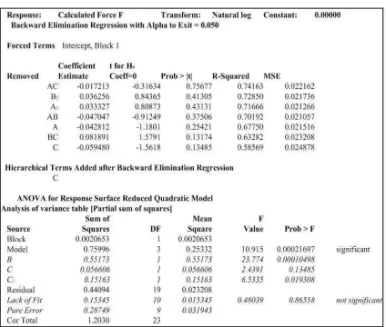
ANOVA was conducted once again using the backward elimination to find the reduced form of Equation (12). The results are presented in Table 7.
Table 7: ANOVA for 2nd order CCD-Cutting Force Model using TiAlN Coated Tools.
Comparing the ANOVA in reduced form (Table 7) with ANOVA in completed form (Table 6), the mean square error (MSE) of ANOVA in reduced form is higher than MSE of ANOVA in completed form.
The Equation in reduced form can be presented as
2 3 3
2 0.05948 0.10664
1857 . 0 3182 . 4
ˆ x x x
y= + − + (13)
Equation (13) is much simpler than the origin of Equation (12). However, the accuracy decreased with reduced parameters involved in the original Equation (12).
4.4 Optimum Cutting Conditions
Proceedings of International Conference on Mechanical & Manufacturing Engineering (ICME2008), 21– 23 May 2008, Johor Bahru, Malaysia. © Faculty of Mechanical & Manufacturing Engineering, Universiti Tun Hussein Onn Malaysia (UTHM), Malaysia.
ISBN: 97–98 –2963–59–2
Table 8: Numerical Optimization of validated cutting force model for Fc minimum
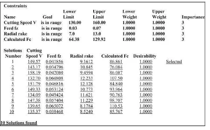
Table 9: Numerical Optimization of validated cutting force model for Fc in range
5. Conclusions
• Response surface methodology (RSM) has proved to be a successful technique that can be used to predict the cutting force Fc
and to reveal the relationship between independent cutting conditions and cutting force with minimum set of trials.
• There are three appropriate prediction models namely 3F1, 1st and 2nd order CCD model to formulate the relationship amongst machining parameters such as cutting speed, feed and radial rake angle. • The models indicate that feed is the most
significant factor, which influenced cutting force. It increases significantly with increasing feed in the observation region. • The first optimum cutting condition to
achieve minimum cutting force is cutting speed V = 133.20 m.min-1, feed fz = 0.03
mm.tooth-1 and radial rake angle o =
12.98 (o).
• The second optimum cutting condition when cutting force is in range, is cutting speed V = 149.57 m.min-1, feed fz = 0.042
and radial rake angle o = 9.2 (o).
Acknowledgements
The authors wish to thank the Research Management Center, UTM and the Ministry of Science, Technology and Innovation Malaysia for their financial support to the above project through the IRPA funding 03-02-02-0068 PR0074/03-01- Vote no. 74545.
References
[1]. H. Niemann, Ng. Eu-gene, H. Loftus, A. Sharman, R. Dewes and D. Aspinwall,
Metal Cutting and High Speed
Machining, edited by D. Dudzinski, A. Molinari, H. Schulz, Kluwer Academic/Plenum Publisher.
[2]. S. Bissey-Breton, G. Poulachon and F. Lopujoulade, Proceeding of the Institution of Mechanical Engineers,
Part B: Journal of Engineering
Manufacture, 220, pp. 579-587, January, 2006.
[3]. K.A. Abou-El-Hossein, K. Kadirgama, M. Hamdi and K.Y. Benyounis, Journal of Materials Processing Technology,
182, pp. 241-247, July, 2007.
[4]. D.C. Montgomery, Design, Analysis of Experiments, 5th ed. John Wiley & Sons, 2001.
[5]. M. Alauddin, M.A. El-Baradie and M.S.J. Hashmi, Journal of Materials Processing Technology, 58, pp. 100-108, 1996.
[6]. H.F. Kuang and Y.C. Hung, Journal of Materials Processing Technology, 72, pp. 42-27, 1997.
[7]. M.Y. Noordin, V.C. Venkatesh, S. Sharif, S. Elting and A. Abdullah,
Journal of Materials Processing
Technology, 145, pp. 46-58, 2004. [8]. T. Radhakrishnan and U. Nandan,
Proceedings of International Conference on Mechanical & Manufacturing Engineering (ICME2008), 21– 23 May 2008, Johor Bahru, Malaysia. © Faculty of Mechanical & Manufacturing Engineering, Universiti Tun Hussein Onn Malaysia (UTHM), Malaysia.
ISBN: 97–98 –2963–59–2
[9]. A.S. Mohruni, S. Sharif and M.Y. Noordin, Proceeding of Regional
Postgraduate Conference on
Engineering and Science, Johore Bahru, Malaysia, July 2006, pp. 337-342. [10]. R.H. Meyers and D.C. Montgomery,
Response Surface Methodology: Process
and Product Optimization using
Designed Experiments, 2nd ed. John Wiley & Sons Inc., 2002.
[11]. E.M. Trent and P.K. Wright, Metal
Cutting, 4th ed. Butterworth and
Heinemann, 2000.
[12]. J.H. Xu, K.Q. Ren and G.S. Geng, In